CN213334597U - Energy gathering component for gas stove and gas stove - Google Patents
Energy gathering component for gas stove and gas stove Download PDFInfo
- Publication number
- CN213334597U CN213334597U CN202020689430.XU CN202020689430U CN213334597U CN 213334597 U CN213334597 U CN 213334597U CN 202020689430 U CN202020689430 U CN 202020689430U CN 213334597 U CN213334597 U CN 213334597U
- Authority
- CN
- China
- Prior art keywords
- annular
- energy gathering
- ring
- energy
- gas stove
- Prior art date
- Legal status (The legal status is an assumption and is not a legal conclusion. Google has not performed a legal analysis and makes no representation as to the accuracy of the status listed.)
- Active
Links
Images


Landscapes
- Cookers (AREA)
Abstract
本实用新型公开了一种燃气灶用聚能组件及燃气灶,所述聚能组件包括:第一聚能圈;第二聚能圈,设置在所述第一聚能圈内并与所述第一聚能圈配合形成密封的保温隔热腔。通过本实用新型解决了现有技术燃气灶存在的热量散失多,热能有效利用率低的问题。

The utility model discloses an energy gathering component for a gas stove and a gas stove. The energy gathering component comprises: a first energy gathering circle; and a second energy gathering circle, which is arranged in the first energy gathering circle and is connected with the The first energy gathering ring cooperates to form a sealed thermal insulation cavity. The utility model solves the problems of large heat loss and low effective utilization rate of heat energy existing in the prior art gas stove.
Description
Technical Field
The utility model belongs to the household electrical equipment field, concretely relates to gas-cooker gathers can subassembly and has this improvement of gathering the gas-cooker structure of subassembly.
Background
Present gas-cooker, the primary structure is including the top of a kitchen range, furnace end and pot frame of setting on the top of a kitchen range, still be provided with flourishing liquid dish on the top of a kitchen range, place the pot frame on flourishing liquid dish, when using, the flare-outing that sends through the gas in the top of a kitchen range heats food in the pot, because the pot frame is hollow out construction, when using, can lead to the heat that produces through the gas to be given off by a large amount of outside, the loss of flow falls, not only heat loss is big but also leads to the effective utilization rate low-down of heat energy, user use cost uprises.
SUMMERY OF THE UTILITY MODEL
The utility model discloses heat to prior art gas-cooker existence scatters and disappears much, and the problem that heat energy effective utilization is low provides a new gas-cooker with gathering the subassembly, and it is thermal-insulated effectual and can reduce the heat and scatter and disappear, improve heat energy effective utilization.
In order to realize the purpose of the utility model, the utility model adopts the following technical scheme to realize:
a concentrator assembly for a gas cooker, the concentrator assembly comprising:
a first energy gathering ring;
and the second energy gathering ring is arranged in the first energy gathering ring and is matched with the first energy gathering ring to form a sealed heat-insulating cavity.
Furthermore, the second energy gathering ring is circumferentially provided with an annular flange, an annular platform is formed on the inner side wall of the first energy gathering ring, the second energy gathering ring is clamped on the annular platform of the first energy gathering ring through the annular flange, and the bottom surface of the annular flange corresponds to and is attached to the top surface of the annular platform.
Further, the bottom edge of the second energy gathering ring fits against the bottom edge of the first energy gathering ring.
Further, the first energy gathering ring further comprises:
the annular base is formed on the inner side wall of the annular base, and the top surface of the annular table is lower than that of the annular base;
the outer side surface of the third ring-shaped element is an arc-shaped curved surface which is smoothly transited from the direction close to the annular table to the direction away from the annular table, and the corresponding caliber size of the third ring-shaped element is gradually reduced from the direction close to the annular table to the direction away from the annular table.
Further, the second energy ring comprises:
a first annular member;
and the outer side surface of the second annular part is an arc-shaped curved surface which smoothly transitions from the direction close to the first annular part to the direction far away from the first annular part, and the corresponding caliber size of the second annular part gradually decreases from the direction close to the first annular part to the direction far away from the first annular part.
Further, be provided with the card of mutually supporting between first energy gathering circle and the second energy gathering circle and establish the structure, the card is established the structure and is established including establishing the card protruding/draw-in groove at second annular member bottom edge with establish the draw-in groove/card protruding at third annular member bottom edge.
Furthermore, the heat-insulating cavity is filled with heat-insulating materials.
A gas stove comprises a cooking range head, a pot frame and an energy gathering assembly, wherein the energy gathering assembly is arranged on the periphery of the cooking range head in a heat exchange mode, and the pot frame is arranged on the second energy gathering ring.
Further, the outer profile of the wok stand is matched with the inner profile of the first annular piece and is larger than the maximum profile diameter of the second annular piece.
Further, the energy-collecting device comprises a cooking bench and a liquid-containing disc, wherein the liquid-containing disc is arranged on the cooking bench, and the first energy-collecting ring is arranged on the liquid-containing disc.
Compared with the prior art, the utility model discloses an advantage is with positive effect:
the utility model discloses in the energy of proposing subassembly, can enclose the cooperation through first energy of gathering and form the thermal-insulated chamber of sealed heat preservation with the second energy of gathering, place the week circle at the kitchen range when using, can keep warm and keep apart heat and transmit to the outside through the sealed thermal-insulated chamber that sets up when the natural gas burns, reduced calorific loss for the heat can be kept apart and gathering the inside by the complete utilization of subassembly, improved the thermal efficiency.
Other features and advantages of the present invention will become more apparent from the following detailed description of the invention when read in conjunction with the accompanying drawings.
Drawings
In order to more clearly illustrate the technical solutions in the embodiments of the present invention, the drawings needed to be used in the embodiments will be briefly described below, and it is obvious that the drawings in the following description are some embodiments of the present invention, and it is obvious for those skilled in the art to obtain other drawings without creative efforts.
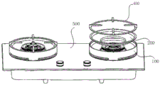
Fig. 1 is a schematic structural view of an embodiment of the energy concentrating assembly for a gas cooker according to the present invention;
fig. 2 is a schematic structural view of a pot holder and a power collecting assembly in an embodiment of the power collecting assembly for a gas cooker of the present invention;
fig. 3 is an exploded view of the first energy concentrating ring and the second energy concentrating ring according to an embodiment of the energy concentrating assembly for a gas cooker of the present invention;
fig. 4 is an exploded view of the first energy collecting ring, the second energy collecting ring and the pot holder according to an embodiment of the energy collecting assembly for a gas cooker.
Detailed Description
In order to make the objects, technical solutions and advantages of the present invention more apparent, the present invention will be described in further detail with reference to the accompanying drawings and embodiments.
It should be noted that in the description of the present invention, the terms of direction or positional relationship indicated by the terms "upper", "lower", "left", "right", "vertical", "horizontal", "inner", "outer", etc. are based on the directions or positional relationships shown in the drawings, which are merely for convenience of description, and do not indicate or imply that the device or element must have a specific orientation, be constructed and operated in a specific orientation, and thus, should not be construed as limiting the present invention. Furthermore, the terms "first" and "second" are used for descriptive purposes only and are not to be construed as indicating or implying relative importance.
The first embodiment is as follows:
the utility model provides a gas-cooker is with embodiment of gathering energy subassembly, it is shown with reference to fig. 2-4, it is specific, in this embodiment gather the energy subassembly and include:
a first energy concentrating ring 100;
the second energy gathering ring 200 is arranged in the first energy gathering ring 100 and is matched with the first energy gathering ring 100 to form a sealed heat-insulating cavity, the heat-insulating cavity is a hollow cavity, when the energy gathering device is used, the energy gathering assembly is placed on the periphery of a cooking range 300 of a gas stove, when the cooking range 300 works, natural gas is combusted, hot gas emitted by the natural gas is combusted, and after the hot gas rises to the bottom of a pot, the hot gas cannot be emitted through the blocking of the first energy gathering ring 100 and the second energy gathering ring 200, and can be fully combusted in the inner part after being blocked by the first energy gathering ring 100 and the second energy gathering ring 200;
when the gas is burnt, the second energy gathering ring 200 positioned inside is contacted with the gas, the heat emitted by the burning of the natural gas can be firstly transmitted to the second energy gathering ring 200, and as the heat insulation cavity is formed between the second energy gathering ring 200 and the first energy gathering ring, when the heat is continuously transmitted outwards, the heat and the external air can be isolated through the action of the heat insulation cavity, so that the heat insulation effect is realized;
meanwhile, the hollow cavity is hollow, so that heat transfer can be blocked by air in the hollow cavity, the condition of heat leakage is avoided, further, heat loss is reduced, the heat efficiency is improved, and meanwhile, the use cost of a user is also reduced.
In order to realize the sealing connection between the first energy gathering ring 100 and the second energy gathering ring 200, in the embodiment, an annular flange 210 is arranged around the second energy gathering ring 200, an annular table 110 is formed on the inner side wall of the first energy gathering ring 100, the second energy gathering ring 200 is arranged inside the first energy gathering ring 100 and clamped on the annular table 110 of the first energy gathering ring 100 through the annular flange 210, and the bottom surface of the annular flange 210 is correspondingly and closely attached to the top surface of the annular table 110, so that the sealing connection at the top of the first energy gathering ring 100 and the second energy gathering ring 200 is ensured.
To achieve a sealed connection at the bottom of the first and second shaped rings 100, 200, the bottom edge of the second shaped ring 200 fits against the bottom edge of the first shaped ring 100.
Preferably, the first energy gathering ring 100 further comprises: the annular base 120 and the third ring member 130, the annular table 110 is formed on the inner side wall of the annular base 120, the top surface of the annular table 110 is lower than the top surface of the annular base 120, the third ring member 130 is connected with the annular table 110, the outer side surface of the third ring member 130 is an arc-shaped curved surface which is smoothly transited from the direction close to the annular table 110 to the direction away from the annular table 110, and the corresponding caliber size of the third ring member gradually decreases from the direction close to the annular table 110 to the direction away from the annular table 110.
A preferred embodiment of the second energy concentrating ring 200 in the present embodiment is: the second energy ring 200 comprises: a first ring member 220 and a second ring member 230 connected to the first ring member 220.
The outer side surface of the second ring member 230 is an arc-shaped curved surface which smoothly transitions from the direction close to the first ring member 220 to the direction far from the first ring member 220, and the corresponding caliber size of the second ring member gradually decreases from the top to the bottom.
In order to ensure the firm connection between the first energy gathering ring 100 and the second energy gathering ring 200, a clamping structure capable of being matched with each other is further arranged between the first energy gathering ring 100 and the second energy gathering ring 200, the clamping structure includes a clamping protrusion/clamping groove (not shown in the figure) arranged at the bottom edge of the second ring member 230 and a clamping groove/clamping protrusion (not shown in the figure) arranged at the bottom edge of the third ring member 130, the clamping protrusion may be arranged at the bottom edge of the first energy gathering ring 100, the clamping groove may be correspondingly arranged at the bottom edge of the second energy gathering ring 200, and of course, the clamping protrusion and the clamping groove may be reversely arranged on the first energy gathering ring 100 and the second energy gathering ring 200, which is not limited herein. When the fixing device is fixed, the clamping protrusions can be correspondingly clamped into the clamping grooves to realize clamping and fixing.
In order to further enhance the heat preservation and insulation effect of the gas stove in this embodiment, the heat preservation and insulation cavity is further filled with a heat preservation and insulation material, and the heat preservation and insulation material may be a heat preservation member such as heat preservation cotton, polyurethane heat preservation foam, and the like, and is not limited specifically here.
Example two:
the embodiment of the gas stove is further provided, and referring to fig. 1, the gas stove includes a burner 300 and a wok stand 400, and further includes the energy collecting assembly described in the first embodiment, the energy collecting assembly is arranged around the burner 300 for heat exchange, and the wok stand 400 is arranged on the second energy collecting ring 200. Specifically, the outer profile of the wok stand 400 is matched with the inner profile of the first ring member 220 and is larger than the maximum profile diameter of the second ring member 230. This ensures that the wok stand 400 can be just placed in the first ring member 220 and simultaneously be restrained by the second ring member 230, preventing it from falling downward.
The gas stove in the embodiment further comprises a cooking bench 500 and a liquid containing disc 600, wherein the liquid containing disc 600 is arranged on the cooking bench 500, and the first energy collecting ring 100 is arranged above the liquid containing disc 600.
The above embodiments are only used to illustrate the technical solution of the present invention, and not to limit it; although the present invention has been described in detail with reference to the foregoing embodiments, it will be apparent to those skilled in the art that modifications may be made to the embodiments described in the foregoing embodiments, or that equivalents may be substituted for elements thereof; such modifications and substitutions do not depart from the spirit and scope of the present invention, which is claimed.
Claims (8)
Priority Applications (1)
| Application Number | Priority Date | Filing Date | Title |
|---|---|---|---|
| CN202020689430.XU CN213334597U (en) | 2020-04-29 | 2020-04-29 | Energy gathering component for gas stove and gas stove |
Applications Claiming Priority (1)
| Application Number | Priority Date | Filing Date | Title |
|---|---|---|---|
| CN202020689430.XU CN213334597U (en) | 2020-04-29 | 2020-04-29 | Energy gathering component for gas stove and gas stove |
Publications (1)
| Publication Number | Publication Date |
|---|---|
| CN213334597U true CN213334597U (en) | 2021-06-01 |
Family
ID=76058361
Family Applications (1)
| Application Number | Title | Priority Date | Filing Date |
|---|---|---|---|
| CN202020689430.XU Active CN213334597U (en) | 2020-04-29 | 2020-04-29 | Energy gathering component for gas stove and gas stove |
Country Status (1)
| Country | Link |
|---|---|
| CN (1) | CN213334597U (en) |
Cited By (1)
| Publication number | Priority date | Publication date | Assignee | Title |
|---|---|---|---|---|
| CN115789710A (en) * | 2022-12-29 | 2023-03-14 | 海信(山东)厨卫有限公司 | Gas stove |
-
2020
- 2020-04-29 CN CN202020689430.XU patent/CN213334597U/en active Active
Cited By (1)
| Publication number | Priority date | Publication date | Assignee | Title |
|---|---|---|---|---|
| CN115789710A (en) * | 2022-12-29 | 2023-03-14 | 海信(山东)厨卫有限公司 | Gas stove |
Similar Documents
| Publication | Publication Date | Title |
|---|---|---|
| CN112923409B (en) | Energy gathering ring and gas stove | |
| CN115388429A (en) | Energy-collecting pan rack and gas cooker | |
| CN210153883U (en) | Energy-gathering pot holder assembly and gas stove | |
| CN217843998U (en) | Energy-gathering plate with pot holder and gas stove | |
| CN218954960U (en) | Energy-collecting pan pot rack and kitchen range | |
| CN110345524B (en) | Pot rack and gas stove | |
| CN110553298B (en) | Heat insulation cover for stove and stove using the heat insulation cover | |
| CN221324538U (en) | Energy gathering ring for gas stove and gas stove | |
| CN219222531U (en) | Pot support and gas cooking utensils | |
| CN210979960U (en) | Energy-gathering pot holder and gas stove using same | |
| CN112013433B (en) | Energy-gathering ring pot rack assembly and gas stove | |
| CN218269201U (en) | Energy gathering structure and stove | |
| CN214501351U (en) | Energy gathering ring and gas stove | |
| CN114659142B (en) | Energy-collecting pan pot rack and gas cooker | |
| CN212378012U (en) | Integrated kitchen and gas-cooker of liquid dish and company's dish are held in area | |
| CN113587093B (en) | Energy gathering ring assembly and gas stove | |
| CN212841713U (en) | Integrated kitchen and gas-cooker of liquid dish attached circle are held in area | |
| CN111998419B (en) | Energy gathering assembly and gas stove | |
| CN217604176U (en) | Pot rack and gas stove | |
| CN222578308U (en) | Energy-gathering pan pot rack and gas stove | |
| CN222417593U (en) | Suspension type energy collection disc structure | |
| CN223228464U (en) | Double-layer energy-gathering pot rack and gas stove | |
| CN219995393U (en) | Energy-collecting pot holder | |
| CN222578311U (en) | Pot holder and stove | |
| CN217785246U (en) | Pot rack and gas stove |
Legal Events
| Date | Code | Title | Description |
|---|---|---|---|
| GR01 | Patent grant | ||
| GR01 | Patent grant |