CN213333998U - Annular lamp convenient for light source installation - Google Patents
Annular lamp convenient for light source installation Download PDFInfo
- Publication number
- CN213333998U CN213333998U CN202021706368.7U CN202021706368U CN213333998U CN 213333998 U CN213333998 U CN 213333998U CN 202021706368 U CN202021706368 U CN 202021706368U CN 213333998 U CN213333998 U CN 213333998U
- Authority
- CN
- China
- Prior art keywords
- annular
- light source
- mounting groove
- lamp
- convenient
- Prior art date
- Legal status (The legal status is an assumption and is not a legal conclusion. Google has not performed a legal analysis and makes no representation as to the accuracy of the status listed.)
- Expired - Fee Related
Links
- 238000009434 installation Methods 0.000 title claims abstract description 42
- 241001465382 Physalis alkekengi Species 0.000 claims abstract description 22
- 239000004020 conductor Substances 0.000 claims abstract description 20
- 230000005611 electricity Effects 0.000 claims abstract description 10
- 241000758789 Juglans Species 0.000 claims description 7
- 235000009496 Juglans regia Nutrition 0.000 claims description 7
- 235000009137 Quercus alba Nutrition 0.000 claims description 7
- 241001531312 Quercus pubescens Species 0.000 claims description 7
- 235000020234 walnut Nutrition 0.000 claims description 7
- 241000565391 Fraxinus mandshurica Species 0.000 claims description 6
- RYGMFSIKBFXOCR-UHFFFAOYSA-N Copper Chemical compound [Cu] RYGMFSIKBFXOCR-UHFFFAOYSA-N 0.000 claims description 3
- 229910052802 copper Inorganic materials 0.000 claims description 3
- 239000010949 copper Substances 0.000 claims description 3
- 238000004519 manufacturing process Methods 0.000 abstract description 12
- 239000000463 material Substances 0.000 abstract description 12
- 239000004065 semiconductor Substances 0.000 description 7
- 238000010586 diagram Methods 0.000 description 4
- 230000000694 effects Effects 0.000 description 3
- DOSMHBDKKKMIEF-UHFFFAOYSA-N 2-[3-(diethylamino)-6-diethylazaniumylidenexanthen-9-yl]-5-[3-[3-[4-(1-methylindol-3-yl)-2,5-dioxopyrrol-3-yl]indol-1-yl]propylsulfamoyl]benzenesulfonate Chemical compound C1=CC(=[N+](CC)CC)C=C2OC3=CC(N(CC)CC)=CC=C3C(C=3C(=CC(=CC=3)S(=O)(=O)NCCCN3C4=CC=CC=C4C(C=4C(NC(=O)C=4C=4C5=CC=CC=C5N(C)C=4)=O)=C3)S([O-])(=O)=O)=C21 DOSMHBDKKKMIEF-UHFFFAOYSA-N 0.000 description 2
- 238000005286 illumination Methods 0.000 description 2
- 239000002184 metal Substances 0.000 description 2
- 229910052751 metal Inorganic materials 0.000 description 2
- 238000000034 method Methods 0.000 description 2
- 230000035807 sensation Effects 0.000 description 2
- 239000007787 solid Substances 0.000 description 2
- 230000009286 beneficial effect Effects 0.000 description 1
- 239000013078 crystal Substances 0.000 description 1
- 230000007613 environmental effect Effects 0.000 description 1
- 239000003822 epoxy resin Substances 0.000 description 1
- 238000012423 maintenance Methods 0.000 description 1
- 229920000647 polyepoxide Polymers 0.000 description 1
Images



Landscapes
- Non-Portable Lighting Devices Or Systems Thereof (AREA)
Abstract
The utility model discloses an annular lamps and lanterns convenient to light source installation, its characterized in that: including annular rim (1) any side of annular rim (1) is equipped with mounting groove (2) be equipped with electric conductor (3) in mounting groove (2) the outside of mounting groove (2) is equipped with and can cover mounting groove (2) notched paster (4) any side of annular rim (1) is equipped with illuminator (5) that electric conductor (3) electricity is connected, the annular lamps and lanterns light in weight of the light source installation of being convenient for, the material of chooseing for use is cheap, and the cost of manufacture is low, and the light source installation of being convenient for uses in a flexible way, the figurative extension of lamps and lanterns of being convenient for.
Description
Technical Field
The utility model relates to an illumination apparatus, especially an annular lamps and lanterns convenient to light source installation.
Background
LED lighting fixtures are a new generation of lighting sources following fluorescent lamps (i.e., common energy saving lamps). An LED, i.e. a semiconductor light emitting diode, is a solid semiconductor device which can directly convert electricity into light, and utilizes a solid semiconductor chip as a light emitting material, wherein one end of the chip is attached to a support, the other end is a cathode, and the other end is connected with an anode of a power supply, so that the whole chip is encapsulated by epoxy resin. The semiconductor chip is composed of two parts, one of which is a P-type semiconductor in which holes predominate, and the other of which is an N-type semiconductor in which electrons predominate. When the two semiconductors are connected, a P-N junction is formed between them. When current is applied to the chip through the wire, electrons are pushed to the P region where they recombine with holes and then emit energy in the form of photons, which is the principle of LED light emission. The LED ceiling lamp is a lighting device using a high-brightness white light emitting diode as a light emitting source, and has the advantages of high lighting effect, low power consumption, long service life, easiness in control, no maintenance, safety and environmental friendliness, so that the LED ceiling lamp is more and more widely applied.
The existing annular lamp convenient for light source installation is usually manufactured by adding crystal decorative strips to a metal frame, so that the annular lamp convenient for light source installation is heavy in weight, expensive in selected materials and high in manufacturing cost, the metal frame gives a cold feeling to people, and the distance between the lamp and the people is not convenient to draw.
Therefore, how to overcome the above-mentioned drawbacks has become an important issue to be solved by those skilled in the art.
SUMMERY OF THE UTILITY MODEL
The utility model overcomes above-mentioned technique is not enough, provides a wooden rim is convenient for annular lamps and lanterns of light source installation, and the annular lamps and lanterns light in weight of the light source installation of being convenient for, the material of chooseing for use is cheap, and the cost of manufacture is low, the light source installation of being convenient for, and it is nimble to use, the figurative extension of the lamps and lanterns of being convenient for.
In order to achieve the above purpose, the utility model adopts the following technical scheme:
the utility model provides an annular lamps and lanterns convenient to light source installation, includes annular rim any side of annular rim is equipped with the mounting groove be equipped with the electric conductor in the mounting groove outside is equipped with and covers the paster of mounting groove notch any side of annular rim be equipped with the illuminator that the electric conductor electricity is connected.
Preferably, as mentioned above, the number of the mounting grooves is two, the two mounting grooves are distributed on the outer side surface of the annular light frame side by side, and one conductor is respectively arranged in each mounting groove.
Preferably, as mentioned above, the annular light frame is a wooden light frame, the conductor is a copper sheet, and the patch is a wooden patch.
Preferably, the light-emitting device includes a lamp holder, an LED lamp disposed on an outer side of the lamp holder, and a connector for fixedly mounting the lamp holder on the annular lamp frame, wherein the connector is connected between the lamp holder and the conductor for conducting electricity to the LED lamp.
Preferably, the connector is an electrically conductive screw as described above.
Preferably, the annular lamp frame is in multiple layers, the multiple layers of annular lamp frames are arranged in parallel in the vertical direction, and the inner diameters of two adjacent layers of annular lamp frames are different.
Preferably, the annular bezel is circular or elliptical as described above.
Preferably, the annular light frame is made of walnut or fraxinus mandshurica or white oak.
Preferably, the patch is made of walnut, or fraxinus mandshurica or white oak as described above.
Compared with the prior art, the beneficial effects of the utility model are that:
1. the utility model provides an annular lamps and lanterns convenient to light source installation, annular ceiling lamp light in weight, the material of chooseing for use are cheap, and the cost of manufacture is low, the light source installation of being convenient for, and it is nimble to use, the figurative extension of the lamps and lanterns of being convenient for.
2. The utility model provides an annular lamps and lanterns convenient to light source installation can be used for the illumination night, can play the effect of decorating, vwatching, beautifying the environment daytime, and wooden frame gives other people a warm sensation, is convenient for draw near the distance between lamps and lanterns and the people.
3. The utility model discloses a mounting screw realizes the electricity between LED lamp pearl and the electric conductor and connects as the terminal, has left out the installation and the cost of traditional terminal, is convenient for promote the installation effectiveness of the annular lamps and lanterns of the light source installation of being convenient for, reduces the manufacturing cost of the annular lamps and lanterns of the light source installation of being convenient for.
Drawings
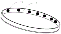
Fig. 1 is one of the perspective views of the present invention.
Fig. 2 is a second perspective view of the present invention.
Fig. 3 is an exploded view of the present invention.
Fig. 4 is a schematic partial sectional view of the present invention.
Fig. 5 is a schematic view of the half-section of the present invention.
Fig. 6 is an enlarged view of a portion a in fig. 4.
Fig. 7 is one of the installation diagrams of the present invention.
Fig. 8 is a second installation diagram of the present invention.
Fig. 9 is a third installation diagram of the present invention.
Fig. 10 is a fourth schematic view of the installation of the present invention.
Fig. 11 is a fifth installation diagram of the present invention.
Detailed Description
The features of the present invention and other related features are described in further detail below by way of examples to facilitate understanding by those skilled in the art.
In the present embodiment, it should be understood that the terms "middle", "upper", "lower", "top", "right side", "left end", "above", "back", "middle", and the like indicate orientations or positional relationships based on the orientations or positional relationships shown in the drawings, and are only for convenience of describing the present invention, and do not indicate or imply that the referred device or element must have a specific orientation, be constructed and operated in a specific orientation, and thus, should not be construed as limiting the present invention.
As shown in fig. 1 to 11, an annular lamps and lanterns convenient to light source installation, including annular rim 1 any side of annular rim 1 is equipped with mounting groove 2 be equipped with electric conductor 3 in the mounting groove 2 the 2 outsides of mounting groove are equipped with and can cover the paster 4 of 2 notches of mounting groove 1 any side of annular rim is equipped with illuminator 5 that the electric conductor 3 electricity is connected, the utility model provides a wooden rim annular ceiling lamp, annular ceiling lamp light in weight, the material of chooseing for use are cheap, and the cost of manufacture is low, and the light source installation of being convenient for uses in a flexible way, the figurative extension of lamps and lanterns of being convenient for. Can be applied to ceiling lamps or ceiling lamps.
As shown in fig. 1 and fig. 2, in the present embodiment, the light emitting device 5 may be disposed on the inner side or the outer side or the upper side or the lower side of the annular light frame 1, and is appropriately arranged according to the requirement of the lighting environment.
As shown in fig. 3, fig. 4, fig. 5, fig. 6, in this embodiment, mounting groove 2 is two, two mounting groove 2 distributes side by side on 1 lateral surface of annular rim, every set up one respectively in mounting groove 2 electric conductor 3, wooden rim is convenient for process, and is with low costs with the material, wooden rim light in weight, wooden frame give a warm sensation, are convenient for draw the distance between lamps and lanterns and the people, and wooden rim can adopt materials such as walnut, ash tree, white oak to make and form, is convenient for build graceful lighting environment.
As shown in fig. 1, fig. 2, fig. 3, fig. 4, fig. 5, and fig. 6, in this embodiment, the annular bezel 1 is a wooden bezel, the electric conductor 3 is a copper sheet, the patch 4 is a wooden patch, and an engraved pattern with a concave-convex effect may be disposed on an outer surface of the wooden patch 4, so that the annular luminaire convenient for light source installation looks more high-end atmosphere, and is convenient for creating a beautiful lighting environment.
As shown in fig. 3, fig. 4, fig. 5, fig. 6, in this embodiment, light emitting device 5 includes lamp stand 51, establishes LED lamp 52 of lamp stand 51 lateral surface, be used for with lamp stand 51 fixed mounting in connecting piece 53 on the annular lamp frame 1, connecting piece 53 is connected lamp stand 51 with between the electric conductor 3, be used for giving LED lamp 52 is electrically conductive, the utility model discloses an installation screw realizes the electricity between LED lamp pearl and the electric conductor as the terminal, has left out the installation and the cost of traditional terminal, is convenient for promote the installation effectiveness of the annular lamps and lanterns of the light source installation of being convenient for, reduces the manufacturing cost of the annular lamps and lanterns of the light source installation of being convenient for.
As shown in fig. 3, fig. 4, fig. 5, fig. 6, in this embodiment, connecting piece 53 is the screw that can electrically conduct, the utility model discloses a mounting screw realizes the electricity between LED lamp pearl and the electric conductor as the terminal, has left out the installation and the cost of traditional terminal, is convenient for promote the installation effectiveness of the annular lamps and lanterns of the light source installation of being convenient for, reduces the manufacturing cost of the annular lamps and lanterns of the light source installation of being convenient for.
As shown in fig. 7, in the present embodiment, the annular light frames 1 are formed in multiple layers, the multiple layers of the annular light frames 1 are arranged in parallel in the vertical direction, and the inner diameters of two adjacent layers of the annular light frames 1 are different, so that light rays are emitted from multiple different directions to form a complete lighting system, and a shadowless lamp is formed integrally, thereby facilitating to create a more beautiful lighting environment.
As shown in fig. 2, 3, 4, 5, and 6, in the present embodiment, the annular bezel 1 is a circular ring or an elliptical ring, and a user can select the circular ring or the elliptical ring according to different lighting environments to create a more elegant lighting environment.
As shown in fig. 2, 3, 4, 5 and 6, in the present embodiment, the ring-shaped light frame 1 is made of walnut, or fraxinus mandshurica or white oak.
As shown in fig. 2, 3, 4, 5 and 6, in this embodiment, the patch 4 is made of walnut, or fraxinus mandshurica or white oak.
As shown in fig. 8, in this embodiment, the annular light frame includes an annular light frame 1, a mounting groove 2 is disposed on an inner side surface of the annular light frame 1, a conductive body 3 is disposed in the mounting groove 2, a patch 4 capable of covering a notch of the mounting groove 2 is disposed outside the mounting groove 2, a light emitting device 5 electrically connected to the conductive body 3 is disposed on the inner side surface of the annular light frame 1, and the annular ceiling lamp is light in weight, cheap in material, low in manufacturing cost, convenient for light source installation, flexible in application, and convenient for extension of the lamp shape. Can be applied to ceiling lamps or ceiling lamps.
As shown in fig. 9, in this embodiment, the annular light frame includes an annular light frame 1, a mounting groove 2 is disposed on an inner side surface of the annular light frame 1, a conductive body 3 is disposed in the mounting groove 2, a patch 4 capable of covering a notch of the mounting groove 2 is disposed outside the mounting groove 2, a light emitting device 5 electrically connected to the conductive body 3 is disposed on the inner side surface of the annular light frame 1, 3 LED lamps are in a group, the light emitting device 5 includes multiple groups of LED lamps, the annular ceiling lamp is light in weight, cheap in material, low in manufacturing cost, convenient for light source installation, flexible in application, and convenient for extension of lamp shape. Can be applied to ceiling lamps or ceiling lamps.
As shown in fig. 10, in the present embodiment, the annular light frame includes an annular light frame 1, a mounting groove 2 is disposed on an outer side surface of the annular light frame 1, a conductive body 3 is disposed in the mounting groove 2, a patch 4 capable of covering a notch of the mounting groove 2 is disposed on an outer side surface of the mounting groove 2, a light emitting device 5 electrically connected to the conductive body 3 is disposed on an outer side surface of the annular light frame 1, a group of 3 LED lamps is provided, the light emitting device 5 includes a plurality of groups of LED lamps, the annular pendant light is light in weight, cheap in material to select, low in manufacturing cost, convenient for light source installation, flexible in application, and convenient for. Can be applied to ceiling lamps or ceiling lamps.
As shown in fig. 11, in this embodiment, the annular light frame includes an annular light frame 1, a mounting groove 2 is disposed on an outer side surface of the annular light frame 1, a conductive body 3 is disposed in the mounting groove 2, a patch 4 capable of covering a notch of the mounting groove 2 is disposed outside the mounting groove 2, a light emitting device 5 electrically connected to the conductive body 3 is disposed in the annular light frame 1, the light emitting device 5 is an LED lamp tube, and the annular pendant light is light in weight, cheap in material to select, low in manufacturing cost, convenient for light source installation, flexible in application, and convenient for extension of a lamp model. Can be applied to ceiling lamps or ceiling lamps.
As described above, the present invention provides a lighting device, and more particularly, to a ring-shaped light fixture for easy installation of a light source. The above is only the typical example of the utility model, in addition, the utility model can also have other multiple concrete implementation manners, and the technical scheme that all adopt equivalent replacement or equivalent transform to form all falls within the scope of the utility model.
Claims (9)
1. The utility model provides an annular lamps and lanterns convenient to light source installation which characterized in that: including annular rim (1) any side of annular rim (1) is equipped with mounting groove (2) be equipped with electric conductor (3) in mounting groove (2) the outside of mounting groove (2) is equipped with and covers mounting groove (2) notched paster (4) any side of annular rim (1) is equipped with illuminator (5) that electric conductor (3) electricity is connected.
2. The ring light fixture for facilitating mounting of a light source of claim 1, wherein: the mounting grooves (2) are arranged in two, the mounting grooves (2) are distributed on the outer side surface of the annular lamp frame (1) side by side, and one electric conductor (3) is arranged in each mounting groove (2).
3. The ring light fixture for facilitating mounting of a light source of claim 1, wherein: the annular lamp frame (1) is a wooden lamp frame, the electric conductor (3) is a copper sheet, and the patch (4) is a wooden patch.
4. The ring light fixture for facilitating mounting of a light source of claim 1, wherein: the light-emitting device (5) comprises a lamp holder (51), an LED lamp (52) arranged on the outer side surface of the lamp holder (51) and a connecting piece (53) used for fixedly installing the lamp holder (51) on the annular lamp frame (1), wherein the connecting piece (53) is connected between the lamp holder (51) and the conductor (3) and used for conducting electricity for the LED lamp (52).
5. The ring light fixture for facilitating mounting of a light source of claim 4, wherein: the connecting piece (53) is a conductive screw.
6. The ring light fixture for facilitating mounting of a light source of claim 1, wherein: the annular lamp frame (1) is of multiple layers, the annular lamp frames (1) are arranged in parallel in the vertical direction, and the inner diameters of the adjacent two layers of the annular lamp frames (1) are different.
7. The ring light fixture for facilitating mounting of a light source of claim 1, wherein: the annular lamp frame (1) is in a ring shape or an elliptical ring shape.
8. The ring light fixture for facilitating mounting of a light source of claim 1, wherein: the annular lamp frame (1) is made of walnut, fraxinus mandshurica or white oak.
9. The ring light fixture for facilitating mounting of a light source of claim 1, wherein: the patch (4) is made of walnut, or fraxinus mandshurica or white oak.
Priority Applications (1)
| Application Number | Priority Date | Filing Date | Title |
|---|---|---|---|
| CN202021706368.7U CN213333998U (en) | 2020-08-15 | 2020-08-15 | Annular lamp convenient for light source installation |
Applications Claiming Priority (1)
| Application Number | Priority Date | Filing Date | Title |
|---|---|---|---|
| CN202021706368.7U CN213333998U (en) | 2020-08-15 | 2020-08-15 | Annular lamp convenient for light source installation |
Publications (1)
| Publication Number | Publication Date |
|---|---|
| CN213333998U true CN213333998U (en) | 2021-06-01 |
Family
ID=76097058
Family Applications (1)
| Application Number | Title | Priority Date | Filing Date |
|---|---|---|---|
| CN202021706368.7U Expired - Fee Related CN213333998U (en) | 2020-08-15 | 2020-08-15 | Annular lamp convenient for light source installation |
Country Status (1)
| Country | Link |
|---|---|
| CN (1) | CN213333998U (en) |
-
2020
- 2020-08-15 CN CN202021706368.7U patent/CN213333998U/en not_active Expired - Fee Related
Similar Documents
| Publication | Publication Date | Title |
|---|---|---|
| US7476004B2 (en) | LED lighting lamp tube | |
| JP2010218714A (en) | Spiral led light-emitting object and led luminaire using it | |
| JP2011014515A (en) | Lighting fixture excellent on illuminance and light-distribution nature | |
| KR100945175B1 (en) | Led lighting apparatus | |
| JP3154158U (en) | Omni-directional light bulb using light-emitting diode as light source | |
| CN201621510U (en) | LED ornamental lamp | |
| JP2011216447A (en) | Led fluorescent lamp type lighting apparatus | |
| KR100945173B1 (en) | Led lighting apparatus | |
| CN201284932Y (en) | LED light source module suitable for embedded lamp shell | |
| CN201836770U (en) | LED reflector lamp convenient in heat dissipation | |
| CN101413633A (en) | Wall type LED lamp | |
| KR20190104917A (en) | Ornamental lighting appatus of stand type | |
| US20120320592A1 (en) | Multiunit and multifaceted lighting led lamp | |
| KR101069990B1 (en) | Illumination apparatus | |
| KR20110001240U (en) | Radiation module | |
| CN218153959U (en) | All-round luminous solar lamp of changeable combination | |
| CN211289611U (en) | LED decorative lamp with aluminum shell | |
| JP3175640U (en) | LED light source for three-dimensional light emitter | |
| CN104565949A (en) | 360-degree lighting multicolored intelligent bulb | |
| CN211976813U (en) | Glass LED decorative lamp | |
| CN212156733U (en) | LED filament mounting structure with adjustable illumination quantity | |
| CN201487690U (en) | Spherical LED decorative lamp string | |
| KR101130769B1 (en) | Easy assembling lighting lamp | |
| CN212226739U (en) | LED lamp with LED lamp beads capable of being increased and decreased | |
| CN205640327U (en) | A lamp post assembly and its bulb |
Legal Events
| Date | Code | Title | Description |
|---|---|---|---|
| GR01 | Patent grant | ||
| GR01 | Patent grant | ||
| CF01 | Termination of patent right due to non-payment of annual fee |
Granted publication date: 20210601 |
|
| CF01 | Termination of patent right due to non-payment of annual fee |