CN213332108U - Universal shaft for ship - Google Patents
Universal shaft for ship Download PDFInfo
- Publication number
- CN213332108U CN213332108U CN202022205199.5U CN202022205199U CN213332108U CN 213332108 U CN213332108 U CN 213332108U CN 202022205199 U CN202022205199 U CN 202022205199U CN 213332108 U CN213332108 U CN 213332108U
- Authority
- CN
- China
- Prior art keywords
- shaft
- cross
- lifting lug
- lug
- universal
- Prior art date
- Legal status (The legal status is an assumption and is not a legal conclusion. Google has not performed a legal analysis and makes no representation as to the accuracy of the status listed.)
- Active
Links
- 239000000428 dust Substances 0.000 claims abstract description 14
- 230000035939 shock Effects 0.000 claims abstract description 7
- 230000003139 buffering effect Effects 0.000 abstract description 3
- 230000006641 stabilisation Effects 0.000 abstract description 2
- 238000011105 stabilization Methods 0.000 abstract description 2
- 230000005540 biological transmission Effects 0.000 description 5
- 238000005299 abrasion Methods 0.000 description 1
- 230000009286 beneficial effect Effects 0.000 description 1
- 230000007797 corrosion Effects 0.000 description 1
- 238000005260 corrosion Methods 0.000 description 1
- 239000012535 impurity Substances 0.000 description 1
- 230000009347 mechanical transmission Effects 0.000 description 1
- 238000012986 modification Methods 0.000 description 1
- 230000004048 modification Effects 0.000 description 1
- 150000003839 salts Chemical class 0.000 description 1
- 238000006467 substitution reaction Methods 0.000 description 1
- XLYOFNOQVPJJNP-UHFFFAOYSA-N water Chemical compound O XLYOFNOQVPJJNP-UHFFFAOYSA-N 0.000 description 1
Images
Landscapes
- Sealing Devices (AREA)
Abstract
The utility model provides a universal shaft for a ship, which comprises a connecting shaft, a connecting cylinder, a cross shaft, a connecting end seat and a dustproof ring, wherein the connecting shaft is connected in the connecting cylinder; the end parts of the connecting shaft and the connecting cylinder are respectively provided with a first lifting lug, and the two ends of the cross shaft along the first direction are rotatably connected into the first lifting lugs. Can be used to prevent through the dirt ring of connecting in the cross axle end that outside debris or dust from getting into via the clearance of cross axle and lug junction, guarantee the job stabilization nature and the dustproof performance of cross axle in the universal shaft, can realize taking place the buffering of axial impact to first lug through the shock pad that sets up on the support step of second lug, and then prevent to produce great impact to the adapting unit of universal shaft, improve the safety protection performance of universal shaft.
Description
Technical Field
The utility model relates to a mechanical transmission technical field especially relates to an universal shaft for boats and ships.
Background
The universal shaft is one of important transmission parts in the field of ships, and because the power transmission torque of the ships is large, axial impact is easily caused at the joint of the universal shaft due to transmission faults or damage of parts, and because the universal shaft belongs to rotary connection, the universal shaft can be greatly damaged if axial impact occurs; moreover, the universal shaft applied to ship equipment has a severe working environment, and dust and water vapor with high salt content in the environment can have great influence on transmission parts in the universal shaft, particularly the joint of the cross shaft, so that the universal shaft is easy to cause abrasion or corrosion problems.
SUMMERY OF THE UTILITY MODEL
In view of the above, the present invention provides a universal shaft for a ship, which includes a connecting shaft, a connecting cylinder, a cross shaft, a connecting end seat and a dust ring;
the connecting shaft is connected in the connecting cylinder;
the end parts of the connecting shaft and the connecting cylinder are respectively provided with a first lifting lug, and two ends of the cross shaft along a first direction are rotatably connected into the first lifting lugs;
the connecting end seat is provided with a second lifting lug, two ends of the cross shaft along a second direction are rotatably connected into the second lifting lug, and the first direction is vertical to the second direction;
and the outer walls of the shaft ends of the cross shaft in the first direction and the second direction are respectively provided with connecting threads, the dustproof ring is sleeved on the end part of the cross shaft and is internally provided with threads, the dustproof ring is in threaded connection with the shaft end of the cross shaft, and the inner surface of the dustproof ring faces towards the outer sides of the first lifting lug and the second lifting lug.
Further, the dust ring is connected to the end of the cross shaft located in the first direction and the second direction.
Furthermore, the first lifting lug and the second lifting lug are respectively provided with a connecting hole, and the shaft end of the cross shaft is connected in the connecting hole.
Further, the inner diameter of the dustproof ring is larger than the aperture of the connecting hole.
Compared with the prior art, the utility model provides a cardan shaft for boats and ships, its beneficial effect lies in: can be used to prevent through the dirt ring of connecting in the cross axle end that outside debris or dust from getting into via the clearance of cross axle and lug junction, guarantee the job stabilization nature and the dustproof performance of cross axle in the universal shaft, can realize taking place the buffering of axial impact to first lug through the shock pad that sets up on the support step of second lug, and then prevent to produce great impact to the adapting unit of universal shaft, improve the safety protection performance of universal shaft.
Drawings
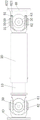
Fig. 1 is a schematic structural view of a cardan shaft for a ship according to an embodiment of the present invention.
Detailed Description
The present invention will be described in further detail with reference to the accompanying drawings and specific embodiments.
Referring to fig. 1, the present invention provides a universal shaft for a ship, which includes a connecting shaft 10, a connecting cylinder 20, a cross shaft 30, a connecting end seat 40 and a dust ring 50.
The connecting shaft 10 is connected in the connecting cylinder 20, wherein the ends of the connecting shaft 10 and the connecting cylinder 20 are respectively provided with a first lifting lug 61, and two ends of the cross shaft 30 along the first direction are rotatably connected in the first lifting lugs 61.
The connecting end seat 40 is provided with a second lifting lug 62, and two ends of the cross shaft 30 along a second direction are rotatably connected in the second lifting lug 62, wherein the first direction is perpendicular to the second direction.
The cross 30 is provided with connecting threads 31 on the outer walls of the shaft ends along the first direction and the second direction, respectively.
The dust ring 50 is sleeved on the end portion of the cross 30, threads are arranged in the dust ring 50, and the dust ring 50 is connected to the shaft end of the cross 30 in the first direction and the second direction.
The dust ring 50 is screwed with the shaft end of the cross shaft 30, and the inner surface of the dust ring 50 faces the outer sides of the first lug 61 and the second lug 62.
The first lifting lug 61 and the second lifting lug 62 are respectively provided with a connecting hole 63, the shaft end of the cross shaft 30 is connected into the connecting hole 63, and the inner diameter size of the dustproof ring 50 is larger than the aperture size of the connecting hole 63, so that the dustproof ring 50 can be used for preventing external impurities or dust from entering through a gap at the connecting part of the cross shaft 30 and the lifting lugs, and the working stability of the cross shaft 30 in the universal shaft is ensured.
The dustproof ring 50 connected to the shaft end of the cross shaft 30 can limit the cross shaft 30 to move axially along the first direction and the second direction, so that the transmission position of the cross shaft 30 is stable, the end part of the cross shaft 30 is prevented from moving axially, and the rotation stability and the rotation and stress stability of the two ends of the cross shaft 30 are ensured.
Set up on the second lug 62 and support step 621, set up shock pad 622 on the support step 621, the tip of first lug 61 corresponds with support step 621 and the butt on shock pad 622, improve the body support intensity of second lug 62 by supporting step 621 to realize buffering and protecting the axial impact of first lug 61 by shock pad 622, prevent that the too big impact of first lug 61 from leading to producing great impact damage to cross 30 and second lug 62.
Finally, it should be noted that: the above embodiments are only used to illustrate the technical solution of the present invention, and not to limit it; although the present invention has been described in detail with reference to the foregoing embodiments, it should be understood by those skilled in the art that: the technical solutions described in the foregoing embodiments may still be modified, or some technical features may be equivalently replaced; such modifications and substitutions do not depart from the spirit and scope of the present invention in its corresponding aspects.
Claims (4)
1. A universal shaft for a ship is characterized by comprising a connecting shaft, a connecting cylinder, a cross shaft, a connecting end seat and a dustproof ring;
the connecting shaft is connected in the connecting cylinder;
the end parts of the connecting shaft and the connecting cylinder are respectively provided with a first lifting lug, and two ends of the cross shaft along a first direction are rotatably connected into the first lifting lugs;
the connecting end seat is provided with a second lifting lug, two ends of the cross shaft along a second direction are rotatably connected into the second lifting lug, the first direction is vertical to the second direction, the second lifting lug is provided with a supporting step, the supporting step is provided with a shock pad, and the end part of the first lifting lug corresponds to the supporting step and is abutted against the shock pad;
and the outer walls of the shaft ends of the cross shaft in the first direction and the second direction are respectively provided with connecting threads, the dustproof ring is sleeved on the end part of the cross shaft and is internally provided with threads, the dustproof ring is in threaded connection with the shaft end of the cross shaft, and the inner surface of the dustproof ring faces towards the outer sides of the first lifting lug and the second lifting lug.
2. The universal shaft for a ship of claim 1, wherein said dust ring is connected to an end of said cross shaft in said first direction and said second direction.
3. The universal shaft for a ship according to claim 1, wherein the first lifting lug and the second lifting lug are respectively provided with a connecting hole, and a shaft end of the cross shaft is connected in the connecting hole.
4. The cardan shaft for a ship according to claim 3, wherein the inner diameter of said dust ring is larger than the diameter of said connection hole.
Priority Applications (1)
| Application Number | Priority Date | Filing Date | Title |
|---|---|---|---|
| CN202022205199.5U CN213332108U (en) | 2020-09-30 | 2020-09-30 | Universal shaft for ship |
Applications Claiming Priority (1)
| Application Number | Priority Date | Filing Date | Title |
|---|---|---|---|
| CN202022205199.5U CN213332108U (en) | 2020-09-30 | 2020-09-30 | Universal shaft for ship |
Publications (1)
| Publication Number | Publication Date |
|---|---|
| CN213332108U true CN213332108U (en) | 2021-06-01 |
Family
ID=76069292
Family Applications (1)
| Application Number | Title | Priority Date | Filing Date |
|---|---|---|---|
| CN202022205199.5U Active CN213332108U (en) | 2020-09-30 | 2020-09-30 | Universal shaft for ship |
Country Status (1)
| Country | Link |
|---|---|
| CN (1) | CN213332108U (en) |
Cited By (1)
| Publication number | Priority date | Publication date | Assignee | Title |
|---|---|---|---|---|
| CN117570150A (en) * | 2023-11-23 | 2024-02-20 | 中国水利水电第三工程局有限公司 | A kind of building electromechanical pipeline construction structure |
-
2020
- 2020-09-30 CN CN202022205199.5U patent/CN213332108U/en active Active
Cited By (1)
| Publication number | Priority date | Publication date | Assignee | Title |
|---|---|---|---|---|
| CN117570150A (en) * | 2023-11-23 | 2024-02-20 | 中国水利水电第三工程局有限公司 | A kind of building electromechanical pipeline construction structure |
Similar Documents
| Publication | Publication Date | Title |
|---|---|---|
| CN203807011U (en) | Steel wire rope anti-twisting device and tower crane | |
| CN201220580Y (en) | Steering drive axle | |
| CN203297402U (en) | Universal joint and spindle head dustproof sealing part thereof | |
| CN215805490U (en) | Steering oil cylinder of tractor | |
| CN202155848U (en) | Protective sleeve of oil seal lip | |
| CN109850071B (en) | Double-rigidity double-pretightening damping system | |
| CN217355160U (en) | Anti-loosening bolt with limiting protective sleeve | |
| CN213897252U (en) | Hydraulic connecting mechanism for movable arm of excavator | |
| CN219733787U (en) | Cylinders and operating machinery | |
| CN203285867U (en) | Control surface bearing structure | |
| CN211655562U (en) | Three-arm type high-voltage transmission line inspection robot mechanical arm | |
| CN218728221U (en) | Fiber grating with pre-twist structure | |
| CN209156723U (en) | A kind of against shock steel processing roll | |
| CN209587055U (en) | A kind of fixed shaft type speed reducer and down-the-hole drill | |
| CN108860459B (en) | A deep-sea composite structure tie-rod deformation compensation device | |
| CN217761931U (en) | Connecting structure of threaded lead screw pair | |
| CN216343346U (en) | Mechanical transmission shaft with good durability for stereo garage | |
| CN221135707U (en) | High-torsion universal sleeve | |
| CN215950183U (en) | Protective outer cover for coupler | |
| CN220600258U (en) | Joint bearing inner wall coating shielding device | |
| CN221838758U (en) | Dustproof automobile sealing ring | |
| CN208289020U (en) | Positioning device of-kind of the rotor inner hole without keyway | |
| CN111720433A (en) | High-load maintenance-free agricultural machinery hub unit | |
| CN223908162U (en) | A folding working arm for a rock drill with an external protective cover | |
| CN218613778U (en) | Broken wire removing tool |
Legal Events
| Date | Code | Title | Description |
|---|---|---|---|
| GR01 | Patent grant | ||
| GR01 | Patent grant |