CN213321485U - Ejection mechanism and injection mold - Google Patents
Ejection mechanism and injection mold Download PDFInfo
- Publication number
- CN213321485U CN213321485U CN202021407477.9U CN202021407477U CN213321485U CN 213321485 U CN213321485 U CN 213321485U CN 202021407477 U CN202021407477 U CN 202021407477U CN 213321485 U CN213321485 U CN 213321485U
- Authority
- CN
- China
- Prior art keywords
- hole
- ejection mechanism
- plate
- ejector pin
- ejector
- Prior art date
- Legal status (The legal status is an assumption and is not a legal conclusion. Google has not performed a legal analysis and makes no representation as to the accuracy of the status listed.)
- Active
Links
- 230000007246 mechanism Effects 0.000 title claims abstract description 31
- 238000002347 injection Methods 0.000 title claims abstract description 17
- 239000007924 injection Substances 0.000 title claims abstract description 17
- 230000000149 penetrating effect Effects 0.000 claims abstract description 4
- 238000000034 method Methods 0.000 description 10
- 230000000694 effects Effects 0.000 description 9
- 230000008901 benefit Effects 0.000 description 7
- 230000008569 process Effects 0.000 description 7
- 238000001746 injection moulding Methods 0.000 description 6
- 239000000243 solution Substances 0.000 description 5
- 238000004519 manufacturing process Methods 0.000 description 3
- 238000004512 die casting Methods 0.000 description 2
- 238000003723 Smelting Methods 0.000 description 1
- 230000009471 action Effects 0.000 description 1
- 238000000071 blow moulding Methods 0.000 description 1
- 238000005520 cutting process Methods 0.000 description 1
- 238000010586 diagram Methods 0.000 description 1
- 238000001125 extrusion Methods 0.000 description 1
- 238000005242 forging Methods 0.000 description 1
- 238000009776 industrial production Methods 0.000 description 1
- 238000012986 modification Methods 0.000 description 1
- 230000004048 modification Effects 0.000 description 1
- 238000000465 moulding Methods 0.000 description 1
- 238000006467 substitution reaction Methods 0.000 description 1
- 230000003746 surface roughness Effects 0.000 description 1
Images



Landscapes
- Moulds For Moulding Plastics Or The Like (AREA)
Abstract
The utility model provides an ejection mechanism and an injection mold, relating to the technical field of molds, wherein the ejection mechanism comprises an ejector pin, a protection pin, an ejector pin plate, an inclined guide post and a slide block; the ejector pin and the protection pin are fixedly connected to the ejector pin plate and can reciprocate along the longitudinal direction under the driving of the ejector pin plate; the inclined guide post is fixedly connected to the upper template and is arranged in an inclined manner from the upper template to the lower template; the slide block is connected with the inclined guide post in a sliding manner and can transversely reciprocate on the inclined guide post under the driving of the lower template, and the slide block is provided with a back hole for penetrating the protection needle; the protection needle and the retreat hole can be arranged in a staggered mode in a mold closing in-place state, and can be coaxially arranged in a mold opening in-place state. The injection mold comprises an ejection mechanism. Through the ejection mechanism, the technical problem that the ejector pin and the sliding block collide easily due to the fact that a mold with the ejector pin arranged below the sliding block in the prior art is solved.
Description
Technical Field
The utility model belongs to the technical field of the mould technique and specifically relates to an ejection mechanism and injection mold are related to.
Background
The mould is various moulds and tools for obtaining required products by injection molding, blow molding, extrusion, die casting or forging forming, smelting, stamping and other methods in industrial production. In short, a mold is a tool used to make a shaped article, the tool being made up of various parts, different molds being made up of different parts.
The die has a specific contour or cavity shape, and the blank can be separated (blanked) according to the contour shape by applying the contour shape with the cutting edge. The blank can obtain a corresponding three-dimensional shape by using the shape of the inner cavity. The mold generally comprises a movable mold and a fixed mold (or a male mold and a female mold), which can be separated or combined. When the blank is closed, the blank is injected into the die cavity for forming. The die is a precise tool, has a complex shape, bears the expansion force of a blank, has higher requirements on structural strength, rigidity, surface hardness, surface roughness and processing precision, and the development level of die production is one of important marks of the mechanical manufacturing level.
Injection molding is a method for producing and molding industrial products. The products are generally produced by rubber injection molding and plastic injection molding. The injection molding can be classified into injection molding and die casting. An injection mold is one type of mold. However, in the case of a mold having an ejector pin below a slide block, the ejector pin is likely to collide with the slide block.
SUMMERY OF THE UTILITY MODEL
An object of the utility model is to provide an ejection mechanism and injection mold to alleviate the mould that exists among the prior art and be equipped with the thimble to the slider below, take place the technical problem that thimble and slider collided easily.
In a first aspect, an embodiment of the present invention provides an ejection mechanism, which is disposed in a mold, and includes an ejector pin, a protection pin, an ejector pin plate, an inclined guide post, and a slider;
the ejector pins and the protection pins are fixedly connected to the ejector pin plate and can reciprocate along the longitudinal direction under the driving of the ejector pin plate;
the inclined guide post is fixedly connected to the upper template and is arranged in an inclined manner from the upper template to the lower template;
the slide block is connected with the inclined guide post in a sliding manner and can transversely reciprocate on the inclined guide post under the driving of the lower template, and a retreat hole for penetrating the protection needle is formed in the slide block;
the protection needle and the position withdrawing hole can be arranged in a staggered mode in a mold closing in-place state and can be coaxially arranged in a mold opening in-place state.
Furthermore, the sliding block is provided with a first bottom surface and a second bottom surface, and the position of the first bottom surface is higher than the position of the second bottom surface;
the retreating hole is a vertical through hole, and an orifice of the retreating hole is formed in the first bottom surface;
the protection needle can be in second bottom surface position department with the second bottom surface butt, and with the dislocation set.
Further, the distance between the protection needle in the mold closing in-place state and the hole opening of the back-place hole is smaller than the longitudinal moving distance of the ejector pin when a product is ejected.
Further, the sliding block comprises a body and a boss, and the boss protrudes out of part of the bottom surface of the body;
the bottom surface of the boss forms the second bottom surface.
Furthermore, the backing hole is a circular hole, and the protection needle is a cylindrical rod matched with the circular hole.
Furthermore, the number of the inclined guide columns is two, and the inclination angles of the two inclined guide columns are the same.
Furthermore, the ejection mechanism further comprises a shovel machine, and the shovel machine is fixedly connected to the upper template;
the surfaces of the shoveling machine, which are in contact with the sliding block, are inclined planes, and the inclination angles of the inclined planes are the same as those of the inclined guide columns.
Furthermore, the ejector plate comprises an ejector base plate and an ejector pin panel fixedly connected to the ejector base plate;
and a step hole used for clamping the lower end part of the thimble is formed in the thimble panel.
Further, the lower die plate is connected with a lower fixing plate through a vertical plate, and a avoidance hole is formed in the lower fixing plate;
the output end of the driving device penetrates through the avoiding hole and is used for being fixedly connected with the ejector pin bottom plate.
Has the advantages that:
the utility model provides an ejection mechanism which comprises an ejector pin, a protection pin, an ejector pin plate, an inclined guide post and a slide block; in the process of die assembly, the lower die plate drives the sliding block to move transversely on the inclined guide post, so that the protection needle and the position withdrawing hole can be arranged in a staggered mode in a die assembly in-place state, and at the moment, the ejector pin plate cannot be pushed due to the existence of the protection needle, so that the ejector pin cannot be contacted with the sliding block, and a certain protection effect can be achieved on the ejector pin; similarly, in the process of die sinking, the lower template will drive the slider on oblique guide pillar lateral motion, make protection needle and the hole of moving back both can be coaxial setting under the die sinking state of targetting in place, at this moment, promote the thimble board, protection needle on the thimble board will insert the hole of moving back, until making the thimble release the product, at this in-process, if the die sinking does not put in place, even promote the thimble board, because the existence of protection needle, will not make thimble and slider contact, play certain guard action to the thimble. According to the above, in the mold closing and opening states, the ejector pin can be prevented from colliding with the slide block due to the existence of the protection pin, and the ejector pin can be protected to a certain extent.
In a second aspect, an embodiment of the present invention provides an injection mold, including: the ejection mechanism of any of the preceding embodiments.
Has the advantages that:
the utility model provides an injection mold includes aforementioned ejection mechanism, consequently, technical advantage and effect that this injection mold reached include technical advantage and effect that ejection mechanism reached equally, and here is no longer repeated.
Drawings
In order to more clearly illustrate the embodiments of the present invention or the technical solutions in the prior art, the drawings used in the embodiments or the technical solutions in the prior art will be briefly described below, and it is obvious that the drawings in the following description are some embodiments of the present invention, and for those skilled in the art, other drawings can be obtained according to these drawings without creative efforts.
Fig. 1 is a schematic structural view of an ejection mechanism according to an embodiment of the present invention, in which a mold is in a mold closing state;
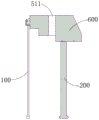
fig. 2 is a schematic structural diagram of an ejector mechanism provided in an embodiment of the present invention, in which an ejector plate is not shown, wherein a mold is in a mold closing state;
FIG. 3 is a cross-sectional view of the ejector pin, the slider and the protection pin in a state of being assembled in place;
fig. 4 is a sectional view of the thimble, the slider and the protection needle in a state of opening the mold in place.
Icon:
100-ejector pins; 200-a protection needle; 300-an ejector plate; 400-an inclined guide post; 500-a slide block; 600-shovel machine;
310-thimble base plate; 320-ejector pin panel;
510-a body; 520-a boss; 511-retreat hole; 512-a first bottom surface; 521-second bottom surface.
Detailed Description
In order to make the objects, technical solutions and advantages of the embodiments of the present invention clearer, the embodiments of the present invention will be clearly and completely described below with reference to the accompanying drawings in the embodiments of the present invention, and it is obvious that the described embodiments are some, but not all, embodiments of the present invention. The components of embodiments of the present invention, as generally described and illustrated in the figures herein, may be arranged and designed in a wide variety of different configurations.
Thus, the following detailed description of the embodiments of the present invention, presented in the accompanying drawings, is not intended to limit the scope of the invention, as claimed, but is merely representative of selected embodiments of the invention. Based on the embodiments in the present invention, all other embodiments obtained by a person skilled in the art without creative efforts belong to the protection scope of the present invention.
It should be noted that: like reference numbers and letters refer to like items in the following figures, and thus, once an item is defined in one figure, it need not be further defined and explained in subsequent figures.
In the description of the present invention, it should be noted that the terms "center", "upper", "lower", "left", "right", "vertical", "horizontal", "inner", "outer", and the like indicate the position or positional relationship based on the position or positional relationship shown in the drawings, or the position or positional relationship which is usually placed when the product of the present invention is used, and are only for convenience of description and simplification of the description, but do not indicate or imply that the device or element referred to must have a specific position, be constructed and operated in a specific orientation, and thus, should not be construed as limiting the present invention. Furthermore, the terms "first," "second," "third," and the like are used solely to distinguish one from another and are not to be construed as indicating or implying relative importance.
Furthermore, the terms "horizontal", "vertical" and the like do not imply that the components are required to be absolutely horizontal or pendant, but rather may be slightly inclined. For example, "horizontal" merely means that the direction is more horizontal than "vertical" and does not mean that the structure must be perfectly horizontal, but may be slightly inclined.
In the description of the present invention, it should also be noted that, unless otherwise explicitly specified or limited, the terms "disposed," "mounted," "connected," and "connected" are to be construed broadly, e.g., as meaning either a fixed connection, a removable connection, or an integral connection; can be mechanically or electrically connected; they may be connected directly or indirectly through intervening media, or they may be interconnected between two elements. The specific meaning of the above terms in the present invention can be understood in specific cases to those skilled in the art.
Some embodiments of the present invention will be described in detail below with reference to the accompanying drawings. The embodiments described below and the features of the embodiments can be combined with each other without conflict.
The present embodiment provides an ejection mechanism, which is disposed in a mold, and as shown in fig. 1, the ejection mechanism includes an ejector pin 100, a protection pin 200, an ejector pin plate 300, an inclined guide column 400, and a slider 500; the ejector pins 100 and the protection pins 200 are fixedly connected to the ejector plate 300 and can reciprocate along the longitudinal direction under the driving of the ejector plate 300; the inclined guide post 400 is fixedly connected to an upper template (not shown in the drawing), and the inclined guide post 400 is obliquely arranged outwards from the upper template to a lower template (not shown in the drawing); the sliding block 500 is connected with the inclined guide post 400 in a sliding manner and can move back and forth on the inclined guide post 400 under the driving of the lower template, and a retreat hole 511 for penetrating the protection needle 200 is formed in the sliding block 500; the protection needle 200 and the retreat hole 511 can be arranged in a staggered manner in a mold closing in-place state and can be coaxially arranged in a mold opening in-place state.
As shown in fig. 3 and 4, in the process of mold closing, the lower mold plate drives the slider 500 to move laterally on the inclined guide post 400, so that the protection pin 200 and the retreat hole 511 can be arranged in a staggered manner in the in-place mold closing state (see fig. 3 in particular), at this time, because of the existence of the protection pin 200, the ejector pin plate 300 cannot be pushed, the ejector pin 100 is not contacted with the slider 500, and a certain protection effect can be exerted on the ejector pin 100; similarly, in the process of opening the mold, the lower template will drive the slider to move in the opposite direction on the inclined guide post 400, so that the protection pin 200 and the retreat hole 511 can be coaxially arranged in the in-place state of opening the mold (see fig. 4 in particular), at this time, the ejector plate 300 is pushed, the protection pin 200 on the ejector plate 300 will be inserted into the retreat hole 511 until the ejector pin 100 pushes out the product, in this process, if the mold opening is not in place, even if the ejector plate 300 is pushed, the ejector pin 100 will not be in contact with the slider 500 due to the existence of the protection pin 200, and a certain protection effect is exerted on the ejector pin 100. As can be seen from the above description, in the mold closing and mold opening states, the existence of the protection pin 200 can prevent the thimble 100 from colliding with the slider 500, and can provide a certain protection effect for the thimble 100.
It should be noted that, in the present embodiment, the above-mentioned "transverse direction" refers to a direction perpendicular to the mold opening/closing direction, and also refers to a direction of lateral movement, i.e., a direction of movement of the slide 500 to the right or left in fig. 1; the "longitudinal direction" mentioned above in this embodiment refers to the opening/closing direction, which is the direction in which the slide 500 moves upward or downward as shown in fig. 1.
It should be noted that, during die assembly, the upper die plate is kept still, and the lower die plate moves upwards; when the mold is opened, the upper template is kept still, and the lower template moves downwards. In the process of the movement of the lower template, the lower template can drive the sliding block 500 to move back and forth on the inclined guide post 400, so that the relative positions of the protection needle 200 and the retreat hole 511 are changed, namely the protection needle and the retreat hole can be arranged in a staggered manner in a matched die in-place state, and can be coaxially arranged in a die opening in-place state.
As shown in fig. 2 and 3, the slider 500 has a first bottom surface 512 and a second bottom surface 521, the first bottom surface 512 being located at a higher position than the second bottom surface 521; the retreat hole 511 is a vertical through hole, and the orifice of the retreat hole 511 is arranged on the first bottom surface 512; the protection needle 200 can abut against the second bottom surface 521 at the position of the second bottom surface 521 and can be displaced from the retreat hole 511.
In this embodiment, the distance between the protection pin 200 in the mold clamping in-position state and the hole of the position-withdrawing hole 511 is smaller than the longitudinal movement distance of the thimble 100 when ejecting the product. With the arrangement, the protection needle 200 can be inserted into the retreat hole 511 in the process of ejecting a product, and a certain guiding effect can be achieved on the movement of the ejector pin 100.
As shown in fig. 2, in one embodiment of the present application, the slider 500 includes a body 510 and a boss 520, the boss 520 protruding from a portion of the bottom surface of the body 510; the bottom surface of the boss 520 forms a second bottom surface 521.
In this embodiment, the receding hole 511 is a circular hole, and the protection needle 200 is a cylindrical rod that is engaged with the receding hole 511.
As shown in fig. 1 or 2, there are two inclined guide posts 400, and the inclination angles of the two inclined guide posts 400 are the same.
With continued reference to fig. 1 or fig. 2, the ejection mechanism further includes a shovel 600, and the shovel 600 is fixedly connected to the upper template; the contact surfaces of the shovel machine 600 and the slider 500 are inclined planes, and the inclination angle of the inclined planes is the same as that of the inclined guide column 400.
As shown in fig. 1, the ejector plate 300 includes an ejector retainer plate 310 and an ejector pin plate 320 fixedly connected to the ejector retainer plate 310; the thimble panel 320 is provided with a stepped hole for engaging with the lower end of the thimble 100.
On the basis of the above embodiment, the lower die plate is connected with a lower fixing plate (not shown in the figures) through a vertical plate (not shown in the figures), and the lower fixing plate (not shown in the figures) is provided with a avoidance hole; the output end of the driving device (not shown in the figures) passes through the avoiding hole (not shown in the figures) for being fixedly connected with the thimble base plate 310.
In operation, the driving device can drive the thimble base plate 310 to move upward or downward, so that the thimble base plate 310 drives the thimble panel 320, the thimble 100 and the protection needle 200 to move upward or downward.
The embodiment also provides an injection mold, which comprises the ejection mechanism. The injection mold provided by the embodiment includes the ejection mechanism, and therefore, the technical advantages and effects achieved by the injection mold also include the technical advantages and effects achieved by the ejection mechanism, and further description is omitted here.
It should be noted that the injection mold of the present embodiment can be obtained by improving an injection mold in the prior art, that is, by adding the protection pin 200 on the basis of an existing injection mold.
Finally, it should be noted that: the above embodiments are only used to illustrate the technical solution of the present invention, and not to limit the same; although the present invention has been described in detail with reference to the foregoing embodiments, it should be understood by those skilled in the art that: the technical solutions described in the foregoing embodiments may still be modified, or some or all of the technical features may be equivalently replaced; such modifications and substitutions do not depart from the spirit and scope of the present invention.
Claims (9)
1. An ejection mechanism is arranged on a mold and is characterized by comprising an ejector pin (100), a protection pin (200), an ejector pin plate (300), an inclined guide post (400) and a slide block (500);
the ejector pins (100) and the protection pins (200) are fixedly connected to the ejector plate (300) and can reciprocate along the longitudinal direction under the driving of the ejector plate (300);
the inclined guide post (400) is fixedly connected to the upper template, and the inclined guide post (400) is obliquely arranged from the upper template to the lower template;
the sliding block (500) is connected with the inclined guide post (400) in a sliding manner and can be driven by the lower template to transversely reciprocate on the inclined guide post (400), and a retreat hole (511) for penetrating the protection needle (200) is formed in the sliding block (500);
the protection needle (200) and the retreat hole (511) can be arranged in a staggered manner in a mold closing in-place state and can be coaxially arranged in a mold opening in-place state;
the sliding block (500) is provided with a first bottom surface (512) and a second bottom surface (521), and the position of the first bottom surface (512) is higher than the position of the second bottom surface (521);
the receding hole (511) is a vertical through hole, and the orifice of the receding hole (511) is formed in the first bottom surface (512);
the protection needle (200) can abut against the second bottom surface (521) at the position of the second bottom surface (521) and can be arranged in a staggered manner with respect to the retreat hole (511).
2. The ejection mechanism according to claim 1, wherein a distance between the protection pin (200) in a mold clamping in-position state and an orifice of the retreat hole (511) is smaller than a longitudinal movement distance of the ejector pin (100) when ejecting a product.
3. The ejection mechanism of claim 1, wherein the slider (500) includes a body (510) and a boss (520), the boss (520) protruding from a portion of a bottom surface of the body (510);
the bottom surface of the boss (520) forms the second bottom surface (521).
4. The ejection mechanism according to claim 1, wherein the receding hole (511) is a circular hole, and the protection needle (200) is a cylindrical rod fitted with the circular hole.
5. The ejection mechanism according to claim 1, wherein the number of the oblique guide posts (400) is two, and the oblique angles of the two oblique guide posts (400) are the same.
6. The ejection mechanism of any of claims 1-5, further comprising a shovel (600), the shovel (600) being fixedly attached to the upper platen;
the surfaces of the shovel machine (600) and the sliding block (500) which are in contact are inclined planes, and the inclined angle of each inclined plane is the same as that of the inclined guide pillar (400).
7. The ejection mechanism according to any one of claims 1 to 5, wherein the ejector plate (300) includes an ejector retainer plate (310) and an ejector pin panel (320) fixedly connected to the ejector retainer plate (310);
and a step hole used for clamping the lower end part of the thimble (100) is formed in the thimble panel (320).
8. The ejection mechanism according to claim 7, wherein the lower die plate is connected with a lower fixing plate through a vertical plate, and the lower fixing plate is provided with an avoidance hole;
the output end of the driving device penetrates through the avoiding hole and is fixedly connected with the ejector pin bottom plate (310).
9. An injection mold, comprising: the ejection mechanism of any one of claims 1-8.
Priority Applications (1)
| Application Number | Priority Date | Filing Date | Title |
|---|---|---|---|
| CN202021407477.9U CN213321485U (en) | 2020-07-16 | 2020-07-16 | Ejection mechanism and injection mold |
Applications Claiming Priority (1)
| Application Number | Priority Date | Filing Date | Title |
|---|---|---|---|
| CN202021407477.9U CN213321485U (en) | 2020-07-16 | 2020-07-16 | Ejection mechanism and injection mold |
Publications (1)
| Publication Number | Publication Date |
|---|---|
| CN213321485U true CN213321485U (en) | 2021-06-01 |
Family
ID=76089313
Family Applications (1)
| Application Number | Title | Priority Date | Filing Date |
|---|---|---|---|
| CN202021407477.9U Active CN213321485U (en) | 2020-07-16 | 2020-07-16 | Ejection mechanism and injection mold |
Country Status (1)
| Country | Link |
|---|---|
| CN (1) | CN213321485U (en) |
Cited By (1)
| Publication number | Priority date | Publication date | Assignee | Title |
|---|---|---|---|---|
| CN115302723A (en) * | 2022-07-31 | 2022-11-08 | 东风汽车集团股份有限公司 | Injection mold capable of preventing sliding block from colliding with ejector pin and injection molding method thereof |
-
2020
- 2020-07-16 CN CN202021407477.9U patent/CN213321485U/en active Active
Cited By (1)
| Publication number | Priority date | Publication date | Assignee | Title |
|---|---|---|---|---|
| CN115302723A (en) * | 2022-07-31 | 2022-11-08 | 东风汽车集团股份有限公司 | Injection mold capable of preventing sliding block from colliding with ejector pin and injection molding method thereof |
Similar Documents
| Publication | Publication Date | Title |
|---|---|---|
| CN110549568B (en) | Demolding mechanism with back-off product | |
| CN117067525A (en) | Multi-directional cylinder core-pulling mold for complex products | |
| CN215396646U (en) | A mold with a secondary ejection mechanism | |
| CN210651713U (en) | Prevent that thimble from pushing up mould structure of hitting slider | |
| CN215544164U (en) | Take cut-out press of waste material guide structure | |
| CN222832290U (en) | Mould with two-way loose core | |
| CN219028347U (en) | Anti-collision mechanism in ejection die | |
| CN213797907U (en) | Shell part injection mold easy to demould | |
| CN221339396U (en) | Multidirectional oil cylinder core-pulling mold for complex product | |
| CN210362293U (en) | Built-in thimble core-pulling structure of injection mold | |
| CN211389852U (en) | Double-color die for game rocking bar | |
| CN214644256U (en) | Punching die for special-shaped pipe | |
| CN113134948A (en) | Mould with secondary ejection mechanism | |
| CN211165131U (en) | Large-angle inclined core-pulling mechanism of automobile column interior trimming panel mold | |
| KR102027476B1 (en) | Die-casting mold contains upper ejecting structure for deformation prevention of molded product | |
| CN222201546U (en) | Floor brush base mold of floor sweeping machine | |
| KR101975772B1 (en) | Die-casting mold contains upper ejecting structure for deformation prevention of molded product | |
| CN214820518U (en) | Mold for realizing bottom core pulling and inner wall core pulling by utilizing ejection mechanism | |
| CN108859017B (en) | Injection mold capable of rapidly opening and closing mold | |
| CN222830506U (en) | Mechanism for continuously positioning in stamping die forming process | |
| CN221417333U (en) | Blower housing mould | |
| CN217169548U (en) | Forming die of scanning rifle | |
| CN221249726U (en) | Sliding block ejection demolding structure | |
| CN215882412U (en) | Forming die of guard shield | |
| CN219486470U (en) | Double ejection mechanism |
Legal Events
| Date | Code | Title | Description |
|---|---|---|---|
| GR01 | Patent grant | ||
| GR01 | Patent grant |