CN213312111U - Paediatrics intensive care unit waste liquid collection device - Google Patents
Paediatrics intensive care unit waste liquid collection device Download PDFInfo
- Publication number
- CN213312111U CN213312111U CN202020418141.6U CN202020418141U CN213312111U CN 213312111 U CN213312111 U CN 213312111U CN 202020418141 U CN202020418141 U CN 202020418141U CN 213312111 U CN213312111 U CN 213312111U
- Authority
- CN
- China
- Prior art keywords
- lifting
- waste liquid
- fixedly connected
- collecting
- intensive care
- Prior art date
- Legal status (The legal status is an assumption and is not a legal conclusion. Google has not performed a legal analysis and makes no representation as to the accuracy of the status listed.)
- Expired - Fee Related
Links
- 239000007788 liquid Substances 0.000 title claims abstract description 70
- 239000002699 waste material Substances 0.000 title claims abstract description 59
- 230000000149 penetrating effect Effects 0.000 claims abstract description 9
- XLYOFNOQVPJJNP-UHFFFAOYSA-N water Substances O XLYOFNOQVPJJNP-UHFFFAOYSA-N 0.000 claims description 32
- 238000004659 sterilization and disinfection Methods 0.000 claims description 23
- 238000002347 injection Methods 0.000 claims description 8
- 239000007924 injection Substances 0.000 claims description 8
- 239000007921 spray Substances 0.000 claims description 8
- 230000000712 assembly Effects 0.000 claims description 7
- 238000000429 assembly Methods 0.000 claims description 7
- 231100000614 poison Toxicity 0.000 abstract description 3
- 230000007096 poisonous effect Effects 0.000 abstract description 3
- 230000001954 sterilising effect Effects 0.000 description 3
- 239000010891 toxic waste Substances 0.000 description 3
- 238000005406 washing Methods 0.000 description 3
- 238000004140 cleaning Methods 0.000 description 2
- 239000002906 medical waste Substances 0.000 description 2
- 238000000034 method Methods 0.000 description 2
- 238000012986 modification Methods 0.000 description 2
- 230000004048 modification Effects 0.000 description 2
- 238000007789 sealing Methods 0.000 description 2
- 239000000243 solution Substances 0.000 description 2
- 101100408352 Drosophila melanogaster Plc21C gene Proteins 0.000 description 1
- 230000009286 beneficial effect Effects 0.000 description 1
- 239000012141 concentrate Substances 0.000 description 1
- 230000000249 desinfective effect Effects 0.000 description 1
- 239000003814 drug Substances 0.000 description 1
- 239000012530 fluid Substances 0.000 description 1
- 239000010800 human waste Substances 0.000 description 1
- 239000000203 mixture Substances 0.000 description 1
- 238000012544 monitoring process Methods 0.000 description 1
- 230000002265 prevention Effects 0.000 description 1
- 239000000126 substance Substances 0.000 description 1
Images


Landscapes
- Apparatus For Disinfection Or Sterilisation (AREA)
Abstract
The utility model belongs to the technical field of medical equipment, in particular to a paediatrics intensive care unit waste liquid collecting device, which comprises a moving trolley, wherein the top of the moving trolley is fixedly connected with a first supporting plate and a second supporting plate, the top of the first supporting plate and the top of the second supporting plate are fixedly connected with a fixed plate, three barrel covers are arranged on the fixed plate in a penetrating way, four lifting components are arranged at the top of the moving trolley, the top of the four lifting components is fixedly connected with a lifting plate, the top of the lifting plate is provided with three weight inductors, and a collecting barrel is arranged at the top of each weight inductor; the utility model discloses, through setting up a plurality of collecting vessels, can carry out classified collection to general waste liquid, poisonous waste liquid and the waste liquid that probably contains the germ, avoid multiple waste liquid to mix, conveniently unify the processing to the waste liquid, and can carry out different clean mode to different collecting vessels, not only reduced medical personnel's probability of infecting, still reduced medical personnel's working strength.
Description
Technical Field
The utility model belongs to the technical field of medical equipment, concretely relates to paediatrics intensive care unit waste liquid collection device.
Background
Paediatrics intensive care unit has a lot of waste liquids to collect, these medical waste liquids are the human waste liquid that excretes a bit, are medical treatment medicine waste liquid a bit, and garbage bin or waste liquid collecting vessel are directly poured into to traditional treatment mode, and the sewer is emptyd again after various medical waste liquids mix, is unfavorable for the institute to feel the prevention and control, also appears the confusion easily at the in-process of collecting simultaneously, and the waste liquid of different specifications needs to be collected alone and handles according to the treatment mode of difference.
This patent provides a waste liquid collection device for paediatrics severe monitoring room can realize categorised the collection with different waste liquids, makes things convenient for the later stage to concentrate classification, also makes things convenient for medical personnel to handle the collection of waste liquid, reduces intensity of labour.
SUMMERY OF THE UTILITY MODEL
To solve the problems set forth in the background art described above. The utility model provides a paediatrics intensive care unit waste liquid collection device can realize categorised the collection with different waste liquids, makes things convenient for later stage centralized classification, also makes things convenient for medical personnel to reduce intensity of labour to the collection processing of waste liquid.
In order to achieve the above object, the utility model provides a following technical scheme: a waste liquid collecting device for pediatric intensive care units comprises a moving trolley, wherein the top of the moving trolley is fixedly connected with a first supporting plate and a second supporting plate, the top of the first supporting plate and the top of the second supporting plate are fixedly connected with a fixed plate, three barrel covers penetrate through the fixed plate, a first funnel is fixedly communicated with each barrel cover, four lifting assemblies are mounted at the top of the moving trolley, lifting plates are fixedly connected with the tops of the four lifting assemblies, hydraulic rods are fixedly mounted on the moving trolley, the driving ends of the hydraulic rods are fixedly connected to the center of the bottom of the lifting plates, three weight sensors are arranged at the tops of the lifting plates, a collecting barrel is placed at the top of each weight sensor, three through holes are formed in the tops of the lifting plates, and the three collecting barrels correspond to one barrel cover respectively, the three barrel covers are respectively buckled at the tops of the corresponding collecting barrels in a buckling mode, a connecting pipe penetrates through the top of each barrel cover, one end, penetrating through the barrel covers, of each three connecting pipe is fixedly connected with a spray head, the three connecting pipes penetrate through the through holes respectively, the bottom ends of the three connecting pipes are fixedly communicated with hoses, the top of the movable trolley is fixedly provided with a disinfection box and a water box, the top of the water box and the top of the disinfection box are respectively provided with a water injection pipe, the water box and the disinfection box are respectively internally provided with a pump body, the top of the water box is provided with a single joint, the pump body in the water box is communicated with one hose through the single joint, the top of the disinfection box is provided with a double joint, and the pump body in the disinfection box is communicated with the other two hoses through the double joint, and two electromagnetic valves are respectively arranged on the two connecting pipes connected with the two hoses communicated with the double joints.
Preferably, the left side of the first supporting plate is fixedly connected with a limiting frame, a collecting box is placed in the limiting frame, and the side face of the collecting box is fixedly communicated with a second funnel.
Preferably, the first funnel with all there is first sealed lid through hinge swing joint on the second funnel, and two the equal threaded connection in top of water injection pipe has the sealed lid of second.
Preferably, the lifting assembly comprises a fixed column fixedly mounted at the top of the moving trolley, a lifting hole is formed in the top of the fixed column, a lifting sleeve is fixedly mounted in the lifting hole, a lifting rod penetrates through the lifting sleeve, a stop block is fixedly connected to the bottom end of the lifting rod, the top end of the lifting rod is fixedly connected to the bottom of the lifting plate, and the four lifting assemblies are distributed at four corners of the bottom of the lifting plate in a rectangular shape.
Preferably, the hose is an explosion-proof soft rubber hose.
Preferably, the right side surface of the second supporting plate is fixedly connected with a storage battery, a control switch, a buzzer, a display screen and a PLC (programmable logic controller).
Preferably, the storage battery is electrically connected with the control switch through a wire, the control switch is electrically connected with the PLC through a wire, and the PLC is electrically connected with the hydraulic rod, the display screen, the electromagnetic valve, the pump body, the weight sensor and the buzzer through wires.
Preferably, the collecting box and the three collecting barrels are fixedly connected with handles on the front sides.
Compared with the prior art, the beneficial effects of the utility model are that:
the utility model discloses, through setting up a plurality of collecting vessels, can carry out classified collection to general waste liquid, poisonous waste liquid and the waste liquid that probably contains the germ, avoid multiple waste liquid to mix, the convenience is unified to the waste liquid and is handled, and through setting up water tank and disinfect box, can wash by water cleanly to the collecting vessel of collecting general waste liquid, to the collecting vessel that collects poisonous waste liquid and the waste liquid that collects probably contains the germ disinfect the disinfection and wash, can ensure medical personnel's work safety to a certain extent, staff's intensity of labour has also been alleviateed.
Drawings
The accompanying drawings are included to provide a further understanding of the invention, and are incorporated in and constitute a part of this specification, illustrate embodiments of the invention, and together with the description serve to explain the invention and not to limit the invention. In the drawings:
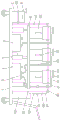
fig. 1 is a schematic structural view of a front view section of the present invention;
FIG. 2 is a front view of the present invention;
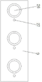
fig. 3 is a schematic structural view of the lifting plate of the present invention in a top view;
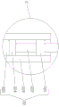
fig. 4 is an enlarged schematic structural view at a position a of the present invention;
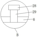
fig. 5 is an enlarged schematic structural view of the utility model at the position B;
fig. 6 is a schematic view of the internal structure of the lifting assembly of the present invention;
in the figure: 1. moving the trolley; 2. a double joint; 3. a pump body; 4. a sterilizing box; 5. a hydraulic lever; 6. a water tank; 7. a collection box; 8. a second hopper; 9. a lifting plate; 10. a first support plate; 11. a spray head; 12. a handle; 13. an electromagnetic valve; 14. a first hopper; 15. a first sealing cover; 16. a barrel cover; 17. a connecting pipe; 18. a fixing plate; 19. a display screen; 20. a control switch; 21. a PLC controller; 22. a buzzer; 23. a second support plate; 24. a storage battery; 25. a limiting frame; 26. a weight sensor; 27. a through hole; 28. a second sealing cover; 29. a water injection pipe; 30. a hose; 31. a single joint; 32. a lifting assembly; 321. a lifting sleeve; 322. a lifting rod; 323. fixing a column; 324. a stopper; 325. a lifting hole; 33. and (4) a collecting barrel.
Detailed Description
The technical solutions in the embodiments of the present invention will be described clearly and completely with reference to the accompanying drawings in the embodiments of the present invention, and it is obvious that the described embodiments are only some embodiments of the present invention, not all embodiments. Based on the embodiments in the present invention, all other embodiments obtained by a person skilled in the art without creative work belong to the protection scope of the present invention.
Examples
Referring to fig. 1-6, the present invention provides the following technical solutions: the utility model provides a paediatrics intensive care unit waste liquid collection device, includes travelling car 1, its characterized in that: the top of the moving trolley 1 is fixedly connected with a first supporting plate 10 and a second supporting plate 23, the top of the first supporting plate 10 and the top of the second supporting plate 23 are fixedly connected with a fixing plate 18, three barrel covers 16 are arranged on the fixing plate 18 in a penetrating manner, each barrel cover 16 is fixedly communicated with a first funnel 14, four lifting components 32 are arranged on the top of the moving trolley 1, each lifting component 32 comprises a fixing column 323 fixedly arranged on the top of the moving trolley 1, a lifting hole 325 is arranged on the top of the fixing column 323, a lifting sleeve 321 is fixedly arranged in each lifting hole 325, a lifting rod 322 is arranged in each lifting sleeve 321 in a penetrating manner, a stop dog 324 is fixedly connected to the bottom end of each lifting rod 322, the top end of each lifting rod 322 is fixedly connected to the bottom of the lifting plate 9, and the four lifting components 32 are distributed at four corners of the bottom of the lifting plate 9 in a rectangular manner, the top parts of the four lifting components 32 are fixedly connected with lifting plates 9, hydraulic rods 5 are fixedly mounted on the movable trolley 1, driving ends of the hydraulic rods 5 are fixedly connected to the center of the bottom part of the lifting plate 9, the hydraulic rods 5 can drive the lifting plates 9 to lift up and down, the four lifting rods 322 are driven to lift up and down synchronously when the lifting plates 9 lift up and down, so that the lifting plates 9 are kept stable, three weight sensors 26 are arranged at the top parts of the lifting plates 9, collecting barrels 33 are arranged at the top parts of the weight sensors 26, the weight sensors 26 can sense the weight of the collecting barrels 33 in real time and transmit the weight information of the collecting barrels 33 to the display screen 19 to be displayed, the lifting plates 9 can drive the three collecting barrels 33 to lift up and down, the three collecting barrels 33 are driven to be separated from the corresponding barrel covers 16 when the lifting plates 9 descend, and the corresponding collecting barrels 33 can be taken out through the handles 12, the three collecting barrels 33 correspond to one barrel cover 16 respectively, the three barrel covers 16 are buckled on the tops of the corresponding collecting barrels 33 respectively, when different waste liquids are collected, the waste liquids can be injected into the corresponding collecting barrels 33 through the first funnel 14, the top of the lifting plate 9 is provided with three through holes 27, the three collecting barrels 33 correspond to one barrel cover 16 respectively, the three barrel covers 16 are buckled on the tops of the corresponding collecting barrels 33 respectively, the top of each barrel cover 16 is provided with one connecting pipe 17 in a penetrating manner, one end of each connecting pipe 17 penetrating through the barrel cover 16 is fixedly connected with a spray head 11, the three connecting pipes 17 penetrate through the through holes 27 respectively, the bottom ends of the three connecting pipes 17 are fixedly communicated with hoses 30, and the top of the mobile trolley 1 is fixedly provided with a disinfection box 4 and a water tank 6, the top of the water tank 6 and the top of the disinfection tank 4 are both provided with a water injection pipe 29, the water tank 6 and the disinfection tank 4 are both provided with a pump body 3, the top of the water tank 6 is provided with a single joint 31, the pump body 3 in the water tank 6 is communicated with one of the hoses 30 through the single joint 31, the top of the disinfection tank 4 is provided with a double joint 2, the pump body 3 in the disinfection tank 4 is communicated with the other two hoses 30 through the double joint 2, two connecting pipes 17 connected with the two hoses 30 communicated with the double joint 2 are respectively provided with an electromagnetic valve 13, after the liquid in the water tank 6 or the disinfection tank 4 is extracted by the pump body 3, the liquid is conveyed into the hose 30 connected with the water tank through the single joint 31 or the double joint 2 and then enters the spray head 11 from the connecting pipe 17, the spray head 11 carries out washing, cleaning and disinfection on a collecting barrel 33, by providing two solenoid valves 13, it is possible to perform a separate disinfection and sterilization process for collecting toxic waste liquid or for collecting a collecting tank 33 that may contain germ waste liquid.
Specifically, the left side fixedly connected with spacing 25 of first backup pad 10, collecting box 7 has been placed in the spacing 25, collecting box 7 and three the equal fixedly connected with handle 12 in front of collecting vessel 33, the fixed intercommunication in side of collecting box 7 has second funnel 8, and when medical personnel collected the waste liquid, can meet the lower condition of some instrument leakage fluid dram that need the discharge waste liquid sometimes, and accessible collecting box 7 was collected this moment, only need take off collecting box 7 through handle 12, with the waste liquid from the injection of second funnel 8 department can.
Specifically, first funnel 14 with all there is first sealed lid 15 through hinge swing joint on the second funnel 8, through setting up first sealed lid 15, can prevent that the waste liquid from diffusing peculiar smell polluted environment, also can reduce the effluvium of harmful substance to a certain extent, and two the equal threaded connection in top of water injection pipe 29 has the sealed lid 28 of second, through setting up the sealed lid 28 of second, can prevent the liquid spill in water tank 6 and the disinfect box 4.
Specifically, the lifting assembly 32 includes a fixed column 323 fixedly mounted on the top of the moving trolley 1, a lifting hole 325 is formed in the top of the fixed column 323, a lifting sleeve 321 is fixedly mounted in the lifting hole 325, a lifting rod 322 penetrates through the lifting sleeve 321, a stop dog 324 is fixedly connected to the bottom end of the lifting rod 322, the top end of the lifting rod 322 is fixedly connected to the bottom of the lifting plate 9, and four lifting assemblies 32 are distributed at four corners of the bottom of the lifting plate 9 in a rectangular shape.
Specifically, the hose 30 is an explosion-proof flexible hose.
Specifically, the right side surface of the second supporting plate 23 is fixedly connected with a storage battery 24, a control switch 20, a buzzer 22, a display screen 19 and a PLC controller 21.
Specifically, the storage battery 24 is electrically connected with the control switch 20 through a wire, the control switch 20 is electrically connected with the PLC controller 21 through a wire, the PLC controller 21 is electrically connected with the hydraulic rod 5, the display screen 19, the electromagnetic valve 13, the pump body 3, the weight sensor 26 and the buzzer 22 through a wire, the working state of the PLC controller 21 can be controlled through the control switch 20, and the PLC controller 21 can control the working state of the hydraulic rod 5, the electromagnetic valve 13, the display screen 19, the pump body 3, the weight sensor 26 and the buzzer 22.
The utility model discloses a theory of operation and use flow: when the waste liquid is required to be collected, the movable trolley 1 is only required to be pushed to a proper position, then the waste liquid is collected into the corresponding collecting barrel 33 according to the type of the waste liquid, the three weight sensors 26 monitor the weight of the collecting barrel 33 at any time, when the weight of the collecting barrel 33 reaches a specific value, the PLC 21 controls the buzzer 22 to give an alarm, meanwhile, the weight sensors 26 display the respective weights of the three collecting barrels 33 on the display screen 19, the medical personnel can conveniently check the weights, when the collecting barrel 33 needs to be taken down, the hydraulic rod 5 is only required to be controlled to drive the lifting plate 9 to descend, when the lifting plate 9 descends, the three collecting barrels 33 can be separated from the corresponding barrel covers 16, the corresponding collecting barrels 33 can be taken out through the handles 12, the subsequent waste liquid treatment is convenient, when the collecting barrel 33 needs to be cleaned, only the pump body 3 in the water tank 6 or the disinfection tank 4 needs to be controlled to work, and the pump body 3 can pump the liquid in the water, the waste liquid is conveyed into a hose 30 connected with the single joint 31 or the double joint 2, then enters a spray head 11 from a connecting pipe 17, the spray head 11 performs washing cleaning and disinfection and sterilization on a collecting barrel 33, when medical staff collects the waste liquid, sometimes the situation that a liquid outlet of some instrument needing to discharge the waste liquid is low is encountered, the waste liquid can be collected through a collecting box 7 at the moment, the collecting box 7 only needs to be taken down through a handle 12, and the waste liquid is injected from a second funnel 8; the utility model discloses, through setting up a plurality of collecting vessel 33, can be to general waste liquid, toxic waste liquid and the waste liquid that probably contains the germ carry out categorised collection, avoid multiple waste liquid to mix, the convenience is unified to the waste liquid and is handled, and through setting up water tank 6 and disinfect box 4, can wash by water cleanly to the collecting vessel 33 of collecting general waste liquid, to collecting toxic waste liquid and collecting the collecting vessel 33 that probably contains the waste liquid of germ and disinfecting and washing, can ensure medical personnel's work safety to a certain extent, staff's intensity of labour has also been alleviateed.
Finally, it should be noted that: although the present invention has been described in detail with reference to the foregoing embodiments, it will be apparent to those skilled in the art that modifications may be made to the embodiments described in the foregoing embodiments, or equivalents may be substituted for elements thereof. Any modification, equivalent replacement, or improvement made within the spirit and principle of the present invention should be included in the protection scope of the present invention.
Claims (8)
1. The utility model provides a paediatrics intensive care unit waste liquid collection device, includes travelling car (1), its characterized in that: the top of the movable trolley (1) is fixedly connected with a first supporting plate (10) and a second supporting plate (23), the top of the first supporting plate (10) and the top of the second supporting plate (23) are fixedly connected with a fixing plate (18), three barrel covers (16) are arranged on the fixing plate (18) in a penetrating mode, each barrel cover (16) is fixedly communicated with a first funnel (14), four lifting assemblies (32) are installed at the top of the movable trolley (1), the tops of the four lifting assemblies (32) are fixedly connected with a lifting plate (9), a hydraulic rod (5) is fixedly installed on the movable trolley (1), the driving end of the hydraulic rod (5) is fixedly connected to the center of the bottom of the lifting plate (9), three weight sensors (26) are arranged at the top of the lifting plate (9), and a collecting barrel (33) is placed at the top of each weight sensor (26), the top of the lifting plate (9) is provided with three through holes (27), three collecting barrels (33) correspond to one barrel cover (16) respectively, the three barrel covers (16) are buckled on the tops of the corresponding collecting barrels (33) respectively, a connecting pipe (17) is arranged at the top of each barrel cover (16) in a penetrating mode, one end, penetrating through each barrel cover (16), of each connecting pipe (17) is fixedly connected with a spray head (11), the three connecting pipes (17) penetrate through one through hole (27) respectively, the bottom ends of the three connecting pipes (17) are fixedly communicated with hoses (30), the top of the movable trolley (1) is fixedly provided with a disinfection box (4) and a water tank (6), the top of the water tank (6) and the top of the disinfection box (4) are provided with water injection pipes (29), and pump bodies (3) are arranged in the water tank (6) and the disinfection box (4), the top of the water tank (6) is provided with a single connector (31), the pump body (3) in the water tank (6) is communicated with one of the hoses (30) through the single connector (31), the top of the disinfection tank (4) is provided with a double connector (2), the pump body (3) in the disinfection tank (4) is communicated with the other two hoses (30) through the double connector (2), and two connecting pipes (17) connected with the two hoses (30) communicated with the double connector (2) are respectively provided with an electromagnetic valve (13).
2. The paediatrics intensive care unit waste liquid collection device of claim 1, characterized in that: the left side fixedly connected with spacing (25) of first backup pad (10), collecting box (7) have been placed in spacing (25), the fixed intercommunication in side of collecting box (7) has second funnel (8).
3. The paediatrics intensive care unit waste liquid collection device of claim 2, characterized in that: first funnel (14) with all there is first sealed lid (15) through hinge swing joint on second funnel (8), and two the equal threaded connection in top of water injection pipe (29) has second sealed lid (28).
4. The paediatrics intensive care unit waste liquid collection device of claim 1, characterized in that: the lifting assembly (32) comprises a fixing column (323) fixedly mounted at the top of the movable trolley (1), a lifting hole (325) is formed in the top of the fixing column (323), a lifting sleeve (321) is fixedly mounted in the lifting hole (325), a lifting rod (322) penetrates through the lifting sleeve (321), a stop block (324) is fixedly connected to the bottom end of the lifting rod (322), the top end of the lifting rod (322) is fixedly connected to the bottom of the lifting plate (9), and the four lifting assemblies (32) are distributed at four corners of the bottom of the lifting plate (9) in a rectangular shape.
5. The paediatrics intensive care unit waste liquid collection device of claim 1, characterized in that: the hose (30) is an explosion-proof soft rubber hose.
6. The paediatrics intensive care unit waste liquid collection device of claim 1, characterized in that: the right side face of the second supporting plate (23) is fixedly connected with a storage battery (24), a control switch (20), a buzzer (22), a display screen (19) and a PLC (programmable logic controller) (21).
7. The paediatrics intensive care unit waste liquid collection device of claim 6, characterized in that: the storage battery (24) is electrically connected with the control switch (20) through a lead, the control switch (20) is electrically connected with the PLC (21) through a lead, and the PLC (21) is electrically connected with the hydraulic rod (5), the display screen (19), the electromagnetic valve (13), the pump body (3), the weight sensor (26) and the buzzer (22) through leads.
8. The paediatrics intensive care unit waste liquid collection device of claim 2, characterized in that: the front surfaces of the collection box (7) and the three collection barrels (33) are fixedly connected with handles (12).
Priority Applications (1)
| Application Number | Priority Date | Filing Date | Title |
|---|---|---|---|
| CN202020418141.6U CN213312111U (en) | 2020-03-27 | 2020-03-27 | Paediatrics intensive care unit waste liquid collection device |
Applications Claiming Priority (1)
| Application Number | Priority Date | Filing Date | Title |
|---|---|---|---|
| CN202020418141.6U CN213312111U (en) | 2020-03-27 | 2020-03-27 | Paediatrics intensive care unit waste liquid collection device |
Publications (1)
| Publication Number | Publication Date |
|---|---|
| CN213312111U true CN213312111U (en) | 2021-06-01 |
Family
ID=76057916
Family Applications (1)
| Application Number | Title | Priority Date | Filing Date |
|---|---|---|---|
| CN202020418141.6U Expired - Fee Related CN213312111U (en) | 2020-03-27 | 2020-03-27 | Paediatrics intensive care unit waste liquid collection device |
Country Status (1)
| Country | Link |
|---|---|
| CN (1) | CN213312111U (en) |
Cited By (2)
| Publication number | Priority date | Publication date | Assignee | Title |
|---|---|---|---|---|
| CN115813688A (en) * | 2022-11-04 | 2023-03-21 | 川北医学院 | A drainage fluid collection vehicle |
| CN116077755A (en) * | 2023-03-07 | 2023-05-09 | 中凡汇能有限公司 | A waste liquid collection device with self-cleaning function used in a blood replacement instrument |
-
2020
- 2020-03-27 CN CN202020418141.6U patent/CN213312111U/en not_active Expired - Fee Related
Cited By (2)
| Publication number | Priority date | Publication date | Assignee | Title |
|---|---|---|---|---|
| CN115813688A (en) * | 2022-11-04 | 2023-03-21 | 川北医学院 | A drainage fluid collection vehicle |
| CN116077755A (en) * | 2023-03-07 | 2023-05-09 | 中凡汇能有限公司 | A waste liquid collection device with self-cleaning function used in a blood replacement instrument |
Similar Documents
| Publication | Publication Date | Title |
|---|---|---|
| CN213284038U (en) | Severe clinical care ware of changing dressings | |
| CN212023674U (en) | Medical waste treatment equipment that emergency department used | |
| CN113928757B (en) | Recovery equipment for automatic disinfection of medical waste | |
| CN214716696U (en) | Waste sample treatment device for clinical examination | |
| CN213079270U (en) | Medical washing and sterilizing device | |
| CN211934937U (en) | Medical elevator safety degassing unit | |
| CN109641087A (en) | System for collecting urine | |
| CN209122939U (en) | A kind of medical cleaning and sterilization device easy to remove | |
| CN216540089U (en) | Degassing unit for biotechnology | |
| CN214813038U (en) | Gynaecology and obstetrics's nursing is with removing cleaning appliance | |
| CN215082694U (en) | Robot drip washing disinfection system | |
| CN107794212A (en) | One kind is convenient to clean type Biohazard Safety Equipment | |
| CN210847341U (en) | Medical surgical instrument disinfection device | |
| CN213678345U (en) | Paediatrics clinical medicine is with preventing infecting isolating device | |
| CN211634469U (en) | Specimen test tube preliminary disinfection processing apparatus suitable for clinical laboratory | |
| CN215438082U (en) | Medical garbage bin with disinfection function | |
| CN207738504U (en) | Fully automatic integral laboratory sewage treating machine | |
| CN216918841U (en) | A sewage treatment plant for livestock processing | |
| CN221411385U (en) | Scissors cleaning machine | |
| CN213526601U (en) | Corridor disinfection device for cardiovascular department | |
| CN110584933A (en) | A clean platform truck device for nursing of endocrine administrative or technical offices | |
| CN208193247U (en) | A kind of Medical tray frame convenient for cleaning | |
| CN220392192U (en) | Medical waste collection vehicle | |
| CN205698354U (en) | Delivery room cleaning and disinfecting vehicle | |
| CN215607800U (en) | Hemodialysis vomiting device for hematology department |
Legal Events
| Date | Code | Title | Description |
|---|---|---|---|
| GR01 | Patent grant | ||
| GR01 | Patent grant | ||
| CF01 | Termination of patent right due to non-payment of annual fee |
Granted publication date: 20210601 |
|
| CF01 | Termination of patent right due to non-payment of annual fee |