Vehicle-mounted charger with heat radiation structure
Technical Field
The utility model relates to an automobile-used charger technical field specifically is an on-vehicle charger with heat radiation structure.
Background
The vehicle-mounted charger is a vehicle-mounted charger which is powered by a conventional automobile battery (12V for cars and 24V for trucks), and is widely used in the field of lithium battery charging of various portable and handheld devices.
Such as: cell phones, PDAs, GPS, etc.; the vehicle-mounted charger not only considers the actual requirements of lithium battery charging (constant voltage CV, constant current CC and overvoltage protection OVP), but also considers the severe environment of the vehicle-mounted storage battery (transient spike voltage, system switching noise interference, EM and the like); therefore, the power management IC selected by the vehicle charging scheme must simultaneously satisfy: high voltage resistance, high efficiency, high reliability and low frequency (beneficial to the design of EMI).
The conventional vehicle-mounted charger has the condition that heat dissipation is not complete enough, and some heat dissipation structures are not sufficient in dust prevention.
In view of the above problems, an in-vehicle charger having a heat dissipation structure is proposed.
SUMMERY OF THE UTILITY MODEL
An object of the utility model is to provide an on-vehicle charger with heat radiation structure, including heat dissipation mechanism and forced air cooling mechanism, heat dissipation mechanism installs in the opposite both sides of on-vehicle charger, and forced air cooling mechanism installs in the other one side of on-vehicle charger, and the heat dissipation is more abundant, and dustproof aspect is more perfect to the problem in the background art has been solved.
In order to achieve the above object, the utility model provides a following technical scheme: a vehicle-mounted charger with a heat dissipation structure comprises a heat dissipation mechanism and an air cooling mechanism, wherein the heat dissipation mechanism is installed on two opposite sides of the vehicle-mounted charger, the air cooling mechanism is installed on the other side of the vehicle-mounted charger, the heat dissipation mechanism is provided with a first placing hole, a connecting member and a heat dissipation internal member, the first placing hole is formed in two opposite sides of the vehicle-mounted charger, the connecting member is in threaded connection with the first placing hole, and the heat dissipation internal member is installed inside the vehicle-mounted charger;
the air cooling mechanism is provided with a blowing component and a second placing hole, the blowing component is in threaded connection with the second placing hole, and the second placing hole is formed in one side of the vehicle-mounted charger.
Preferably, the first placing hole is provided with a first threaded hole, a heat dissipation hole and a first dustproof net, the first threaded hole is provided with four groups, the four groups of first threaded holes are arranged in the first placing hole, the heat dissipation hole is provided with a plurality of groups, the plurality of groups of heat dissipation holes are arranged on one side of the first placing hole, and the first dustproof net is fixedly arranged on the heat dissipation hole.
Preferably, the connecting elements is provided with dustproof net rack and first screw post, first screw post runs through dustproof net rack threaded connection in first screw hole, dustproof net rack size and the first hole size phase-match of placing.
Preferably, the heat dissipation internal member is provided with an aluminum heat dissipation fin, heat conduction silicone grease and an electronic component, wherein one side of the aluminum heat dissipation fin is fixedly arranged on one side inside the vehicle-mounted charger, the other side of the aluminum heat dissipation fin is in contact with the electronic component, the heat conduction silicone grease is arranged on one side of the aluminum heat dissipation fin in contact with the electronic component, and the electronic component is fixedly arranged inside the vehicle-mounted charger.
Preferably, the blowing member is provided with a fan case and a second screw post which is screw-coupled to the fan case.
Preferably, the second placing hole is provided with a second dustproof net and second threaded holes, the second dustproof net is installed in the center of the second placing hole, the second threaded holes are provided with four groups, and the four groups of second threaded holes are all formed in one side of the second placing hole.
Preferably, the second placing hole is matched with the blowing component in size, and the central points are located on the same vertical line.
Compared with the prior art, the beneficial effects of the utility model are as follows:
1. the utility model provides a pair of vehicle charger with heat radiation structure, electronic component through inside at vehicle charger has installed aluminium system fin in one side contact, and at aluminium system fin with one side on installed heat conduction silicone grease, make the heat that electronic component sent conduct on aluminium system fin more effectively, distribute through aluminium system fin and go in the air on every side again, and set up the first hole of placing in vehicle charger both sides, the first hole of placing sets up the heat dissipation hole of multiunit, make the steam that gives off can wave away, the radiating efficiency has been increased.
2. The utility model provides a pair of on-vehicle charger with heat radiation structure, through set up first dust screen on the heat dissipation hole, and the heat dissipation hole is set up and is first placing hole one side, make the dust of perpendicular descending can not be infected with first placing in the hole, and the dustproof rack size of setting with first placing hole size phase-match, the dustproof measure of multiple stories has ensured more can not be because of the dust damage internals that scatter in the radiating, and dustproof rack is threaded connection in first placing the hole, can easily dismantle, the change is washed, avoid the component live time too long, be infected with too much dust.
3. The utility model provides a pair of vehicle charger with heat radiation structure through set up forced air cooling mechanism in vehicle charger one side, and wherein the second place hole and the big or small phase-match of component of blowing, and the central point is in same vertical on-line, the component of blowing during operation can make aluminium system fin more high-efficient when the performance is given play to and is gone in distributing steam surrounding air, and the component of blowing itself also has the effect of cooling down vehicle charger internals, has strengthened the heat dissipation efficiency.
Drawings
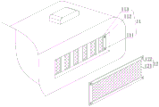
Fig. 1 is a schematic view of the overall structure of the present invention;
FIG. 2 is a schematic view of the first hole and the connecting member of the present invention;
FIG. 3 is a schematic plan view of the heat dissipation inner member of the present invention;
fig. 4 is a schematic structural view of the air cooling mechanism of the present invention.
In the figure: 1. a heat dissipation mechanism; 11. a first placing hole; 111. a first threaded hole; 112. a heat dissipation hole; 113. a first dust screen; 12. a connecting member; 121. a dustproof net rack; 122. a first threaded post; 13. a heat dissipating internal member; 131. an aluminum heat sink; 132. heat-conducting silicone grease; 133. an electronic component; 2. an air cooling mechanism; 21. a blowing member; 211. a fan frame; 212. a second threaded post; 22. a second placing hole; 221. a second dust screen; 222. and a second threaded hole.
Detailed Description
The technical solutions in the embodiments of the present invention will be described clearly and completely with reference to the accompanying drawings in the embodiments of the present invention, and it is obvious that the described embodiments are only some embodiments of the present invention, not all embodiments. Based on the embodiments in the present invention, all other embodiments obtained by a person skilled in the art without creative work belong to the protection scope of the present invention.
Referring to fig. 1, a vehicle-mounted charger with a heat dissipation structure includes a heat dissipation mechanism 1 and an air cooling mechanism 2, the heat dissipation mechanism 1 is installed on two opposite sides of the vehicle-mounted charger, and the air cooling mechanism 2 is installed on the other side of the vehicle-mounted charger.
Referring to fig. 2-3, a vehicle charger with a heat dissipation structure, a heat dissipation mechanism 1 is provided with a first placing hole 11, a connecting member 12 and a heat dissipation internal member 13, the first placing hole 11 is opened at two opposite sides of the vehicle charger, the connecting member 12 is screwed in the first placing hole 11, the heat dissipation internal member 13 is installed inside the vehicle charger, the first placing hole 11 is provided with a first screw hole 111, a heat dissipation hole 112 and a first dust screen 113, the first screw holes 111 are provided in four groups, the first screw holes 111 of the four groups are opened in the first placing hole 11, the heat dissipation hole 112 is provided in a plurality of groups, the heat dissipation holes 112 of the plurality of groups are opened at one side of the first placing hole 11, the first dust screen 113 is fixedly installed on the heat dissipation hole 112, the connecting member 12 is provided with a dust screen frame 121 and a first screw column 122, the first screw column 122 is screwed in the first screw hole 111, the size of the dustproof net frame 121 is matched with the size of the first placing hole 11, the heat dissipation internal member 13 is provided with an aluminum heat dissipation fin 131, heat conduction silicone grease 132 and an electronic element 133, one side of the aluminum heat dissipation fin 131 is fixedly arranged at one side inside the vehicle charger, the other side of the aluminum heat dissipation fin 131 is contacted with the electronic element 133, the heat conduction silicone grease 132 is arranged at one side of the aluminum heat dissipation fin 131 contacted with the electronic element 133, the electronic element 133 is fixedly arranged inside the vehicle charger, the aluminum heat dissipation fin 131 is arranged at one side of the electronic element 133 inside the vehicle charger in a contact mode, the heat conduction silicone grease 132 is arranged at the same side of the aluminum heat dissipation fin 131, the heat emitted by the electronic element 133 is more effectively conducted to the aluminum heat dissipation fin 131 and then is dissipated to the ambient air through the aluminum heat dissipation fin 131, the first placing holes 11 are arranged, make the steam that gives off can wave away, the radiating efficiency has been increased, through set up first dust screen 113 on heat dissipation hole 112, and heat dissipation hole 112 sets up and places hole 11 one side at first, make the dust of perpendicular descending can not be infected with and first place in the hole 11, and the dustproof rack 121 size and the first hole 11 size phase-match of placing that set up, the dustproof measure of more than one deck has ensured more can not be because of the dust damage internals that scatters in the radiating time, and dustproof rack 121 is threaded connection and places hole 11 first, can easily dismantle, change and wash, avoid the component live time to be of a specified duration, be infected with too much dust.
Referring to fig. 4, a vehicle charger with a heat dissipation structure, an air cooling mechanism 2 is provided with a blowing member 21 and a second placing hole 22, the blowing member 21 is screwed in the second placing hole 22, the second placing hole 22 is opened at one side of the vehicle charger, the blowing member 21 is provided with a fan frame 211 and second screw posts 212, the second screw posts 212 are screwed on the fan frame 211, the second placing hole 22 is provided with a second dust screen 221 and second screw holes 222, the second dust screen 221 is installed at the center position of the second placing hole 22, the second screw holes 222 are provided in four groups, the second screw holes 222 of the four groups are all opened at one side of the second placing hole 22, the second placing hole 22 is matched with the blowing member 21 in size, the center point is located on the same vertical line, the air cooling mechanism 2 is arranged at one side of the vehicle charger, and the second placing hole 22 is matched with the blowing member 21 in size, and the central point is in same vertical line, when blowing component 21 during operation, can make aluminium fin 131 play a role with the hot gas distribute in the surrounding air when more high-efficient, and blowing component 21 itself also has the effect of cooling to on-vehicle charger internals, has strengthened the radiating efficiency.
In summary, the following steps: the utility model discloses a vehicle charger with heat radiation structure, including heat radiation mechanism 1 and air cooling mechanism 2, heat radiation mechanism 1 is installed in the opposite both sides of vehicle charger, air cooling mechanism 2 is installed in the other side of vehicle charger, through electronic component 133 one side contact installation aluminium system fin 131 in vehicle charger, and install heat conduction silicone grease 132 on aluminium system fin 131 one side, make the heat that electronic component 133 sent more effectively conduct to aluminium system fin 131, and distribute to the surrounding air through aluminium system fin 131, and set up first placing hole 11 in vehicle charger both sides, first placing hole 11 sets up multiunit heat dissipation hole 112, make the steam of distributing can volatilize away, increased the radiating efficiency, through setting up first dust screen 113 in heat dissipation hole 112, and heat dissipation hole 112 sets up in first placing hole 11 one side, so that the dust falling vertically can not be contaminated into the first placing hole 11, the size of the dustproof net frame 121 is matched with the size of the first placing hole 11, the inner components can not be damaged by the scattered dust while the heat dissipation is ensured by the dustproof measures of a plurality of layers, the dustproof net frame 121 is in threaded connection with the first placing hole 11, can be easily disassembled, replaced and washed, avoids the components from being polluted by too much dust due to too long service time, and the air cooling mechanism 2 is arranged at one side of the vehicle-mounted charger, and the second placing hole 22 is matched with the blowing component 21 in size, and the central point is on the same vertical line, when the blowing component 21 works, the aluminum heat sink 131 can be made more efficient in functioning to dissipate hot gases into the surrounding air, and the blowing component 21 also has the function of cooling the internal components of the vehicle-mounted charger, so that the heat dissipation effect is enhanced.
It is noted that, herein, relational terms such as first and second, and the like may be used solely to distinguish one entity or action from another entity or action without necessarily requiring or implying any actual such relationship or order between such entities or actions. Also, the terms "comprises," "comprising," or any other variation thereof, are intended to cover a non-exclusive inclusion, such that a process, method, article, or apparatus that comprises a list of elements does not include only those elements but may include other elements not expressly listed or inherent to such process, method, article, or apparatus.
Although embodiments of the present invention have been shown and described, it will be appreciated by those skilled in the art that changes, modifications, substitutions and alterations can be made in these embodiments without departing from the principles and spirit of the invention, the scope of which is defined in the appended claims and their equivalents.