CN213271411U - Socket type PE water supply pipe - Google Patents
Socket type PE water supply pipe Download PDFInfo
- Publication number
- CN213271411U CN213271411U CN202022120831.6U CN202022120831U CN213271411U CN 213271411 U CN213271411 U CN 213271411U CN 202022120831 U CN202022120831 U CN 202022120831U CN 213271411 U CN213271411 U CN 213271411U
- Authority
- CN
- China
- Prior art keywords
- water supply
- pipe
- inner pipe
- groove
- socket
- Prior art date
- Legal status (The legal status is an assumption and is not a legal conclusion. Google has not performed a legal analysis and makes no representation as to the accuracy of the status listed.)
- Expired - Fee Related
Links
- XLYOFNOQVPJJNP-UHFFFAOYSA-N water Substances O XLYOFNOQVPJJNP-UHFFFAOYSA-N 0.000 title claims abstract description 86
- 230000000844 anti-bacterial effect Effects 0.000 claims abstract description 11
- 238000007789 sealing Methods 0.000 claims description 24
- VYPSYNLAJGMNEJ-UHFFFAOYSA-N Silicium dioxide Chemical compound O=[Si]=O VYPSYNLAJGMNEJ-UHFFFAOYSA-N 0.000 claims description 16
- 239000000741 silica gel Substances 0.000 claims description 16
- 229910002027 silica gel Inorganic materials 0.000 claims description 16
- 238000003466 welding Methods 0.000 claims description 2
- 241000894006 Bacteria Species 0.000 abstract description 19
- 238000009434 installation Methods 0.000 abstract description 18
- 230000002401 inhibitory effect Effects 0.000 abstract description 15
- 238000012423 maintenance Methods 0.000 abstract description 5
- 238000009395 breeding Methods 0.000 abstract description 4
- 230000001488 breeding effect Effects 0.000 abstract description 4
- 230000003111 delayed effect Effects 0.000 abstract description 3
- 239000000428 dust Substances 0.000 description 3
- 241000282414 Homo sapiens Species 0.000 description 2
- 230000003385 bacteriostatic effect Effects 0.000 description 2
- 238000011161 development Methods 0.000 description 2
- 238000004134 energy conservation Methods 0.000 description 2
- 208000032750 Device leakage Diseases 0.000 description 1
- 230000004075 alteration Effects 0.000 description 1
- 230000009286 beneficial effect Effects 0.000 description 1
- 238000010276 construction Methods 0.000 description 1
- 238000013461 design Methods 0.000 description 1
- 238000010586 diagram Methods 0.000 description 1
- 238000001035 drying Methods 0.000 description 1
- 238000005265 energy consumption Methods 0.000 description 1
- 230000007613 environmental effect Effects 0.000 description 1
- 239000012530 fluid Substances 0.000 description 1
- 239000003292 glue Substances 0.000 description 1
- 238000000034 method Methods 0.000 description 1
- 238000012986 modification Methods 0.000 description 1
- 230000004048 modification Effects 0.000 description 1
- 231100000252 nontoxic Toxicity 0.000 description 1
- 230000003000 nontoxic effect Effects 0.000 description 1
- 230000002265 prevention Effects 0.000 description 1
- 238000006467 substitution reaction Methods 0.000 description 1
- 230000004083 survival effect Effects 0.000 description 1
- 238000003911 water pollution Methods 0.000 description 1
Images


Landscapes
- Quick-Acting Or Multi-Walled Pipe Joints (AREA)
Abstract
The utility model discloses a socket joint type PE water supply pipe, which comprises a PE water supply inner pipe, wherein a first inner bacteria inhibiting layer is arranged inside the PE water supply inner pipe, the first inner antibacterial layer is fixedly connected with the PE water supply inner pipe, the outer part of the PE water supply inner pipe is provided with a plurality of outer clamping grooves, the socket type PE water supply pipe can well prevent bacteria from breeding in the device by installing the first internal bacteria inhibiting layer and the second internal bacteria inhibiting layer, the practicability of the device is improved, the device is safer to use, the limiting spring is installed to push the clamping shaft to be clamped into the external clamping groove, the device is more convenient to install, the installation efficiency of workers is prevented from being influenced, the working progress is delayed, and when carrying out pipeline maintenance, be convenient for dismantle fast, increase the practicality of device, the installation pull ring is convenient for the staff to outside stimulate the drive shaft and is convenient for the staff to install dismounting device fast.
Description
Technical Field
The utility model relates to a feed pipe technical field specifically is a socket joint formula PE feed pipe.
Background
The water supply pipe is a green, energy-saving and environment-friendly pipe, is not rusty, scaled, reduced and small in fluid resistance, can effectively reduce the energy consumption of water supply and improve the water supply quantity of water consumption points, is an ideal pipe for a pipe network, water is a life source and the basis of human civilized survival development, the water crisis has become the key point of global common attention of all human beings, and the increasingly serious water resource shortage and water environment pollution in China currently not only troubles the countryside of China, but also becomes an important factor for restricting the sustainable development of social economy. The building industry is the prop industry in China, the design, construction and maintenance of a building water supply and drainage system are well done, the method is a specific means for realizing water conservation, energy conservation and water pollution prevention and control, and the urgent requirements for energy conservation, emission reduction and environmental protection are also made;
however, the existing PE water supply pipe is inconvenient to install, the installation efficiency of workers is seriously affected, the working progress is delayed, and the PE water supply pipe is inconvenient to disassemble quickly when being repaired.
SUMMERY OF THE UTILITY MODEL
An object of the utility model is to provide a socket joint formula PE feed pipe to the PE feed pipe installation that proposes in solving above-mentioned background art is inconvenient, seriously influences staff's installation effectiveness, hinders the job schedule, and when carrying out the pipeline maintenance, is not convenient for quick problem of dismantling.
In order to achieve the above object, the utility model provides a following technical scheme: a socket joint type PE water supply pipe comprises a PE water supply inner pipe, wherein a first internal antibacterial layer is arranged inside the PE water supply inner pipe, the first internal antibacterial layer is fixedly connected with the PE water supply inner pipe, an external clamping groove is arranged outside the PE water supply inner pipe, a plurality of external clamping grooves are arranged on the external clamping grooves, a PE water supply outer pipe is arranged at one end outside the PE water supply inner pipe, a second internal antibacterial layer is arranged inside the PE water supply outer pipe, the second internal antibacterial layer is fixedly connected with the PE water supply outer pipe, an internal clamping groove is arranged on the inner side of the second internal antibacterial layer, a plurality of internal clamping grooves are arranged on the internal clamping grooves, a driving shaft is arranged inside the PE water supply outer pipe close to two ends of the upper end of one side of the PE water supply inner pipe, the driving shaft is connected with the PE water supply outer pipe in a sliding mode through clamping grooves, a clamping shaft is arranged, and a limiting spring is arranged at one end, close to the clamping shaft, of the outer part of the driving shaft.
Preferably, the upper end of the driving shaft is provided with a pull ring, and the pull ring is connected with the driving shaft in a welding manner.
Preferably, the sealing cover plates are arranged at the two ends of the upper end and the lower end of one side, close to the PE water supply inner pipe, of the outer PE water supply pipe, and the sealing cover plates are fixedly connected with the outer PE water supply pipe through clamping grooves.
Preferably, a forty-five degree chamfer is arranged at one end of the PE water supply inner pipe close to the PE water supply outer pipe.
Preferably, install leak protection sealing silica gel backing ring between outside draw-in groove and the inside draw-in groove, leak protection sealing silica gel backing ring is connected with inside draw-in groove is spliced, leak protection sealing silica gel backing ring passes through the draw-in groove with outside draw-in groove and is connected.
Preferably, the exterior of the PE water supply outer pipe is provided with frosted lines.
Compared with the prior art, the beneficial effects of the utility model are that:
1. the socket type PE water supply pipe can well prevent bacteria from breeding in the device by installing the first internal bacteria inhibiting layer and the second internal bacteria inhibiting layer, the practicability of the device is improved, the device is safer to use, the clamping shaft can be pushed to be clamped into the external clamping groove by installing the limiting spring, the device is more convenient to install, the installation efficiency of workers is prevented from being influenced, the working progress is delayed, in addition, when the pipeline maintenance is carried out, the quick disassembly is convenient, the practicability of the device is improved, the installation pull ring is convenient for the workers to pull the driving shaft outwards, and the workers can quickly install and disassemble the device;
2. this socket joint formula PE feed pipe can prevent debris such as dust and pull ring contact through the sealed apron of installation, influences staff's operative installations, can prevent simultaneously that the drive shaft is not hard up, increases the result of use of device, and the leakproofness that installation leak protection sealing silica gel backing ring can increase the device prevents that the device from leaking, increases the practicality of device.
Drawings
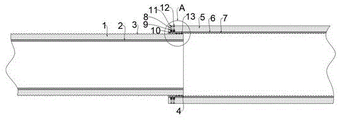
FIG. 1 is a schematic sectional view of the present invention;
FIG. 2 is a schematic view of the structure of the present invention;
FIG. 3 is an enlarged view of part A of FIG. 1;
fig. 4 is an enlarged schematic structural diagram of a portion B in fig. 2 according to the present invention.
In the figure: 1. a PE water supply inner pipe; 2. a first inner bacteriostatic layer; 3. an external card slot; 4. chamfering at forty-five degrees; 5. PE water supply outer pipe; 6. a second inner bacteriostatic layer; 7. an internal card slot; 8. a drive shaft; 9. a limiting spring; 10. clamping a shaft; 11. a pull ring; 12. sealing the cover plate; 13. leak protection sealing silica gel backing ring.
Detailed Description
The technical solutions in the embodiments of the present invention will be described clearly and completely with reference to the accompanying drawings in the embodiments of the present invention, and it is obvious that the described embodiments are only some embodiments of the present invention, not all embodiments. Based on the embodiments in the present invention, all other embodiments obtained by a person skilled in the art without creative work belong to the protection scope of the present invention.
Referring to fig. 1-4, the present invention provides a technical solution: a spigot-and-socket PE water supply pipe comprises a PE water supply inner pipe 1, a first inner bacteria inhibiting layer 2 is arranged inside the PE water supply inner pipe 1, the first inner bacteria inhibiting layer 2 and a second inner bacteria inhibiting layer 6 are arranged to well prevent bacteria from breeding inside the device, the practicability of the device is improved, the device is safer to use, the first inner bacteria inhibiting layer 2 is fixedly connected with the PE water supply inner pipe 1, an outer clamping groove 3 is arranged outside the PE water supply inner pipe 1, the outer clamping groove 3 can play a role in skid resistance, a worker can conveniently and quickly install the device, meanwhile, the device is matched with a clamping shaft 10 to play a limiting role, the worker can conveniently and quickly install the device, a plurality of outer clamping grooves 3 are arranged, a PE water supply outer pipe 5 is arranged at one end outside the PE water supply inner pipe 1, a second inner bacteria inhibiting layer 6 is arranged inside the PE water supply outer pipe 5, the second inner bacteria inhibiting layer 6 is fixedly connected with the PE water supply outer pipe 5, the inner side of the second inner bacteria inhibiting layer 6 is provided with a plurality of inner clamping grooves 7, the inner clamping grooves 7 are provided with a plurality of driving shafts 8, the inner parts of the PE water supply outer pipe 5, close to the two ends of the upper end of one side of the PE water supply inner pipe 1, are respectively provided with a driving shaft 8, the driving shafts 8 are in sliding connection with the PE water supply outer pipe 5 through clamping grooves, the lower ends of the driving shafts 8 are provided with clamping shafts 10, the clamping shafts 10 are in welded connection with the driving shafts 8, one ends, close to the clamping shafts 10, of the outer parts of the driving shafts 8 are provided with limiting springs 9, the clamping shafts 10 can be pushed to be clamped into the outer clamping grooves 3 by installing the limiting springs 9, the device is more convenient to install, the installation efficiency of;
the upper end of the driving shaft 8 is provided with a pull ring 11, the pull ring 11 is installed to facilitate a worker to pull the driving shaft 8 outwards to facilitate the worker to quickly install and detach the device, the pull ring 11 is welded with the driving shaft 8, both ends of the upper end and the lower end of one side, close to the PE water supply inner pipe 1, of the outer PE water supply pipe 5 are provided with sealing cover plates 12, the sealing cover plates 12 are fixedly connected with the outer PE water supply pipe 5 through clamping grooves, one end, close to the outer PE water supply pipe 5, of the inner PE water supply pipe 1 is provided with a forty-five-degree chamfer 4, the sealing cover plates 12 are installed to prevent dust and other sundries from contacting with the pull ring 11 to;
install leak protection sealing silica gel backing ring 13 between outside draw-in groove 3 and the inside draw-in groove 7, leak protection sealing silica gel backing ring 13 splices with inside draw-in groove 7 and is connected, and leak protection sealing silica gel backing ring 13 passes through the draw-in groove with outside draw-in groove 3 and is connected, and the outside of PE feedwater outer tube 5 is provided with the frosting line, and installation leak protection sealing silica gel backing ring 13 can increase the leakproofness of device, prevents that the device from leaking, increases the practicality of device.
The working principle is as follows: when the device is used, a worker installs the leakage-proof sealing silica gel backing ring 13 inside the external clamping groove 3, then fixes the leakage-proof sealing silica gel backing ring 13 inside the external clamping groove 3 by using quick-drying non-toxic glue, then pulls the pull ring 11 to enable the clamping shaft 10 to retract into the second internal bacteria inhibiting layer 6, then sleeves the PE water supply outer pipe 5 outside the PE water supply inner pipe 1 to enable the leakage-proof sealing silica gel backing ring 13 to be clamped inside the internal clamping groove 7, then loosens the pull ring 11, the limiting spring 9 pushes the clamping shaft 10 to enable the clamping shaft 10 to be clamped into the external clamping groove 3 to limit the PE water supply inner pipe 1 and the PE water supply outer pipe 5, the device is provided with the first internal bacteria inhibiting layer 2 and the second internal bacteria inhibiting layer 6 which can well prevent the breeding of bacteria inside the device, the practicability of the device is increased, the device is safer to use, the limiting spring 9 can push the clamping shaft 10 to be clamped into the external clamping groove, make the device installation more convenient, avoid influencing staff's installation effectiveness, hinder the job schedule, and when carrying out pipeline maintenance, be convenient for dismantle fast, increase the practicality of device, installation pull ring 11 is convenient for the staff to stimulate drive shaft 8 to the outside and is convenient for the staff to install dismounting device fast, sealed apron 12 of installation can prevent debris such as dust and pull ring 11 contact, influence staff's operative installations, can prevent simultaneously that drive shaft 8 is not hard up, increase the result of use of device, installation leak protection sealing silica gel backing ring 13 can increase the leakproofness of device, prevent the device leakage, increase the practicality of device.
Although embodiments of the present invention have been shown and described, it will be appreciated by those skilled in the art that changes, modifications, substitutions and alterations can be made in these embodiments without departing from the principles and spirit of the invention, the scope of which is defined in the appended claims and their equivalents.
Claims (6)
1. The utility model provides a socket joint formula PE feed pipe, includes PE feed water inner tube (1), its characterized in that: the water supply device is characterized in that a first internal antibacterial layer (2) is arranged inside the PE water supply inner pipe (1), the first internal antibacterial layer (2) is fixedly connected with the PE water supply inner pipe (1), an external clamping groove (3) is arranged outside the PE water supply inner pipe (1), a plurality of external clamping grooves (3) are arranged, a PE water supply outer pipe (5) is arranged at one end outside the PE water supply inner pipe (1), a second internal antibacterial layer (6) is arranged inside the PE water supply outer pipe (5), the second internal antibacterial layer (6) is fixedly connected with the PE water supply outer pipe (5), an internal clamping groove (7) is arranged on the inner side of the second internal antibacterial layer (6), a plurality of internal clamping grooves (7) are arranged in the PE water supply outer pipe (5), a driving shaft (8) is arranged inside the PE water supply outer pipe (5) close to two ends of the upper end of one side of the PE water supply inner pipe (1), and the driving shaft (8) is connected with the PE water supply outer, the lower extreme of drive shaft (8) is installed card axle (10), card axle (10) and drive shaft (8) welded connection, the outside one end that is close to card axle (10) of drive shaft (8) is provided with spacing spring (9).
2. The spigot-and-socket PE water supply pipe of claim 1, wherein: and a pull ring (11) is installed at the upper end of the driving shaft (8), and the pull ring (11) is connected with the driving shaft (8) in a welding manner.
3. The spigot-and-socket PE water supply pipe of claim 1, wherein: the PE water supply outer pipe (5) is externally provided with sealing cover plates (12) close to the upper end and the lower end of one side of the PE water supply inner pipe (1), and the sealing cover plates (12) are fixedly connected with the PE water supply outer pipe (5) through clamping grooves.
4. The spigot-and-socket PE water supply pipe of claim 1, wherein: one end of the PE water supply inner pipe (1) close to the PE water supply outer pipe (5) is provided with a forty-five degree chamfer (4).
5. The spigot-and-socket PE water supply pipe of claim 1, wherein: install leak protection sealing silica gel backing ring (13) between outside draw-in groove (3) and inside draw-in groove (7), leak protection sealing silica gel backing ring (13) is connected with inside draw-in groove (7) splice, leak protection sealing silica gel backing ring (13) is connected through the draw-in groove with outside draw-in groove (3).
6. The spigot-and-socket PE water supply pipe of claim 1, wherein: and frosted lines are arranged outside the PE water supply outer pipe (5).
Priority Applications (1)
| Application Number | Priority Date | Filing Date | Title |
|---|---|---|---|
| CN202022120831.6U CN213271411U (en) | 2020-09-24 | 2020-09-24 | Socket type PE water supply pipe |
Applications Claiming Priority (1)
| Application Number | Priority Date | Filing Date | Title |
|---|---|---|---|
| CN202022120831.6U CN213271411U (en) | 2020-09-24 | 2020-09-24 | Socket type PE water supply pipe |
Publications (1)
| Publication Number | Publication Date |
|---|---|
| CN213271411U true CN213271411U (en) | 2021-05-25 |
Family
ID=75944512
Family Applications (1)
| Application Number | Title | Priority Date | Filing Date |
|---|---|---|---|
| CN202022120831.6U Expired - Fee Related CN213271411U (en) | 2020-09-24 | 2020-09-24 | Socket type PE water supply pipe |
Country Status (1)
| Country | Link |
|---|---|
| CN (1) | CN213271411U (en) |
-
2020
- 2020-09-24 CN CN202022120831.6U patent/CN213271411U/en not_active Expired - Fee Related
Similar Documents
| Publication | Publication Date | Title |
|---|---|---|
| CN206159690U (en) | Feeding and discharging pipeline connection device | |
| CN102797939A (en) | Rapid pipeline leakage blocking device | |
| CN217402011U (en) | High-precision new-energy locomotive fluid pipe assembly | |
| CN202769173U (en) | Pipe quick leaking stoppage device | |
| CN208997506U (en) | One kind going out family pipe connections | |
| CN201723876U (en) | Quick connection type galvanized connecting pipe | |
| CN203240176U (en) | Novel anti-scouring T-type pipeline bend | |
| CN216344655U (en) | Direct drinking water pipe network repairing device without dismantling old pipeline | |
| CN223399453U (en) | Sealing structure of water supply and drainage pipeline pump | |
| CN218153021U (en) | Water supply pipe network plugging device that leaks | |
| CN203176581U (en) | Lining plastic compound steel pipe | |
| CN202834494U (en) | Pipeline connecting device | |
| CN220168879U (en) | Water leakage preventing device for pipeline | |
| CN217463585U (en) | Pipeline sealing structure for gas engineering installation | |
| CN217714014U (en) | Electromechanical water supply and drainage pipe anti-seepage device | |
| CN222351700U (en) | A pipeline sealing device for water conservancy and hydropower engineering construction | |
| CN220187126U (en) | Solar side cover fixing structure | |
| CN201810937U (en) | Novel sealing element | |
| CN206875017U (en) | A kind of emergent closure shunting device of petroleum pipeline | |
| CN221055551U (en) | Calcium carbide furnace circulating water system | |
| CN223806737U (en) | An energy-saving installation structure for municipal water supply and drainage | |
| CN223825893U (en) | A thermal pipeline insulation and energy-saving device | |
| CN218914986U (en) | Boiler waste heat utilization device | |
| CN221300451U (en) | Pipeline connecting device for building heating and ventilation heating pipeline | |
| CN201568986U (en) | Novel sealing strip used on air preheater |
Legal Events
| Date | Code | Title | Description |
|---|---|---|---|
| GR01 | Patent grant | ||
| GR01 | Patent grant | ||
| CF01 | Termination of patent right due to non-payment of annual fee | ||
| CF01 | Termination of patent right due to non-payment of annual fee |
Granted publication date: 20210525 |