Plastic product recycling and crushing system
Technical Field
The utility model belongs to the technical field of the plastic products production, especially, relate to a plastic products is retrieved and broken system.
Background
The plastic products are common materials in daily life of people, and due to the wide application of the plastic products, waste plastic products are more and more, and the waste plastic products are not easy to decompose and rot and cannot naturally disappear after being stored in a natural living environment for a long time. The waste plastics which float on the water surface, are mixed in the soil, hang on the branches and fly with the wind cause river water pollution, poison aquatic organisms and deteriorate the soil, and if the waste plastics are collected and burnt, a large amount of harmful gas is emitted to cause air pollution.
Through retrieval, patent publication No. CN 209755814U discloses a plastic product recovery and crushing system, which improves the efficiency of waste product recovery by arranging a roller crusher, reduces the dust generated during waste plastic recovery by arranging a bag-type dust collector, and in addition, the prior art is also provided with a compression spring, a limit stop, a telescopic closing plate, an electric push rod, a support rod, a material receiving cylinder and other structures to realize the blocking of the dust in the blanking process and prevent the air flow from blowing into the blanking cylinder, the complex structure is adopted only to realize the blocking of the dust and ensure the normal blanking of the waste plastic products, the problems of high manufacturing cost, easy damage and inconvenient maintenance exist, meanwhile, the prior art does not screen the crushed material products, and some plastic products which are not crushed thoroughly are easy to block a discharge channel, and is not beneficial to the subsequent recovery, and in view of the above two points, there is a need to improve the prior art to solve the above existing problems.
SUMMERY OF THE UTILITY MODEL
An object of the utility model is to provide a plastic products retrieves and broken system, through setting up the spring landing leg, the feeding dish keeps off the dirt area, go out the dish and keeps off the dirt area, screening dish and vibration exciter, feeding keeps off the dirt area and the ejection of compact keeps off the dirt area and installs respectively on the feed inlet and the discharge gate of this device, can keep off the dirt to the feeding and the ejection of compact position of broken case, reduce the outer expanding of dust, the screening dish can filter the material after the breakage, avoid not blockking up discharging channel by broken thorough plastic products whereabouts, the vibration exciter can make broken case constantly shake in crushing process with the cooperation of spring landing leg, reduce the jam, the screening dish of being convenient for simultaneously filters, it is complicated to have solved current technological dustproof construction design, the cost of manufacture is high, and not filter the material after the breakage, cause the problem of jam easily.
In order to solve the technical problem, the utility model discloses a realize through following technical scheme:
the utility model relates to a plastic product recycling and crushing system, which comprises a crushing box, spring supporting legs, a feeding disc dust blocking belt, a screening disc, a discharging disc dust blocking belt and a vibration exciter, wherein the spring supporting legs are arranged at the four corners of the bottom of the crushing box, a base is arranged at the bottom end of the spring supporting legs, the feeding disc is arranged at one side of the upper end of the crushing box, the feeding disc dust blocking belt is arranged at the joint of the feeding disc and the crushing box, a first crushing roller and a second crushing roller are symmetrically arranged in the crushing box, a roller shaft at one end of the first crushing roller and a roller shaft at one end of the second crushing roller are respectively and fixedly connected with a rotating shaft of a first crushing motor and a rotating shaft of a second crushing motor which are arranged on the outer wall of the crushing box, the screening disc is arranged under the first crushing roller and the second crushing roller, the two sides of the screening disc are in sliding connection with sliding rails which are, the utility model discloses a broken case, including broken case, feed tray, dust absorption pipe, dust catcher, vibration exciter, discharge disc and broken case junction, the bottom one side of broken case is installed out the dish and is kept off the dirt area, the dust absorption pipe is installed with the relative one side of feed tray in the upper portion of broken case, install the dust catcher on the dust absorption pipe, the bottom of dust absorption pipe is connected with the dust remover of installing on broken case outer wall, the vibration exciter is installed to the bottom of broken case.
Further, the spring landing leg includes support column, spring and connecting seat, the bottom and the base fixed connection of support column, the spring is installed to the upper end of support column, the connecting seat is installed to the upper end of spring, the top of connecting seat and the bottom fixed connection of broken case, the spring landing leg set up the vibration effect of multiplicable vibration exciter for broken material constantly shakes in broken incasement, avoids causing the jam.
Further, the screening dish includes pull board and screen cloth, the spout that uses with the slide rail cooperation is seted up to the both sides of pull board, the screen cloth is installed to the centre of screening dish, lie in the screening dish on the outer wall of broken case directly over the position and install spacing safety pin, the pull board through with broken incasement both sides on the inner wall slide connection of slide rail, can make things convenient for personnel to remove the unqualified material that is detained on the screen cloth with the screening, conveniently unload.
Further, the guide block is installed to the interior bottom of broken incasement, the up end of guide block is towards the downward sloping of ejection of compact dish direction to the lowest end height of guide block is highly unanimous with the discharge gate bottom of ejection of compact dish, and the guide block can guide the material, makes the material that falls into broken bottom of the case portion after being filtered can discharge from the ejection of compact dish smoothly.
Further, the crushing roller baffle is installed in the outside that lies in first crushing roller and second crushing roller on the inner wall of broken case, crushing roller baffle and the relative one side of crushing roller be with crushing roller assorted arcwall face, the setting up of crushing roller baffle can guide the old and useless plastic products that enter into broken incasement and move towards crushing roller direction, avoid crushing roller and broken incasement wall between the space too big and appear not broken just by the problem that spills.
Furthermore, the bottom surface of the feeding disc is gradually reduced from one end far away from the crushing box to one end connected with the crushing box, and the bottom surface of the discharging disc is gradually reduced from one end connected with the crushing box to one end far away from the crushing box.
The utility model discloses following beneficial effect has:
1. the utility model discloses a set up feeding dish and keep off the dirt area and go out the dish and keep off the dirt area, feeding dish keeps off the dirt area and goes out the dish and keep off the dirt area and install respectively on feeding dish feed inlet and on going out the dish discharge gate, it sets up side by side to keep off the dirt area, when old and useless plastic products gets into from the feeding dish, feeding dish keeps off the dirt area and can be knocked out, make old and useless plastic products passageway, just can resume the former state when old and useless plastic products keep off the dirt area through the back charging tray, it is dustproof to realize, it is also so to go out the dish and keep off the dirt area with the same reason, it adopts low-priced plastics to make to keep off the dirt area, moreover, the steam generator is simple in structure.
2. The utility model discloses a set up the screening dish, spring landing leg and vibration exciter, be provided with the screen cloth in the screening dish, can filter the waste plastic products after the breakage, vibration exciter work arouses broken case vibrations simultaneously, the spring landing leg can increase broken case vibration range, make the screening dish efficiency higher when screening, discharging channel is difficult for blockking up, the unqualified waste plastic products that the screening was detained can be unloaded it by personnel pull screening dish, it can't filter the broken unqualified waste plastic products to have solved current technique, lead to discharging channel to block up easily, use inconvenient problem.
Of course, it is not necessary for any particular product to achieve all of the above-described advantages at the same time.
Drawings
In order to more clearly illustrate the technical solutions of the embodiments of the present invention, the drawings used in the description of the embodiments will be briefly introduced below, and it is obvious that the drawings in the following description are only some embodiments of the present invention, and it is obvious for those skilled in the art that other drawings can be obtained according to these drawings without creative efforts.
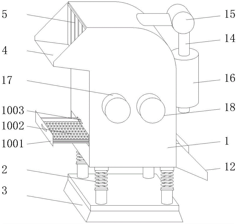
FIG. 1 is an overall appearance diagram of the present invention;
FIG. 2 is a schematic diagram of the internal structure of FIG. 1 according to the present invention;
fig. 3 is a right side view of the present invention in fig. 1;
fig. 4 is a schematic structural view of the spring leg of fig. 2 according to the present invention.
In the drawings, the components represented by the respective reference numerals are listed below:
1. a crushing box; 2. a spring leg; 201. a support pillar; 202. a spring; 203. a connecting seat; 3. a base; 4. a feed tray; 5. a dust blocking belt of the feeding disc; 6. a first crushing roller; 7. a second crushing roller; 8. a crushing roller baffle; 9. a slide rail; 10. a screening tray; 1001. a drawing plate; 1002. screening a screen; 1003. a limit pin; 11. a material guide block; 12. a discharging tray; 13. the discharging disc is provided with a dust blocking belt; 14. a dust collection pipe; 15. a dust collector; 16. a dust remover; 17. a first pulverizing motor; 18. a second grinding motor; 19. a vibration exciter.
Detailed Description
The technical solutions in the embodiments of the present invention will be described clearly and completely with reference to the accompanying drawings in the embodiments of the present invention, and it is obvious that the described embodiments are only some embodiments of the present invention, not all embodiments. Based on the embodiments of the present invention, all other embodiments obtained by a person of ordinary skill in the art without creative efforts belong to the protection scope of the present invention.
Referring to fig. 1-3, the utility model relates to a plastic product recycling and crushing system, which comprises a crushing box 1, spring legs 2, a feeding disc dust blocking belt 5, a screening disc 10, a discharging disc dust blocking belt 13 and a vibration exciter 19, wherein one side of the upper end of the crushing box 1 is provided with the feeding disc 4, the connecting part of the feeding disc 4 and the crushing box 1 is provided with the feeding disc dust blocking belt 5, the crushing box 1 is internally provided with a first crushing roller 6 and a second crushing roller 7 in bilateral symmetry, a roller shaft at one end of the first crushing roller 6 and a roller shaft at one end of the second crushing roller 7 are respectively and fixedly connected with a rotating shaft of a first crushing motor 17 and a rotating shaft of a second crushing motor 18 which are arranged on the outer wall of the crushing box 1, a crushing roller baffle plate 8 is arranged on the outer side of the first crushing roller 6 and the second crushing roller 7 on the inner wall of the crushing box 1, the surface of the crushing roller baffle plate 8 opposite to the crushing roller is, a discharge disc 12 is arranged on one side of the bottom of the crushing box 1, a discharge disc dust blocking belt 13 is arranged at the joint of the discharge disc 12 and the crushing box 1, a guide block 11 is arranged at the inner bottom of the crushing box 1, the upper end surface of the guide block 11 is downward inclined towards the direction of the discharge disc 12, the height of the lowest end of the guide block 11 is consistent with the height of the bottom end of a discharge port of the discharge disc 12, the height of the bottom surface of the feed disc 4 is gradually reduced from one end far away from the crushing box 1 to one end connected with the crushing box 1, the height of the bottom surface of the discharge disc 12 is gradually reduced from one end connected with the crushing box 1 to one end far away from the crushing box 1, when in use, waste plastic products are firstly placed on the feed disc 4 and then slide towards the crushing box 1 along the feed disc 4, when the waste plastic products pass through the feed port, the feed disc dust blocking belt 5 can be pushed open by the waste plastic products, when the waste, shelter from the feed inlet, plastic products gets into broken case 1 back, smash the bottom that falls into broken case 1 in the common crushing whereabouts of roller 6 and second crushing roller 7 at first crushing roller, move to the discharge gate under the guide of guide piece 11, when passing through the discharge gate, go out the charging tray and keep off the dust area 13 and can be backed down by waste plastic products, after waste plastic products pass through, it can resume the former state to shelter from the discharge gate to go out the charging tray and keep off the dust area 13, thereby when guaranteeing the business turn over material, play certain dustproof effect.
Referring to fig. 1, 2 and 4, spring legs 2 are mounted at four corners of the bottom of a crushing box 1, a base 3 is mounted at the bottom end of each spring leg 2, each spring leg 2 comprises a support column 201, a spring 202 and a connecting seat 203, the bottom end of each support column 201 is fixedly connected with the base 3, the spring 202 is mounted at the upper end of each support column 201, the connecting seat 203 is mounted at the upper end of the spring 202, the top end of each connecting seat 203 is fixedly connected with the bottom end of the crushing box 1, a vibration exciter 19 is mounted at the bottom of the crushing box 1, a screening disc 10 is arranged right below each first crushing roller 6 and each second crushing roller 7, two sides of each screening disc 10 are slidably connected with sliding rails 9 mounted on inner walls on two sides of the crushing box 1, each screening disc 10 comprises a drawing plate 1001 and a screen mesh 1002, sliding chutes matched with the sliding rails 9 are formed in two sides of the drawing plate 1001, a screen mesh 1002 is mounted in the middle of the screening, after the waste plastic products are crushed by the crushing roller, the waste plastic products can directly fall on the screen 1002, the vibration exciter 19 sends vibration waves to cause the up-and-down vibration of the spring supporting leg 2, the spring supporting leg 2 drives the screen 1002 to vibrate, the screen 1002 can screen the crushed waste plastic products, the qualified plastic products are screened, fall to the bottom of the crushing box 1 and are finally discharged from the discharge disc 12, the unqualified plastic products are detained on the screen 1002, after a certain amount of the plastic products are accumulated, the screen 1002 is directly pulled out in the lump through the pull plate 1001, the unqualified plastic products can be cleaned, the unqualified plastic products are crushed by being poured into the crushing box 1 again, after the pull plate 1001 is pushed into the crushing box 1, the pull plate 1001 can be limited by rotating the limiting pin 1003, and the pull plate 1001 is prevented from sliding out during the work.
Referring to fig. 1-3, a dust suction pipe 14 is installed on the upper portion of the crushing box 1 opposite to the feeding plate 4, a dust collector 15 is installed on the dust suction pipe 14, the bottom end of the dust suction pipe 14 is connected with a dust remover 16 installed on the outer wall of the crushing box 1, and the dust collector 15 is started to suck dust into the dust remover 16 through the dust suction pipe 14 in the crushing process and discharge the dust after the dust is removed through the dust remover 16.
In the description herein, references to the description of "one embodiment," "an example," "a specific example," etc., mean that a particular feature, structure, material, or characteristic described in connection with the embodiment or example is included in at least one embodiment or example of the invention. In this specification, the schematic representations of the terms used above do not necessarily refer to the same embodiment or example. Furthermore, the particular features, structures, materials, or characteristics described may be combined in any suitable manner in any one or more embodiments or examples.
The above is only the preferred embodiment of the present invention, and the present invention is not limited thereto, any technical solution recorded in the foregoing embodiments is modified, and some technical features are replaced by equivalent, all belonging to the protection scope of the present invention.