CN213197176U - Panel strutting arrangement of fireworks urceolus mould processing usefulness - Google Patents
Panel strutting arrangement of fireworks urceolus mould processing usefulness Download PDFInfo
- Publication number
- CN213197176U CN213197176U CN202021674740.0U CN202021674740U CN213197176U CN 213197176 U CN213197176 U CN 213197176U CN 202021674740 U CN202021674740 U CN 202021674740U CN 213197176 U CN213197176 U CN 213197176U
- Authority
- CN
- China
- Prior art keywords
- fixedly connected
- plate
- rotating
- board
- motor
- Prior art date
- Legal status (The legal status is an assumption and is not a legal conclusion. Google has not performed a legal analysis and makes no representation as to the accuracy of the status listed.)
- Expired - Fee Related
Links
- 238000013016 damping Methods 0.000 claims description 4
- 230000005611 electricity Effects 0.000 claims description 2
- 238000005485 electric heating Methods 0.000 claims 1
- 238000009434 installation Methods 0.000 abstract description 5
- 238000003754 machining Methods 0.000 abstract 2
- 238000006073 displacement reaction Methods 0.000 description 4
- 238000000034 method Methods 0.000 description 2
- 230000009286 beneficial effect Effects 0.000 description 1
Images



Landscapes
- Moulds For Moulding Plastics Or The Like (AREA)
Abstract
A plate supporting device for outer barrel die machining of a firework relates to the technical field of die machining, wherein a main body plate is provided with a rotating groove, a rotating mechanism is installed in the rotating groove, the rotating end of the rotating mechanism is fixedly connected with three first electric telescopic rods, and the three first electric telescopic rods are separated by 120 degrees; a panel strutting arrangement of fireworks urceolus mould processing usefulness, place fireworks urceolus mould through placing the board, it is dead to lock fireworks urceolus mould through placing fastening device on the board, place the height of board through the control of an electric telescopic handle, make things convenient for the staff of co-altitude to operate, adjust the position of fireworks urceolus mould through slewing mechanism, avoid staff's round trip movement, adjust the angle of placing the board through angle adjustment mechanism, make things convenient for staff to install each angle of mould, avoid staff's side body installation.
Description
Technical Field
The utility model belongs to the technical field of the mould processing technique and specifically relates to a panel strutting arrangement of fireworks urceolus mould processing usefulness is related to.
Background
Fireworks outer cylinder mould need install the spare part on the mould in the course of working, when installing the spare part, need the staff to surround the mould and carry out round trip movement, install, generally when installing the spare part to the mould, all put on the workstation, the height of workstation is fixed, because staff's height is different, need bow to go on when the installation, it can cause discomfort or damage to staff's health to bow for a long time, when installing the spare part in the specific position, it installs to need the staff to lean on one's side, influence the installation progress.
SUMMERY OF THE UTILITY MODEL
In order to overcome not enough among the background art, the utility model discloses a panel strutting arrangement of fireworks urceolus mould processing usefulness, the utility model discloses a place the board and place fireworks urceolus mould, it is dead to lock the fireworks urceolus mould through the fastening device who places on the board, place the height of board through first electric telescopic handle control, the staff of convenient different heights operates, adjust the position of fireworks urceolus mould through slewing mechanism, avoid staff's round trip movement, adjust the angle of placing the board through angle adjustment mechanism, make things convenient for staff to install each angle of mould, avoid staff's side installation.
In order to realize the utility model aims at, the utility model adopts the following technical scheme:
the utility model provides a panel strutting arrangement of fireworks urceolus mould processing usefulness, includes the main part board, be equipped with the rotation groove on the main part board, install slewing mechanism in the rotation groove, slewing mechanism's rotation is served three electric telescopic handle of fixedly connected with, is separated by 120 between the three electric telescopic handle, the flexible first locating plate of fixedly connected with that serves of first electric telescopic handle, fixedly connected with support column on the first locating plate, install angle adjusting mechanism on the support column, angle adjusting mechanism's regulation is served and is installed and place the board, the top fixedly connected with second rotating turret of support column, the second rotating turret is connected with the second dwang, the position of second dwang is with the corresponding and fixed connection in position of placing the board, be equipped with four shifting chutes on placing the board, be separated by 90 between four shifting chutes, install fastening device in the shifting chute, fastening device's drive end is located the second dwang, fastening device's fastening end is located the upper surface and the sliding connection who places the board, it is equipped with four displacement grooves on the board to place, the position in displacement groove is corresponding and the intercommunication with the position in shifting chute, place fixedly connected with switch group on the board, switch group's input is connected with external power source's output, switch group's output and slewing mechanism, fastening device and angle adjustment mechanism's input electricity are connected.
Slewing mechanism includes bearing and first motor, the bearing is located the rotation inslot and fixed connection on the main part board, fixedly connected with rotor plate is served in the rotation of bearing, first electric telescopic handle of fixedly connected with and gear ring on the rotor plate, first electric telescopic handle is located the gear ring, first motor is located on the main part board and fixed connection, first motor passes through motor shaft and motor gear connection, the position of motor gear is connected with the corresponding and meshing in position of gear ring.
Fastening device includes screw rod and second motor, the screw rod is located places the shifting chute on the board and rotates the connection, the one end of screw rod is passed and is placed the board and be connected with bevel gear, threaded connection has the second locating plate on the screw rod, be equipped with the recess on the second locating plate, first telescopic link and the spring that fixedly connected with equidistance was arranged in the recess, the position of first telescopic link is corresponding and cup joint with the position of spring, fixedly connected with damping plate on the flexible end of first telescopic link and spring, the second motor is located the second dwang and fixed connection, the second motor passes through the output shaft and is connected with motor bevel gear, motor bevel gear's position is corresponding and the meshing with bevel gear's position is connected.
The angle adjusting mechanism comprises four positioning frames and a pushing frame, the number of the positioning frames is four, the four positioning frames are separated by 90 degrees, the positioning frames are located on the supporting columns and are fixedly connected, the positioning frames are connected with first movable blocks through first connecting shafts, second electric telescopic rods are fixedly connected onto the first movable blocks, the number of the pushing frames is four, the four pushing frames are separated by 90 degrees, the pushing frames are located on the placing plate and are fixedly connected, moving blocks are slidably connected into the pushing frames, the moving blocks are provided with movable grooves, the movable grooves are connected with the second movable blocks through second connecting shafts, and the positions of the second movable blocks correspond to the positions of the telescopic ends of the second electric telescopic rods and are fixedly connected with the positions of the telescopic ends of the second electric telescopic rods.
The main part board is fixedly connected with four second telescopic links, the four second telescopic links are separated by 90 degrees, the first rotating frame of fixedly connected with is served in the flexible of second telescopic link, first rotating frame internal rotation is connected with first rotating rod, the top and the rotating ring fixed connection of first rotating rod, the rotating ring with place the board and rotate and be connected.
The lower surface four corners of main part board is fixedly connected with the universal wheel respectively.
Since the technical scheme is used, the utility model discloses following beneficial effect has:
a panel strutting arrangement of fireworks urceolus mould processing usefulness, place fireworks urceolus mould through placing the board, it is dead to lock fireworks urceolus mould through placing fastening device on the board, place the height of board through the control of an electric telescopic handle, make things convenient for the staff of co-altitude to operate, adjust the position of fireworks urceolus mould through slewing mechanism, avoid staff's round trip movement, adjust the angle of placing the board through angle adjustment mechanism, make things convenient for staff to install each angle of mould, avoid staff's side body installation.
Drawings
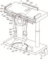
Fig. 1 is a schematic perspective view of the present invention;
fig. 2 is a schematic structural view of the rotating mechanism, the fastening mechanism and the angle adjusting mechanism of the present invention;
FIG. 3 is an enlarged schematic view of the structure at the position A of the present invention;
fig. 4 is a cross-sectional view of the present invention;
1. a main body plate; 2. a rotating mechanism; 201. a bearing; 202. a rotating plate; 203. a gear ring; 204. a motor gear; 205. a first motor; 3. a first electric telescopic rod; 4. a support pillar; 5. placing the plate; 6. a fastening mechanism; 601. a screw; 602. a first telescopic rod; 603. a spring; 604. a second positioning plate; 605. a damper plate; 606. a bevel gear; 607. a second motor; 608. a motor bevel gear; 7. a power switch group; 8. an angle adjusting mechanism; 801. a positioning frame; 802. a first connecting shaft; 803. a first movable block; 804. a second electric telescopic rod; 805. a second connecting shaft; 806. a second movable block; 807. a moving block; 808. a pushing frame; 9. a second telescopic rod; 10. a universal wheel; 11. a first positioning plate; 12. a rotating ring; 13. a first rotating frame; 14. a first rotating lever; 15. a second rotating lever; 16. and a second rotating frame.
Detailed Description
The invention will be explained in more detail by the following examples, which disclose the invention and are intended to protect all technical improvements within the scope of the invention.
The plate supporting device for processing the firework outer barrel mold comprises a main body plate 1, wherein a rotating groove is formed in the main body plate 1, a rotating mechanism 2 is installed in the rotating groove, the position of the firework outer barrel mold is adjusted through the rotating mechanism 2, three first electric telescopic rods 3 are fixedly connected to the rotating end of the rotating mechanism 2, the three first electric telescopic rods 3 are separated by 120 degrees, a first positioning plate 11 is fixedly connected to the telescopic end of each first electric telescopic rod 3, a supporting column 4 is fixedly connected to each first positioning plate 11, an angle adjusting mechanism 8 is installed on each supporting column 4, a placing plate 5 is installed on the adjusting end of each angle adjusting mechanism 8, a second rotating frame 16 is fixedly connected to the top end of each supporting column 4, and a second rotating rod 15 is rotatably connected to each second rotating frame 16, the position of the second rotating rod 15 corresponds to the position of the placing plate 5 and is fixedly connected with the position of the placing plate, the height of the placing plate 5 is controlled by the first electric telescopic rod 3, four moving grooves are arranged on the placing plate 5, the four moving grooves are separated by 90 degrees, a fastening mechanism 6 is arranged in the moving grooves, the driving end of the fastening mechanism 6 is positioned on the second rotating rod 15, the fastening end of the fastening mechanism 6 is positioned on the upper surface of the placing plate 5 and is in sliding connection with the upper surface of the placing plate 5, four displacement grooves are arranged on the placing plate 5, the positions of the displacement grooves correspond to the positions of the moving grooves and are communicated with the moving grooves, a firework outer cylinder mold is placed by the placing plate 5, the firework outer cylinder mold is locked by the fastening mechanism 6 on the placing plate 5, a power switch group 7 is fixedly connected on the placing plate 5, and the input end of, the output end of the power switch group 7 is electrically connected with the input ends of the rotating mechanism 2, the fastening mechanism 6 and the angle adjusting mechanism 8, and the power switch group 7 is provided with switch buttons which are in one-to-one correspondence with the rotating mechanism 2, the fastening mechanism 6 and the angle adjusting mechanism 8.
The fastening mechanism 6 comprises a screw 601 and a second motor 607, the screw 601 is located in a moving groove on the placing plate 5 and is rotatably connected, one end of the screw 601 penetrates through the placing plate 5 to be connected with a bevel gear 606, a second positioning plate 604 is in threaded connection with the screw 601, a groove is formed in the second positioning plate 604, a first telescopic rod 602 and a spring 603 which are arranged at equal intervals are fixedly connected in the groove, the position of the first telescopic rod 602 corresponds to the position of the spring 603 and is sleeved, a damping plate 605 is fixedly connected to the telescopic ends of the first telescopic rod 602 and the spring 603, the second motor 607 is located on the second rotating rod 15 and is fixedly connected, the second motor 607 is connected with a motor bevel gear 608 through an output shaft, and the position of the motor bevel gear 608 corresponds to the position of the bevel gear 606 and is meshed with the same.
The angle adjusting mechanism 8 comprises four positioning frames 801 and pushing frames 808, the number of the positioning frames 801 is four, the four positioning frames 801 are separated by 90 degrees, the positioning frames 801 are located on the supporting columns 4 and fixedly connected, the positioning frames 801 are connected with first movable blocks 803 through first connecting shafts 802, the first movable blocks 803 are fixedly connected with second electric telescopic rods 804, the number of the pushing frames 808 is four, the four pushing frames 808 are separated by 90 degrees, the pushing frames 808 are located on the placing plates 5 and fixedly connected, the pushing frames 808 are internally and slidably connected with moving blocks 807, the moving blocks 807 are provided with moving grooves, the moving grooves are connected with second movable blocks 806 through second connecting shafts 805, and the positions of the second movable blocks 806 correspond to the positions of the telescopic ends of the second electric telescopic rods 804 and are fixedly connected.
The main part board 1 is fixedly connected with four second telescopic rods 9, the four second telescopic rods 9 are separated by 90 degrees, a first rotating frame 13 is fixedly connected to the telescopic end of each second telescopic rod 9, a first rotating rod 14 is rotatably connected to the first rotating frame 13, the top end of the first rotating rod 14 is fixedly connected with a rotating ring 12, and the rotating ring 12 is rotatably connected with the placing board 5.
The four corners of the placing plate 5 are supported by the second telescopic rods 9.
The four corners of the lower surface of the main body plate 1 are respectively fixedly connected with universal wheels 10.
When the plate supporting device for processing the firework outer barrel mold is used, a worker places the firework outer barrel mold on the placing plate 5, the second motor 607 drives the screw 601 to rotate through the motor bevel gear 608 and the bevel gear 606, the screw 601 drives the second positioning plate 604 to move, the firework outer barrel mold on the placing plate 5 is locked through the second positioning plate 604, the pressure is reduced through the damping plate 605 on the second positioning plate 604, the damage to the surface of the firework outer barrel mold caused by the second positioning plate 604 is avoided, the height of the placing plate 5 is adjusted through the first electric telescopic rod 3, the device is suitable for workers with different heights, the first motor 205 drives the placing plate 5 to rotate through the motor gear 204 and the gear ring 203, the worker can conveniently adjust the position of the firework outer barrel mold, the worker is prevented from walking back and forth, the moving block 807 is driven to move through the extension of the second electric telescopic rod 804, through the angle of placing board 5 of movable block 807 control, make things convenient for the staff to look over and install spare part to each angle of fireworks urceolus mould.
The invention is not described in detail in the prior art, and although the invention has been specifically shown and described in connection with the preferred embodiments, the method and the way of implementing the technical solution are numerous, and only the preferred embodiments of the invention have been described above, it should be understood by those skilled in the art that various changes in form and details may be made therein without departing from the spirit and scope of the invention as defined in the appended claims, which are within the scope of the invention.
Claims (6)
1. The utility model provides a panel strutting arrangement of fireworks urceolus mould processing usefulness, includes main part board (1), characterized by: the novel electric heating plate is characterized in that a rotating groove is formed in the main body plate (1), a rotating mechanism (2) is installed in the rotating groove, three first electric telescopic rods (3) are fixedly connected to the rotating end of the rotating mechanism (2), the three first electric telescopic rods (3) are separated by 120 degrees, a first positioning plate (11) is fixedly connected to the telescopic end of each first electric telescopic rod (3), a supporting column (4) is fixedly connected to the first positioning plate (11), an angle adjusting mechanism (8) is installed on each supporting column (4), a placing plate (5) is installed at the adjusting end of each angle adjusting mechanism (8), a second rotating frame (16) is fixedly connected to the top end of each supporting column (4), a second rotating rod (15) is rotatably connected to the second rotating frame (16), and the position of the second rotating rod (15) corresponds to the position of the placing plate (5) and is fixedly connected to the position of the placing plate, the utility model discloses a novel electric power switch, including place board (5), be equipped with four shifting chutes on place board (5), be separated by 90 between four shifting chutes, install fastening device (6) in the shifting chute, the drive end of fastening device (6) is located second dwang (15), the fastening end of fastening device (6) is located the upper surface and the sliding connection of placing board (5), be equipped with four shifting chutes on placing board (5), the position of shifting chute is corresponding and the intercommunication with the position of shifting chute, fixedly connected with switch group (7) on placing board (5), the input of switch group (7) is connected with external power source's output, the output of switch group (7) is connected with slewing mechanism (2), fastening device (6) and angle adjustment mechanism's (8) input electricity.
2. The plate supporting device for the outer cylinder die processing of fireworks according to claim 1, characterized in that: slewing mechanism (2) are including bearing (201) and first motor (205), rotation inslot and fixed connection that bearing (201) are located on main part board (1), fixedly connected with rotor plate (202) are served in the rotation of bearing (201), first electric telescopic handle (3) and gear circle (203) of fixedly connected with on rotor plate (202), first electric telescopic handle (3) are located gear circle (203), first motor (205) are located on main part board (1) and fixed connection, first motor (205) are connected with motor gear (204) through the motor shaft, the position of motor gear (204) and the corresponding and meshing connection in position of gear circle (203).
3. The plate supporting device for the outer cylinder die processing of fireworks according to claim 1, characterized in that: the fastening mechanism (6) comprises a screw rod (601) and a second motor (607), the screw rod (601) is positioned in a moving groove on the placing plate (5) and is rotationally connected, one end of the screw rod (601) penetrates through the placing plate (5) to be connected with a bevel gear (606), a second positioning plate (604) is in threaded connection with the screw rod (601), a groove is arranged on the second positioning plate (604), a first telescopic rod (602) and a spring (603) which are arranged at equal intervals are fixedly connected in the groove, the position of the first telescopic rod (602) corresponds to the position of the spring (603) and is sleeved, a damping plate (605) is fixedly connected with the telescopic ends of the first telescopic rod (602) and the spring (603), the second motor (607) is positioned on a second rotating rod (15) and is fixedly connected, and is connected with a motor bevel gear (608) through an output shaft, the position of the motor bevel gear (608) corresponds to the position of the bevel gear (606) and is in meshed connection with the bevel gear.
4. The plate supporting device for the outer cylinder die processing of fireworks according to claim 1, characterized in that: the angle adjusting mechanism (8) comprises positioning frames (801) and pushing frames (808), the number of the positioning frames (801) is four, the four positioning frames (801) are separated by 90 degrees, the positioning frames (801) are located on the supporting columns (4) and fixedly connected, the positioning frames (801) are connected with first movable blocks (803) through first connecting shafts (802), the first movable blocks (803) are fixedly connected with second electric telescopic rods (804), the pushing frames (808) are four in number, the four pushing frames (808) are separated by 90 degrees, the pushing frames (808) are located on the placing plates (5) and fixedly connected, the pushing frames (808) are connected with movable blocks (807) in a sliding mode, the movable blocks (807) are provided with movable grooves, the movable grooves are connected with second movable blocks (806) through second connecting shafts (805), and the positions of the second movable blocks (806) correspond to the positions of the telescopic ends of the second electric telescopic rods (804) and are fixed And (4) fixing connection.
5. The plate supporting device for the outer cylinder die processing of fireworks according to claim 1, characterized in that: the utility model discloses a portable multifunctional electric scooter, including main part board (1), four second telescopic links (9) of fixedly connected with are gone up to main part board (1), are separated by 90 between four second telescopic links (9), the flexible first rotating turret (13) of fixedly connected with that serves of second telescopic link (9), first rotating turret (13) internal rotation is connected with first pivot pole (14), the top and the rotating ring (12) fixed connection of first pivot pole (14), rotating ring (12) with place board (5) and rotate and be connected.
6. The plate supporting device for the outer cylinder die processing of fireworks according to claim 1, characterized in that: the four corners of the lower surface of the main body plate (1) are respectively and fixedly connected with universal wheels (10).
Priority Applications (1)
| Application Number | Priority Date | Filing Date | Title |
|---|---|---|---|
| CN202021674740.0U CN213197176U (en) | 2020-08-13 | 2020-08-13 | Panel strutting arrangement of fireworks urceolus mould processing usefulness |
Applications Claiming Priority (1)
| Application Number | Priority Date | Filing Date | Title |
|---|---|---|---|
| CN202021674740.0U CN213197176U (en) | 2020-08-13 | 2020-08-13 | Panel strutting arrangement of fireworks urceolus mould processing usefulness |
Publications (1)
| Publication Number | Publication Date |
|---|---|
| CN213197176U true CN213197176U (en) | 2021-05-14 |
Family
ID=75838662
Family Applications (1)
| Application Number | Title | Priority Date | Filing Date |
|---|---|---|---|
| CN202021674740.0U Expired - Fee Related CN213197176U (en) | 2020-08-13 | 2020-08-13 | Panel strutting arrangement of fireworks urceolus mould processing usefulness |
Country Status (1)
| Country | Link |
|---|---|
| CN (1) | CN213197176U (en) |
-
2020
- 2020-08-13 CN CN202021674740.0U patent/CN213197176U/en not_active Expired - Fee Related
Similar Documents
| Publication | Publication Date | Title |
|---|---|---|
| CN108748082B (en) | Chassis moving mechanism of robot | |
| CN211806125U (en) | A manipulator structure of an industrial robot | |
| CN202574633U (en) | Large high-precision large-inertia rotating and assembling mechanical arm system | |
| CN202726912U (en) | Loading/unloading servo simulation manipulator | |
| CN211177899U (en) | Energy-saving type super-energy cement rotary kiln | |
| CN213802669U (en) | A hoisting mechanism for the installation of mine electromechanical equipment | |
| CN220580445U (en) | Trowelling machine | |
| CN219535409U (en) | Auxiliary device for installation of power distribution cabinet | |
| CN218927801U (en) | Industrial robot | |
| CN115180378B (en) | Automatic overturning method for round part | |
| CN219812100U (en) | Follow-up solar charging panel and support for motor home | |
| CN216795387U (en) | High-precision full-automatic chip mounter | |
| CN213452675U (en) | Improved generation industrial robot is with installation base convenient to adjust | |
| CN214899601U (en) | Over-and-under type block terminal | |
| CN107769707A (en) | A kind of solar-cell panel support of installation easy to disassemble | |
| CN220223364U (en) | Device for adjusting angle of electric hoist | |
| CN223719231U (en) | Shaping equipment for machining automotive suspension | |
| CN218570041U (en) | Motor controller convenient to installation is dismantled | |
| CN222135030U (en) | A robot base capable of compensating height | |
| CN220873146U (en) | Multi-functional real equipment of instructing of robot | |
| CN220580452U (en) | Steel structure bracket | |
| CN221913888U (en) | Rack convenient to tablet sculpture | |
| CN221424747U (en) | Environment-friendly scientific and technological lighting device convenient to remove | |
| CN118492785B (en) | All-position trackless crawling welding robot and application method thereof | |
| CN221439659U (en) | A piece rack for toughened glass production line |
Legal Events
| Date | Code | Title | Description |
|---|---|---|---|
| GR01 | Patent grant | ||
| GR01 | Patent grant | ||
| CF01 | Termination of patent right due to non-payment of annual fee | ||
| CF01 | Termination of patent right due to non-payment of annual fee |
Granted publication date: 20210514 |