Cleaning device for bridge pavement
Technical Field
The utility model relates to a bridge road surface technical field specifically is a cleaning device is used on bridge road surface.
Background
Along with the continuous change and development of traffic construction, new standards and requirements are provided for road and bridge junction planning, and in a certain sense, the rationality of road and bridge planning is not only related to the safety problem, but also highly attaches importance to the sanitation treatment of bridges.
In current bridge road surface cleaning device, current cleaning device can't clear up ya zi to the road surface, and general cleaning device can only carry out the large tracts of land clearance to neglected the detail processing on the road edgewise, reduced cleaning efficiency, and general cleaning device is not convenient for dismantle the installation to the broom, leads to in time changing and wasing.
SUMMERY OF THE UTILITY MODEL
An object of the utility model is to provide a cleaning device for bridge road surface to solve above-mentioned background art and propose in current bridge road surface cleaning device, current cleaning device can't clear up the pavement ya zi, general cleaning device can only carry out the large tracts of land to flat road surface and clear up, thereby neglected the detail processing on the road edgewise, reduce cleaning efficiency, and general cleaning device is not convenient for dismantle the installation to the broom, lead to can't in time change and abluent problem.
In order to achieve the above object, the utility model provides a following technical scheme: a cleaning device for a bridge pavement comprises a handle, a first knob, a support frame, a connecting rod, a bevel gear and a connecting plate, wherein a box body is connected to the right side of the handle, universal wheels are arranged below the box body, a water inlet is arranged above the box body, a water collecting tank is connected below the water inlet, a spray head is arranged below the water collecting tank, the first knob is located at the center position above the box body, a first rotating shaft is connected below the first knob, a first rotating wheel is connected below the first rotating shaft, a clamping groove is arranged below the first rotating wheel and is clamped with a buckle, the buckle is connected with a first broom, the support frame is located on the right side of the box body, a rotating handle is arranged on the surface of the right side of the support frame and is connected with a second rotating shaft, and a rotating gear is arranged at the tail end of the second rotating shaft, the connecting rod is connected with the rotating gear in a meshed mode, a supporting rod is arranged at one end of the connecting rod, a sliding groove is formed in the surface of the connecting rod, the sliding groove is connected with a pulley in a sliding mode, the connecting block is provided with a second rotating wheel, an eccentric wheel is arranged on the second rotating wheel, the connecting plate is fixedly connected with the second rotating wheel, the connecting groove and the connecting groove are clamped mutually, a second broom is installed on the surface of the connecting plate in a fixed mode, the bevel gear is connected with the eccentric wheel, and a second knob is arranged above the bevel gear.
Preferably, the first rotating shaft is connected with the first broom through the clamping groove and the buckle in a clamping manner, and the first broom and the box body form a rotating structure through the first rotating shaft.
Preferably, the connecting rods are distributed up and down relative to the rotating gear, one end of each connecting rod is in a conical sawtooth shape, and the connecting rods and the second broom form a telescopic structure through the rotating gear.
Preferably, the connecting blocks are symmetrically distributed about the connecting rod, and the pulleys form a sliding structure through the connecting blocks and the sliding grooves.
Preferably, the second rotating wheel is connected with the second broom in a clamping manner through a connecting plate and a connecting groove, and the second broom is symmetrically distributed relative to the supporting frame.
Preferably, the bevel gear is meshed and connected, and the second broom and the support frame form a rotating structure through the bevel gear.
Compared with the prior art, the beneficial effects of the utility model are that: a cleaning device for bridge pavement;
(1) the first broom can be driven by the first rotating shaft to conveniently clean a road surface in a large range, and the connecting rod can conveniently rotate the second broom by the rotating gear, so that the second broom can conveniently clean the edge of the road, and the cleaning efficiency is improved;
(2) it is convenient that connecting block and second rotate the wheel through pulley and spout and rotate to the convenience rotates the second broom, conveniently installs and dismantles the second broom through spread groove and connecting plate, is favorable to carrying out timely change and washing to the second broom, conveniently drives the second through conical gear and rotates the wheel and rotate.
Drawings
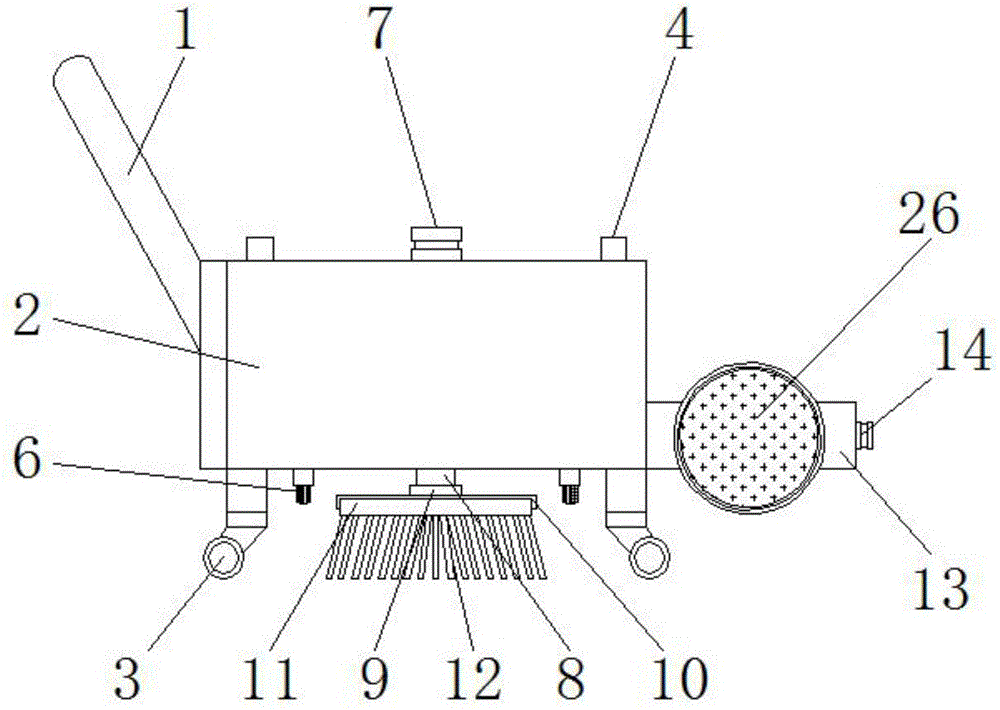
FIG. 1 is a schematic front view of the present invention;
FIG. 2 is a schematic view of the front internal structure of the present invention;
FIG. 3 is a schematic side view of the present invention;
fig. 4 is an enlarged schematic structural view of a portion a in fig. 3 according to the present invention.
In the figure: 1. a handle; 2. a box body; 3. a universal wheel; 4. a water inlet; 5. a water collection tank; 6. a spray head; 7. a first knob; 8. a first rotating shaft; 9. a first rotating wheel; 10. a card slot; 11. buckling; 12. A first broom; 13. a support frame; 14. rotating the handle; 15. a second rotation shaft; 16. a rotating gear; 17. a connecting rod; 18. a support bar; 19. a chute; 20. a pulley; 21. connecting blocks; 22. a second rotating wheel; 23. an eccentric wheel; 24. connecting grooves; 25. a connecting plate; 26. a second broom; 27. a bevel gear; 28. a second knob.
Detailed Description
The technical solutions in the embodiments of the present invention will be described clearly and completely with reference to the accompanying drawings in the embodiments of the present invention, and it is obvious that the described embodiments are only some embodiments of the present invention, not all embodiments. Based on the embodiments in the present invention, all other embodiments obtained by a person skilled in the art without creative work belong to the protection scope of the present invention.
Referring to fig. 1-4, the present invention provides a technical solution: a cleaning device for bridge pavement comprises a handle 1, a first knob 7, a support frame 13, a connecting rod 17, a bevel gear 27 and a connecting groove 24, wherein the right side of the handle 1 is connected with a box body 2, a universal wheel 3 is arranged below the box body 2, a water inlet 4 is arranged above the box body 2, a water collecting box 5 is connected below the water inlet 4, a spray head 6 is arranged below the water collecting box 5, the first knob 7 is positioned at the upper center of the box body 2, a first rotating shaft 8 is connected below the first knob 7, a first rotating wheel 9 is connected below the first rotating shaft 8, a clamping groove 10 is arranged below the first rotating wheel 9, the clamping groove 10 and the clamping buckle 11 are mutually clamped, the clamping buckle 11 is connected with a first broom 12, the support frame 13 is positioned at the right side of the box body 2, a rotating handle 14 is arranged on the right side surface of the support frame 13, and the rotating handle 14 is connected with a second rotating shaft 15, meanwhile, a rotating gear 16 is arranged at the tail end of the second rotating shaft 15, a connecting rod 17 is meshed with the rotating gear 16, a supporting rod 18 is arranged at one end of the connecting rod 17, a sliding groove 19 is formed in the surface of the connecting rod 17, the sliding groove 19 is connected with a pulley 20 in a sliding manner, the pulley 20 is connected with a connecting block 21, the connecting block 21 is provided with a second rotating wheel 22, an eccentric wheel 23 is arranged on the second rotating wheel 22, a connecting groove 24 is fixedly connected with the second rotating wheel 22, the connecting groove 24 is clamped with a connecting plate 25, a second broom 26 is fixedly arranged on the surface of the connecting plate 25, a conical gear 27 is connected with the eccentric wheel 23, and a second knob 28 is arranged above the.
The first rotating shaft 8 is connected with the first broom 12 through the clamping groove 10 and the buckle 11 in a clamping manner, the first broom 12 forms a rotating structure with the box body 2 through the first rotating shaft 8, and the first broom 12 can be driven by the first rotating shaft 8 to conveniently clean the road surface on a large scale.
The connecting rod 17 distributes about the rotary gear 16 from top to bottom, and the one end of connecting rod 17 is the toper cockscomb structure to connecting rod 17 constitutes extending structure through rotary gear 16 and second broom 26, and connecting rod 17 conveniently rotates second broom 26 through rotary gear 16, thereby makes second broom 26 conveniently clear up the road edgewise, thereby improves cleaning efficiency.
The connecting blocks 21 are symmetrically distributed about the connecting rod 17, and the pulleys 20 form a sliding structure with the sliding grooves 19 through the connecting blocks 21, and it is convenient for the connecting blocks 21 and the second rotating wheel 22 to rotate through the pulleys 20 and the sliding grooves 19, so that the second broom 26 is conveniently rotated.
The second rotating wheel 22 is connected with the second broom 26 through the connecting plate 25 and the connecting groove 24 in a clamping manner, the second broom 26 is symmetrically distributed about the supporting frame 13, and the second broom 26 is conveniently mounted and dismounted through the connecting groove 24 and the connecting plate 25, so that the second broom 26 can be replaced and cleaned in time.
The bevel gear 27 is engaged, and the second broom 26 forms a rotating structure with the supporting frame 13 through the bevel gear 27, and the second rotating wheel 22 is conveniently driven to rotate through the bevel gear 27.
The working principle is as follows: firstly, as shown in fig. 1-4, the external water pipe is connected with the water inlet 4, water is filled into the water collecting tank 5 through the water inlet 4, after the water is filled, the handle 1 is pushed to move the tank body 2 to the road surface through the universal wheel 3, then the first knob 7 is rotated to rotate the connected first rotating shaft 8, the first rotating shaft 8 rotates to drive the first rotating wheel 9 to rotate, because the first broom 12 is connected with the first rotating wheel 9 in a clamping way through the clamping groove 10 and the clamping buckle 11 in a clamping way, the connected first broom 12 rotates through the first rotating wheel 9 to clean the road surface, meanwhile, the spray head 6 sprays water to the road surface, when the road edge of the road surface needs to be cleaned, the rotating handle 14 is rotated to drive the second rotating shaft 15 to rotate, the second rotating shaft 15 rotates to drive the connected rotating gear 16 to rotate, the rotating gear 16 is meshed with the connecting rod 17, the rotating gear 16 rotates to drive the connecting rods 17 at the upper and lower positions to move outwards and extend, so that the second broom 26 extends outwards, then the second knob 28 is rotated to drive the bevel gear 27 to rotate, the bevel gear 27 rotates to drive the connected eccentric wheel 23 to rotate, the eccentric wheel 23 rotates to drive the second rotating wheel 22 to rotate, meanwhile, the second rotating wheel 22 rotates to drive the connected second broom 26 to rotate so as to clean the road edge, when the second broom 26 needs to be disassembled, the connecting plate 25 is separated from the connecting groove 24, and therefore the bridge road cleaning device is used by people, and the bridge road cleaning device is used in the bridge road cleaning process.
Although the present invention has been described in detail with reference to the foregoing embodiments, it will be apparent to those skilled in the art that modifications may be made to the embodiments or portions thereof without departing from the spirit and scope of the invention.