CN213173109U - Automatic cutting device of filter bag - Google Patents
Automatic cutting device of filter bag Download PDFInfo
- Publication number
- CN213173109U CN213173109U CN202021199028.XU CN202021199028U CN213173109U CN 213173109 U CN213173109 U CN 213173109U CN 202021199028 U CN202021199028 U CN 202021199028U CN 213173109 U CN213173109 U CN 213173109U
- Authority
- CN
- China
- Prior art keywords
- filter bag
- plate
- cutting device
- fixed
- cut
- Prior art date
- Legal status (The legal status is an assumption and is not a legal conclusion. Google has not performed a legal analysis and makes no representation as to the accuracy of the status listed.)
- Expired - Fee Related
Links
- 238000005520 cutting process Methods 0.000 title claims abstract description 36
- 238000003825 pressing Methods 0.000 claims description 7
- 239000004744 fabric Substances 0.000 abstract description 23
- 238000000034 method Methods 0.000 abstract description 7
- XEEYBQQBJWHFJM-UHFFFAOYSA-N Iron Chemical compound [Fe] XEEYBQQBJWHFJM-UHFFFAOYSA-N 0.000 abstract description 4
- 230000002349 favourable effect Effects 0.000 abstract description 3
- 229910052742 iron Inorganic materials 0.000 abstract description 2
- 238000005457 optimization Methods 0.000 description 5
- 230000006835 compression Effects 0.000 description 3
- 238000007906 compression Methods 0.000 description 3
- 238000007599 discharging Methods 0.000 description 1
- 230000000694 effects Effects 0.000 description 1
- 239000000463 material Substances 0.000 description 1
- 238000012986 modification Methods 0.000 description 1
- 230000004048 modification Effects 0.000 description 1
- 238000009958 sewing Methods 0.000 description 1
- 238000003860 storage Methods 0.000 description 1
Images

Landscapes
- Treatment Of Fiber Materials (AREA)
Abstract
The utility model relates to a cutting device technical field, specific cross automatic cutting device of filter bag that says so, which comprises a worktable, the middle part of board is fixed with the support, install the cylinder on the support, the fixed plate is installed to the output of cylinder, the lower surface of fixed plate is installed through the blade holder and is cut the sword, there is the clamp plate fixed plate on the left of the fixed plate through the depression bar connection, and the board fixed surface that is located and cuts the sword below has and cuts the seat, it is provided with steam chamber and sword groove in the seat to cut, the board surface still is provided with the silo, slidable mounting has the locating. The utility model discloses a rotating the stay bolt and carrying out the push-and-pull to the locating plate, can adjusting the excision width, utilize the spring to promote the clamp plate and compress tightly fixedly to filter bag cloth one side, prevent to cut in-process cloth and remove, improve and cut the quality, iron the part that compresses tightly through steam interface spun high temperature steam simultaneously for filter bag cloth edge is neat, is favorable to the follow-up processing of making up.
Description
Technical Field
The utility model belongs to the technical field of cutting device, concretely relates to cross automatic cutting device of filter bag.
Background
When the filter bag is processed, because certain deckle edge, turn-up phenomenon can take place for the filter bag cloth in storage, removal process, need cut the edge of filter bag cloth in advance, get rid of deckle edge, the turn-up part at filter bag cloth edge to follow-up processing of making up is convenient for. At present, when cutting the filter bag cloth, current equipment can't carry out the flattening to cutting the position and handle, and the unevenness's phenomenon appears easily in the filter bag cloth after cutting, is unfavorable for follow-up processing of making up.
SUMMERY OF THE UTILITY MODEL
An object of the utility model is to provide a cross automatic cutting device of filter bag to solve the problem that proposes in the above-mentioned background art.
In order to achieve the above object, the utility model provides a following technical scheme: the utility model provides a cross automatic cutting device of filter bag, includes the board, the middle part of board is fixed with the support, install the cylinder on the support, the fixed plate is installed to the output of cylinder, the lower surface of fixed plate is installed through the blade holder and is cut the sword, there is the clamp plate fixed surface that is located and cuts the sword below through compression linkage in the fixed plate left side, be provided with steam chamber and sword groove in cutting the seat, the board surface still is provided with the charging chute, slidable mounting has the locating plate in the charging chute.
As a further optimization of the technical scheme, guide rods are further fixed at two ends of the upper surface of the fixing plate and movably penetrate through the bracket.
As a further optimization of the technical scheme, the compression bar is provided with two ends which are respectively movably arranged on the fixed plate, and the compression bar is sleeved with a spring.
As a further optimization of the technical scheme, the pressing plate is arranged opposite to the steam cavity.
As a further optimization of the technical scheme, the upper surface of the steam cavity is uniformly distributed with air holes, and one end of the steam cavity is provided with a steam interface.
As a further optimization of the technical scheme, guide rails are respectively fixed on two sides in the charging chute, the side edges of the positioning plates are installed on the guide rails, the positioning plates are further rotatably provided with long bolts, and the long bolts are installed at one end of the charging chute.
The utility model discloses a technological effect and advantage:
the utility model discloses a rotating the stay bolt and carrying out the push-and-pull to the locating plate, can adjusting the excision width, utilize the spring to promote the clamp plate and compress tightly fixedly to filter bag cloth one side, prevent to cut in-process cloth and remove, improve and cut the quality, iron the part that compresses tightly through steam interface spun high temperature steam simultaneously for filter bag cloth edge is neat, is favorable to the follow-up processing of making up.
Drawings
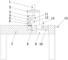
Fig. 1 is a schematic structural view of the present invention;
FIG. 2 is a schematic view of the mounting structure of the bracket and the fixing plate of the present invention;
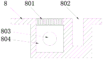
fig. 3 is a schematic view of the cutting seat structure of the present invention.
In the figure: 1. a cylinder; 2. a support; 3. a fixing plate; 4. a spring; 5. a pressure lever; 6. pressing a plate; 7. a machine platform; 8. a cutting seat; 801. air holes; 802. a cutter groove; 803. a steam interface; 804. a steam chamber; 9. a charging chute; 10. a guide rail; 11. a tool apron; 12. cutting knife; 13. positioning a plate; 14. a long bolt; 15. a guide rod.
Detailed Description
The technical solutions in the embodiments of the present invention will be described clearly and completely below with reference to the embodiments of the present invention, and it is obvious that the described embodiments are only some embodiments of the present invention, not all embodiments. Based on the embodiments in the present invention, all other embodiments obtained by a person skilled in the art without creative work belong to the protection scope of the present invention.
As shown in fig. 1-3, an automatic cutting device for filter bags comprises a machine table 7, wherein a support 2 is fixed in the middle of the machine table 7, an air cylinder 1 is installed on the support 2, a fixing plate 3 is installed at the output end of the air cylinder 1, guide rods 15 are further fixed at two ends of the upper surface of the fixing plate 3, and the guide rods 15 movably penetrate through the support 2. Under the drive of cylinder 1, can lead fixed plate 3 through guide arm 15 for fixed plate 3 reciprocates the in-process and prevents to deflect, improves fixed plate 3's stability.
The lower surface of fixed plate 3 installs through blade holder 11 and cuts sword 12, fixed plate 3 left side is connected with clamp plate 6 through depression bar 5, depression bar 5 is provided with two respectively movable mounting in the both ends of fixed plate 3, the cover is equipped with spring 4 on the depression bar 5, and during initial state, clamp plate 6 highly is less than and cuts sword 12, utilizes clamp plate 6, can compress tightly the filter bag cloth in advance when cutting sword 12 contact filter bag cloth, keeps the stability of filter bag cloth, prevents to cut the in-process and takes place the skew, guarantees to cut the precision.
The fixed surface of the machine table 7 below the cutting knife 12 is provided with a cutting seat 8, the upper surface of the cutting seat 8 is flush with the surface of the machine table 7, filter bag cloth can be pushed conveniently, a steam cavity 804 and a knife groove 802 are arranged in the cutting seat 8, air holes 801 are uniformly distributed in the upper surface of the steam cavity 804, one end of the steam cavity 804 is provided with a steam interface 803, the pressing plate 6 is arranged opposite to the steam cavity 804, a steam pipeline is connected with the steam interface 803, steam can be added into the steam cavity 804, and therefore the filter bag cloth is ironed by steam in the pressing plate 6 pressing process, cuts are tidy, and subsequent sewing processing of the filter bag cloth is facilitated.
The cutting machine is characterized in that a blanking groove 9 is further formed in the surface of the machine table 7, a positioning plate 13 is slidably mounted in the blanking groove 9, the blanking groove 9 is used for discharging cut leftover materials, guide rails 10 are respectively fixed to two sides in the blanking groove 9, the side edge of the positioning plate 13 is mounted on the guide rails 10, a long bolt 14 is further rotatably arranged on the positioning plate 13, the long bolt 14 is mounted at one end of the blanking groove 9, the positioning plate 13 can be pushed and pulled by rotating the long bolt 14, the positioning plate 13 can be moved left and right in the supporting and guiding mode of the guide rails 10, the distance between the positioning plate 13 and the cutting knife 12 is adjusted, and the.
Specifically, when in use, the positioning plate 13 is first adjusted according to the cutting width, and the long bolt 14 is rotated to push and pull the positioning plate 13, so that the distance between the positioning plate 13 and the cutting blade 12 and the cutting width are adjusted. When cutting the filter bag cloth, support the one end that the filter bag cloth needs the excision to fix a position on the surface of locating plate 13, start cylinder 1 and promote fixed plate 3 and move down, at first utilize spring 4 to promote clamp plate 6 and compress tightly fixedly filter bag cloth one side, prevent to cut in-process cloth and remove, improve and cut the quality, press the part through steam interface 803 spun high temperature steam to compressing tightly simultaneously, make filter bag cloth edge neat, be favorable to follow-up processing of making up, along with continuing of fixed plate 3 moves down, cut sword 12 and cut the filter bag cloth, after cutting, cylinder 1 drives fixed plate 3 and moves up, make clamp plate 6 and cut sword 12 reset, take out the part of accomplishing the cutting, leftover bits after cutting are discharged through chute 9.
Finally, it should be noted that: although the present invention has been described in detail with reference to the foregoing embodiments, it will be apparent to those skilled in the art that modifications and variations can be made in the embodiments or in part of the technical features of the embodiments without departing from the spirit and the scope of the invention.
Claims (6)
1. The utility model provides an automatic cutting device of filter bag, includes board (7), its characterized in that: the middle part of board (7) is fixed with support (2), install cylinder (1) on support (2), fixed plate (3) are installed to the output of cylinder (1), the lower surface of fixed plate (3) is installed through blade holder (11) and is cut sword (12), fixed plate (3) left side is connected with clamp plate (6) through depression bar (5), and board (7) fixed surface that is located and cuts sword (12) below is cut seat (8), it is provided with steam chamber (804) and sword groove (802) to cut seat (8), board (7) surface still is provided with silo (9), sliding mounting has locating plate (13) in silo (9).
2. An automatic filter bag cutting device as claimed in claim 1, wherein: guide rods (15) are further fixed to two ends of the upper surface of the fixing plate (3), and the guide rods (15) penetrate through the support (2) movably.
3. An automatic filter bag cutting device as claimed in claim 1, wherein: the pressing rod (5) is provided with two ends which are movably arranged on the fixing plate (3) respectively, and the pressing rod (5) is sleeved with a spring (4).
4. An automatic filter bag cutting device as claimed in claim 1, wherein: the pressure plate (6) is arranged opposite to the steam cavity (804).
5. An automatic filter bag cutting device as claimed in claim 4, wherein: air holes (801) are uniformly distributed on the upper surface of the steam cavity (804), and a steam interface (803) is arranged at one end of the steam cavity (804).
6. An automatic filter bag cutting device as claimed in claim 1, wherein: guide rails (10) are fixed on two sides in the charging chute (9) respectively, the side edges of the positioning plates (13) are installed on the guide rails (10), long bolts (14) are further rotatably arranged on the positioning plates (13), and the long bolts (14) are installed at one end of the charging chute (9).
Priority Applications (1)
| Application Number | Priority Date | Filing Date | Title |
|---|---|---|---|
| CN202021199028.XU CN213173109U (en) | 2020-06-24 | 2020-06-24 | Automatic cutting device of filter bag |
Applications Claiming Priority (1)
| Application Number | Priority Date | Filing Date | Title |
|---|---|---|---|
| CN202021199028.XU CN213173109U (en) | 2020-06-24 | 2020-06-24 | Automatic cutting device of filter bag |
Publications (1)
| Publication Number | Publication Date |
|---|---|
| CN213173109U true CN213173109U (en) | 2021-05-11 |
Family
ID=75791128
Family Applications (1)
| Application Number | Title | Priority Date | Filing Date |
|---|---|---|---|
| CN202021199028.XU Expired - Fee Related CN213173109U (en) | 2020-06-24 | 2020-06-24 | Automatic cutting device of filter bag |
Country Status (1)
| Country | Link |
|---|---|
| CN (1) | CN213173109U (en) |
Cited By (1)
| Publication number | Priority date | Publication date | Assignee | Title |
|---|---|---|---|---|
| CN113930928A (en) * | 2021-10-25 | 2022-01-14 | 绍兴绒之音针纺有限公司 | Polar fleece machine with cutting function |
-
2020
- 2020-06-24 CN CN202021199028.XU patent/CN213173109U/en not_active Expired - Fee Related
Cited By (2)
| Publication number | Priority date | Publication date | Assignee | Title |
|---|---|---|---|---|
| CN113930928A (en) * | 2021-10-25 | 2022-01-14 | 绍兴绒之音针纺有限公司 | Polar fleece machine with cutting function |
| CN113930928B (en) * | 2021-10-25 | 2024-02-06 | 绍兴绒之音针纺有限公司 | Shaking machine with cutting function |
Similar Documents
| Publication | Publication Date | Title |
|---|---|---|
| CN219403391U (en) | Aluminum product cutting equipment | |
| CN211993113U (en) | Automatic paper cutter | |
| CN113146743B (en) | Punching and cutting equipment for paperboard production | |
| CN220597967U (en) | Trimming device | |
| CN218192801U (en) | Plate shearing machine | |
| CN216359609U (en) | Intelligent paper cutting machine | |
| CN219191485U (en) | A flat mouth machine for plastic film composite bag processing | |
| CN215149469U (en) | A side cut device for paper production | |
| CN212199814U (en) | a cutting machine | |
| CN215471662U (en) | Robot base side cut shaping assembling die | |
| CN213114069U (en) | Sisal hemp surface fabric production is with cutting device | |
| CN214644089U (en) | Cutting device for printing | |
| CN211415270U (en) | A plastic belt waste material cutting and recycling device | |
| CN214529865U (en) | Electric cloth sample cutting machine | |
| CN221539992U (en) | Plastic tarpaulin processing equipment | |
| CN220477047U (en) | Leftover material cutting equipment for cloth cover rubber sole shoes | |
| CN218364962U (en) | Lace cutting device for edges of paper handbag | |
| CN223338464U (en) | Plate shearing machine | |
| CN221338702U (en) | Single-sided paper cutter | |
| CN222552302U (en) | A cutting device for piston rod production | |
| CN218699651U (en) | Environment-friendly cystosepiment cutting machine | |
| CN215545292U (en) | Steel sheet slicer that cutting accuracy is high | |
| CN220739596U (en) | Electrical control side cut device | |
| CN219793014U (en) | Automatic leather shaving machine | |
| CN219666864U (en) | Three-sided book trimming machine |
Legal Events
| Date | Code | Title | Description |
|---|---|---|---|
| GR01 | Patent grant | ||
| GR01 | Patent grant | ||
| CF01 | Termination of patent right due to non-payment of annual fee | ||
| CF01 | Termination of patent right due to non-payment of annual fee |
Granted publication date: 20210511 |