New forms of energy that easy to assemble fill electric pile
Technical Field
The utility model relates to a new forms of energy fill electric pile technical field specifically is an electric pile is filled to new forms of energy easy to assemble.
Background
The new energy is also called unconventional energy, refers to various energy forms except traditional energy, refers to energy which is just developed and utilized or is actively researched and is to be popularized, such as solar energy, geothermal energy, wind energy, ocean energy, biomass energy, nuclear fusion energy and the like, has the functions similar to those of an oiling machine in a gas station, can be fixed on the ground or on the wall, is installed in parking lots or charging stations of public buildings and residential districts, and can charge electric vehicles of various models according to different voltage grades
The novel energy charging pile convenient to mount is generally placed on the ground at present, collision can occur, accidents are caused, and therefore the novel energy charging pile convenient to mount is provided.
SUMMERY OF THE UTILITY MODEL
Technical problem to be solved
The utility model provides a not enough to prior art, the utility model provides an electric pile is filled to new forms of energy easy to assemble possesses and can removes the device on the vertical direction, can prevent some collisions, reduces advantages such as unexpected emergence, has solved and has generally put on the ground, and the collision can take place, leads to the problem of some unexpected emergence.
(II) technical scheme
In order to achieve the above object, the utility model provides a following technical scheme: the utility model provides an electric pile is filled to new forms of energy easy to assemble, includes the operation panel, the inside swing joint of operation panel has the threaded rod, threaded rod side surface threaded connection has the upper plate, the inside swing joint of upper plate has the pulling pole, pulling pole bottom fixedly connected with swash plate, roof fixedly connected with spring in the upper plate, threaded rod side surface threaded connection has the hypoplastron, hypoplastron top overlap joint has fills the electric pile body.
The right side of swash plate is for being the inclined plane, and the left side of swash plate is the vertically, and the main is can directly be blocked for the convenient electric pile body that fills.
Preferably, the top end of the threaded rod is fixedly connected with an upper gear, and the inside of the operating plate is movably connected with a shaft rod.
Preferably, the side surface of the shaft lever is fixedly connected with a lower gear, and the right end of the shaft lever is fixedly connected with a rotating wheel.
Preferably, the left side of the operation board is fixedly connected with a fixing board, the top of the operation board is fixedly connected with an anti-collision board, and the bottom of the anti-collision board is fixedly connected with a sponge block.
Preferably, fill electric pile body top left side and seted up the bevel connection, swash plate bottom and bevel connection looks adaptation.
Preferably, the bottom of the inclined plate penetrates through the upper plate and extends to the bottom of the upper plate, and the bottom of the spring is fixedly connected with the top of the inclined plate.
Compared with the prior art, the utility model provides an electric pile is filled to new forms of energy easy to assemble possesses following beneficial effect:
1. this electric pile is filled to new forms of energy easy to assemble, the threaded rod has been set up through the inside at the operation panel, side surface at the threaded rod has set up upper plate and hypoplastron, gear and lower gear have been set up in the bottom of threaded rod, upper gear and lower gear intermeshing, the inside axostylus axostyle right-hand member of lower gear has set up the runner, will fill electric pile body downstream when needs use, when not using, will fill electric pile body upstream, can prevent to fill electric pile body and receive the damage, prevent some unexpected emergence, protection device's effect has been reached.
2. This electric pile is filled to new forms of energy easy to assemble, through set up the pulling pole in the inside of upper plate, the swash plate has been set up in the bottom of pulling pole, the spring has been set up at the top of swash plate, the top and the upper plate inside roof fixed connection of spring, the top at filling the electric pile body has set up the bevel connection, bevel connection and swash plate looks adaptation, to fill electric pile body top in the installation there is bevel connection one side direct push to the operation panel, in the dismantlement, upwards stimulate the pulling pole and just can easily take out the electric pile body, high convenience and fastness, staff's installation rate has been improved, the effect of saving installation time has been reached.
Drawings
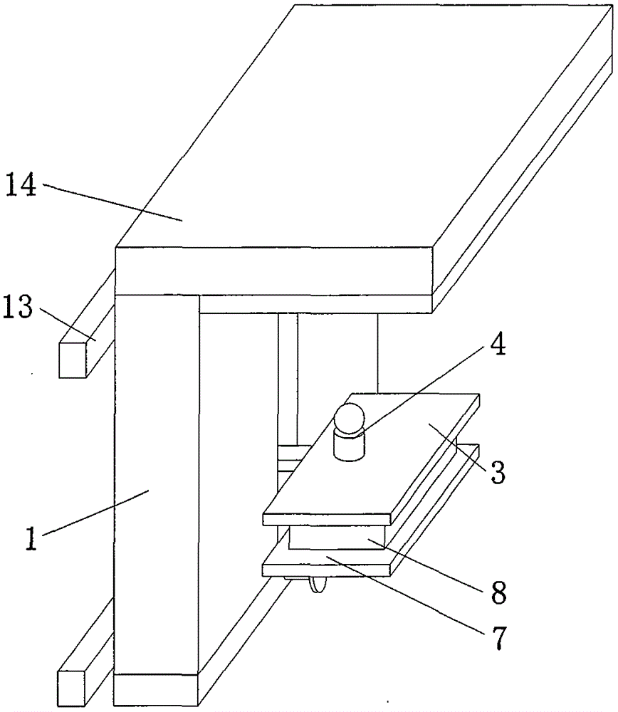
FIG. 1 is a perspective view of the present invention;
FIG. 2 is a schematic view of the internal structure of the operation panel of the present invention;
fig. 3 is an enlarged view of a structure in fig. 2 according to the present invention.
Wherein: 1. an operation panel; 2. a threaded rod; 3. an upper plate; 4. pulling a rod; 5. a sloping plate; 6. a spring; 7. a lower plate; 8. a charging pile body; 9. an upper gear; 10. a shaft lever; 11. a lower gear; 12. a rotating wheel; 13. a fixing plate; 14. an anti-collision plate; 15. a sponge block.
Detailed Description
The technical solutions in the embodiments of the present invention will be described clearly and completely with reference to the accompanying drawings in the embodiments of the present invention, and it is obvious that the described embodiments are only some embodiments of the present invention, not all embodiments. Based on the embodiments in the present invention, all other embodiments obtained by a person skilled in the art without creative work belong to the protection scope of the present invention.
Referring to fig. 1-3, a new forms of energy that facilitates installation fills electric pile includes operation panel 1, and the internal swing joint of operation panel 1 has threaded rod 2, and threaded rod 2 side surface threaded connection has upper plate 3, and the internal swing joint of upper plate 3 has pulling rod 4, and pulling rod 4 bottom fixedly connected with swash plate 5, and upper plate 3 inside roof fixedly connected with spring 6, threaded rod 2 side surface threaded connection has hypoplastron 7, and the overlap joint of hypoplastron 7 top has filled electric pile body 8.
Through the technical scheme, threaded rod 2 has been set up in the inside of operation panel 1, side surface at threaded rod 2 has set up upper plate 3 and hypoplastron 7, bottom at threaded rod 2 has set up gear 9 and lower gear 11, go up gear 9 and lower gear 11 intermeshing, the inside axostylus axostyle right-hand member of lower gear 11 has set up runner 12, will fill electric pile body 8 downstream when needs use, when not using, will fill electric pile body 8 rebound, can prevent to fill electric pile body 8 and receive the damage, prevent some unexpected emergence.
As shown in fig. 2, the top end of the threaded rod 2 is fixedly connected with an upper gear 9, and the inside of the operation plate 1 is movably connected with a shaft rod 10.
As shown in fig. 2, a lower gear 11 is fixedly connected to a side surface of the shaft 10, and a runner 12 is fixedly connected to a right end of the shaft 10.
By the above technical solution, the upper gear 9 and the lower gear 11 are simple devices for controlling the rotation of the threaded rod 2.
As shown in fig. 1, a fixing plate 13 is fixedly connected to the left side of the operation plate 1, an anti-collision plate 14 is fixedly connected to the top of the operation plate 1, and a sponge block 15 is fixedly connected to the bottom of the anti-collision plate 14.
Through above-mentioned technical scheme, the effect of sponge piece 15 is in order to prevent that the device from colliding at the in-process that rises, fills electric pile body 8 for the protection, and sponge piece 15 is protector, for current device.
As shown in fig. 3, the left side of the top of the charging pile body 8 is provided with an oblique opening, and the bottom of the inclined plate 5 is matched with the oblique opening.
Through the technical scheme, the right side of swash plate 5 is the inclined plane, the left side of swash plate 5 is the vertically, mainly be for conveniently filling electric pile body 8 and can directly be blocked, 3 inside pulling rods 4 that have set up in upper plate, the bottom of pulling rods 4 has set up swash plate 5, spring 6 has been set up at the top of swash plate 5, roof fixed connection in top and the upper plate 3 of spring 6, top filling electric pile body/has set up the bevel connection, bevel connection and 5 looks adaptations of swash plate, to fill electric pile body 8 top in the installation and have bevel connection one side direct push to operation panel 1, in the dismantlement, it just can easily take out to fill electric pile body 8 to pull rod 4 upwards, and is convenient and fast, and the installation speed of staff is improved.
As shown in fig. 3, the bottom of the inclined plate 5 penetrates through the upper plate 3 and extends to the bottom of the upper plate 3, and the bottom of the spring 6 is fixedly connected with the top of the inclined plate 5.
Through above-mentioned technical scheme, when the installation with dismantle and fill electric pile body 8, spring 6 is for resetting in order to make things convenient for control swash plate 5 can be fine.
When using, the staff fixes fixed plate 13 on the wall body, then will fill in the middle of electric pile body 8 puts into upper plate 3 and hypoplastron 7, at the in-process of putting into, make swash plate 5 insert in the bevel connection, when need not use, it makes threaded rod 2 drive and fills electric pile body 8 upward movement to rotate runner 12, when needs use, reverse rotation runner 12 makes threaded rod 2 drive and fills electric pile body 8 downstream, when electric pile body 8 is filled in needs dismantlement, 4 upwards stimulations will stimulate the pole in the pulling, make swash plate 5 break away from out from the bevel connection, then will fill electric pile body 8 take out can.
Although embodiments of the present invention have been shown and described, it will be appreciated by those skilled in the art that changes, modifications, substitutions and alterations can be made in these embodiments without departing from the principles and spirit of the invention, the scope of which is defined in the appended claims and their equivalents.