CN213160468U - Anchor type and spiral ribbon mixing and stirring device - Google Patents
Anchor type and spiral ribbon mixing and stirring device Download PDFInfo
- Publication number
- CN213160468U CN213160468U CN202021980120.XU CN202021980120U CN213160468U CN 213160468 U CN213160468 U CN 213160468U CN 202021980120 U CN202021980120 U CN 202021980120U CN 213160468 U CN213160468 U CN 213160468U
- Authority
- CN
- China
- Prior art keywords
- rotary drum
- wall
- device main
- fixedly connected
- main part
- Prior art date
- Legal status (The legal status is an assumption and is not a legal conclusion. Google has not performed a legal analysis and makes no representation as to the accuracy of the status listed.)
- Active
Links
- 238000003756 stirring Methods 0.000 title claims abstract description 46
- XLYOFNOQVPJJNP-UHFFFAOYSA-N water Substances O XLYOFNOQVPJJNP-UHFFFAOYSA-N 0.000 claims description 25
- 230000000149 penetrating effect Effects 0.000 claims 1
- 239000000463 material Substances 0.000 abstract description 25
- 230000000694 effects Effects 0.000 abstract description 4
- 239000007858 starting material Substances 0.000 abstract description 4
- 235000017166 Bambusa arundinacea Nutrition 0.000 description 15
- 235000017491 Bambusa tulda Nutrition 0.000 description 15
- 241001330002 Bambuseae Species 0.000 description 15
- 235000015334 Phyllostachys viridis Nutrition 0.000 description 15
- 239000011425 bamboo Substances 0.000 description 15
- 244000309464 bull Species 0.000 description 10
- 239000000203 mixture Substances 0.000 description 10
- 238000009434 installation Methods 0.000 description 5
- 238000004140 cleaning Methods 0.000 description 4
- 238000000034 method Methods 0.000 description 3
- 238000005457 optimization Methods 0.000 description 3
- 230000005540 biological transmission Effects 0.000 description 2
- 230000009286 beneficial effect Effects 0.000 description 1
- 238000007796 conventional method Methods 0.000 description 1
- 238000007599 discharging Methods 0.000 description 1
- 239000000284 extract Substances 0.000 description 1
- 239000012530 fluid Substances 0.000 description 1
- 238000012986 modification Methods 0.000 description 1
- 230000004048 modification Effects 0.000 description 1
- 239000000843 powder Substances 0.000 description 1
- 238000001556 precipitation Methods 0.000 description 1
- 239000002994 raw material Substances 0.000 description 1
- 238000007789 sealing Methods 0.000 description 1
- 239000013049 sediment Substances 0.000 description 1
- 238000000926 separation method Methods 0.000 description 1
- 239000000126 substance Substances 0.000 description 1
Images



Landscapes
- Mixers Of The Rotary Stirring Type (AREA)
Abstract
The utility model belongs to the technical field of mix agitating unit, especially, be an anchor formula and spiral shell area mix agitating unit, including the device main part, the right side wall fixedly connected with mounting panel of device main part, the up end of mounting panel can be dismantled and be connected with the motor, and the pivot outer wall cover of motor is equipped with the drive belt, and the opposite side cover of drive belt inner wall is equipped with the rotary drum, and the lower extreme of rotary drum runs through the device main part and extends to the inside of device main part. The cover is equipped with the bearing between rotary drum and the device main part, and the spiral shell area is installed to the outer wall of rotary drum, the three angular frame of lower extreme fixedly connected with of rotary drum, the lower extreme fixedly connected with scraper blade of three angular frame. During the material that will treat the stirring is put into the device main part, and starter motor passes through the drive belt and drives the rotary drum rotatory in the device main part, and then drives the spiral shell area and rotate and stir the material at middle part, and the material deposits downwards through the stirring, deposits and stirs at the three corner frames of material accessible and the scraper blade of device main part bottom, and then reaches the even effect of stirring.
Description
Technical Field
The utility model relates to a mix agitating unit technical field, concretely relates to anchor formula and spiral shell area mix agitating unit.
Background
To dry powder stirring operation in the chemical industry field, need to guarantee that the inside final stirring state of stirring barrel is even and stirring in-process stirring rake can drive the mixture and have good fluid form. The existing stirring paddle mostly adopts blade type or plate and frame type stirring paddle, the uniform stirring of the stirring center position, the bottom of the stirring paddle and the top of the stirring paddle in the mixing and stirring process cannot be ensured for the mixed material with larger viscosity, and the material is easy to accumulate at the bottom of the stirring cylinder after the final stirring; meanwhile, the helical ribbon type stirrer is inconvenient for workers to clean in the later period, and further the next material stirring operation is influenced.
Disclosure of Invention
For solving the problem that provides among the above-mentioned background art, the utility model provides an anchor formula and spiral shell area mix agitating unit can the internal material of co-mixing tank different height position, the staff of being convenient for simultaneously clears up the spiral shell area.
In order to achieve the above object, the utility model provides a following technical scheme: the utility model provides an anchor formula and spiral shell area mix agitating unit, includes the device main part, the right side wall fixedly connected with mounting panel of device main part, the up end of mounting panel can be dismantled and is connected with the motor, the pivot outer wall cover of motor is equipped with the drive belt, the opposite side cover of drive belt inner wall is equipped with the rotary drum, the lower extreme of rotary drum runs through the device main part and extends to the inside of device main part, the cover is equipped with the bearing between rotary drum and the device main part, the spiral shell area is installed to the outer wall of rotary drum, the three angle frames of lower extreme fixedly connected with of rotary drum, the lower extreme fixedly connected with.
In order to reach good cleaning performance to stirring spiral shell area, as the utility model relates to an anchor formula and spiral shell area mix agitating unit are preferred, the apopore has all been seted up to the left and right sides of rotary drum, the spacing section of thick bamboo of upper end fixedly connected with of rotary drum, first spacing groove has all been seted up to both sides around the spacing section of thick bamboo inner wall, the second spacing groove has all been seted up to the left and right sides of spacing section of thick bamboo inner wall, the inside through connection of rotary drum has the bull stick, the equal fixedly connected with connecting plate in the left and right sides of bull stick, two the equal fixedly connected with in one side and apopore assorted arc on the back of the connecting plate mutually, the upper end of bull stick runs through the rotary drum and extends to the top of rotary drum, the hollow section of thick bamboo of upper end fixedly connected with of bull stick, the equal fixedly connected with.
For convenient installation and dismantlement water pipe, as the utility model relates to an anchor formula and spiral shell area mixing stirring device are preferred, the outer wall of a spacing section of thick bamboo is rotated and is connected with installation head, the up end intercommunication of installation head has the water pipe.
For convenient device feeding and ejection of compact, conduct the utility model relates to an anchor formula and spiral shell area mixing stirring device are preferred, the left side wall intercommunication of device main part has the feeder hopper, the lower terminal surface intercommunication of device main part has the discharging pipe.
In order to further inject the position of bull stick, prevent that the bull stick from reciprocating as the utility model relates to an anchor formula and spiral shell area mix agitating unit is preferred, two the bottom in first spacing groove and two second spacing grooves is closed structure.
In order to further stabilize the position of fixed spiral shell area, as the utility model relates to an anchor formula and spiral shell area mix agitating unit is preferred, a plurality of connecting rods of fixedly connected with between the outer wall of rotary drum and the spiral shell area.
Compared with the prior art, the beneficial effects of the utility model are that:
according to the anchor type and spiral belt mixing and stirring device, materials to be stirred are placed into the device main body through the feed hopper, the motor is started to drive the rotary drum to rotate in the device main body through the transmission belt, and then the spiral belt is driven to rotate and stir the materials in the middle; the material is through stirring downward precipitation, and the material accessible triangle frame and the scraper blade that deposit in device main part bottom stir, and then reach the effect of stirring.
This kind of anchor formula and spiral shell area mix agitating unit, with rotary drum upper end and water pipe intercommunication, be connected the other end and the tap of water pipe again, and then make rivers flow into in the rotary drum and discharge through two apopores, the starter motor drives the rotary drum simultaneously and rotates to make rivers wash the spiral shell area inner wall.
This kind of anchor formula and spiral shell area mixing stirring device washs the completion back, will install the head and separate with a spacing section of thick bamboo, upwards extracts a hollow section of thick bamboo again, stopper and first spacing groove separation, rotate hollow section of thick bamboo and make stopper and second spacing groove joint after that, and then drive two arcs and rotate and block up two apopores respectively to avoid the material to get into the rotary drum and influence the play water of apopore next time.
In summary, the following steps: an anchor type and spiral ribbon mixing and stirring device has the effects of being convenient for uniformly stirring materials and being convenient for cleaning spiral ribbons.
Drawings
The accompanying drawings are included to provide a further understanding of the invention, and are incorporated in and constitute a part of this specification, illustrate embodiments of the invention, and together with the description serve to explain the invention and not to limit the invention. In the drawings:
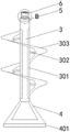
FIG. 1 is a cross-sectional view of an anchor-type and ribbon mixing and stirring device of the present invention;
FIG. 2 is a view showing the structure of the drum of the present invention;
FIG. 3 is a structural view of the rotating rod of the present invention;
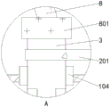
fig. 4 is a schematic view of the utility model at a;
fig. 5 is a schematic view of the position B of the present invention.
In the figure, 1, an apparatus main body; 101. a feed hopper; 102. a discharge pipe; 103. mounting a plate; 104. a bearing; 2. a motor; 201. a transmission belt; 3. a rotating drum; 301. a water outlet hole; 302. a connecting rod; 303. a helical ribbon; 4. a triangular frame; 401. a squeegee; 5. a limiting cylinder; 501. a first limit groove; 502. a second limit groove; 6. a hollow cylinder; 601. a limiting block; 7. a rotating rod; 701. a connecting plate; 702. an arc-shaped plate; 8. a water pipe; 801. and (5) mounting the head.
Detailed Description
The invention will be further described with reference to the accompanying drawings and specific embodiments to assist understanding of the invention. The method used in the utility model is a conventional method if no special regulation is provided; the raw materials and the apparatus used are, unless otherwise specified, conventional commercially available products.
Referring to fig. 1-5, the present invention provides the following technical solutions: the utility model provides an anchor formula and spiral shell area mix agitating unit, includes device main part 1, and the right side wall fixedly connected with mounting panel 103 of device main part 1, the up end of mounting panel 103 can be dismantled and be connected with motor 2, and the pivot outer wall cover of motor 2 is equipped with drive belt 201, and the opposite side cover of drive belt 201 inner wall is equipped with rotary drum 3, and the lower extreme of rotary drum 3 runs through device main part 1 and extends to the inside of device main part 1. The bearing 104 is sleeved between the rotary drum 3 and the device body 1, the spiral belt 303 is installed on the outer wall of the rotary drum 3, the triangular frame 4 is fixedly connected to the lower end of the rotary drum 3, and the scraper 401 is fixedly connected to the lower end of the triangular frame 4.
In this embodiment: to wait that the material of stirring puts into device main part 1 through feeder hopper 101, and starter motor 2 drives rotary drum 3 through drive belt 201 and is rotatory in device main part 1, and then drives spiral shell area 303 and rotates and stir the material in middle part. The materials are stirred and deposited downwards, and the materials deposited at the bottom of the device main body 1 can be stirred through the triangular frame 4 and the scraper 401, so that the effect of uniform stirring is achieved; hollow out form around being through setting up triangle frame 4, and then can reduce the resistance that receives when stirring the frame.
As a technical optimization scheme of the utility model, apopore 301 has all been seted up to the left and right sides of rotary drum 3, and first spacing groove 501 has all been seted up to the spacing section of thick bamboo 5 of upper end fixedly connected with of rotary drum 3, both sides around the 5 inner walls of a spacing section of thick bamboo, and second spacing groove 502 has all been seted up to the left and right sides of the 5 inner walls of a spacing section of thick bamboo. The inside through connection of rotary drum 3 has bull stick 7, the equal fixedly connected with connecting plate 701 in the left and right sides of bull stick 7, the equal fixedly connected with in one side that two connecting plate 701 carried on the back mutually and apopore 301 assorted arc 702, the upper end of bull stick 7 runs through rotary drum 3 and extends to the top of rotary drum 3, the hollow section of thick bamboo 6 of upper end fixedly connected with of bull stick 7, the equal fixedly connected with stopper 601 in the left and right sides of hollow section of thick bamboo 6, the upper end of hollow section of thick bamboo 6 is personally submitted netted, the outer wall rotation of a spacing section of thick bamboo 5 is connected with installation head 801, the up end intercommunication of installation.
In this embodiment: the upper end of the rotary drum 3 is communicated with the water pipe 8, and the other end of the water pipe 8 is connected with the water tap, so that water flows into the rotary drum 3 and is discharged through the two water outlet holes 301. Meanwhile, the motor 2 is started to drive the rotary drum 3 to rotate, so that the inner wall of the spiral belt 303 is cleaned by water flow; the upper end surface of the hollow cylinder 6 is in a net shape, so that water flow can conveniently flow into the rotary cylinder 3. After the cleaning is finished, the mounting head 801 and the limiting cylinder 5 are separated, the hollow cylinder 6 is pulled out upwards, the limiting block 601 is separated from the first limiting groove 501, then the hollow cylinder 6 is rotated, the limiting block 601 is clamped with the second limiting groove 502, and the two arc-shaped plates 702 are driven to rotate and respectively block the two water outlet holes 301, so that materials are prevented from entering the rotary cylinder 3.
As a technical optimization scheme of the utility model, the bottom of two first spacing grooves 501 and two second spacing grooves 502 is closed structure.
In this embodiment: the hollow cylinder 6 is moved downwards to drive the limiting block 601 to enter the limiting groove, and the limiting block 601 can be prevented from sliding downwards by the sealing structure at the bottom of the limiting groove, so that the positions of the rotating rod 7 and the two arc-shaped plates 702 are further fixed.
As a technical optimization scheme of the utility model, a plurality of connecting rods 302 of fixedly connected with between the outer wall of rotary drum 3 and spiral shell area 303.
In this embodiment: since the spiral belt 303 surrounds the outside of the drum 3 and is not directly connected to the drum 3, the position of the spiral belt 303 can be stably fixed by providing a plurality of connecting rods 302 between the spiral belt 303 and the drum 3.
The utility model discloses a theory of operation and use flow: to treat that the material of stirring puts into device main part 1 through feeder hopper 101, and starter motor 2 drives the rotary drum 3 through drive belt 201 and is rotatory in device main part 1, and then drives spiral shell area 303 and rotate and stir the material at middle part, and the material is through stirring downward sediment, and the material accessible triangle frame 4 and the scraper blade 401 that deposit in device main part 1 bottom stir. After the materials are discharged, the upper end of the rotary drum 3 is communicated with the water pipe 8, and the other end of the water pipe 8 is connected with a water tap, so that water flows into the rotary drum 3 and is discharged through the two water outlet holes 301; meanwhile, the motor 2 is started to drive the rotary drum 3 to rotate, so that the inner wall of the spiral belt 303 is cleaned by water flow. After the cleaning is finished, the mounting head 801 and the limiting cylinder 5 are separated, the hollow cylinder 6 is pulled out upwards, the limiting block 601 is separated from the first limiting groove 501, then the hollow cylinder 6 is rotated, the limiting block 601 is clamped with the second limiting groove 502, and the two arc-shaped plates 702 are driven to rotate and respectively block the two water outlet holes 301, so that materials are prevented from entering the rotary cylinder 3.
In the description of the present invention, it should be understood that the terms "left", "right", "upper", "lower", "top", "bottom", "front", "rear", "inner", "outer", "back", "middle", and the like indicate orientations or positional relationships based on the orientations or positional relationships shown in the drawings, and are only for convenience of description and simplicity of description, and do not indicate or imply that the device or element being referred to must have a particular orientation, be constructed and operated in a particular orientation, and therefore, should not be construed as limiting the present invention.
However, the above description is only an embodiment of the present invention, and the scope of the present invention should not be limited thereto, so that the replacement of the equivalent components or the equivalent changes and modifications made according to the protection scope of the present invention should be covered by the claims of the present invention.
Claims (6)
1. The utility model provides an anchor formula and spiral shell area mix agitating unit, includes device main part (1), its characterized in that: the utility model discloses a device, including device body (1), right side wall fixedly connected with mounting panel (103), the up end of mounting panel (103) can be dismantled and be connected with motor (2), the pivot outer wall cover of motor (2) is equipped with drive belt (201), the opposite side cover of drive belt (201) inner wall is equipped with rotary drum (3), the lower extreme of rotary drum (3) runs through device body (1) and extends to the inside of device body (1), the cover is equipped with bearing (104) between rotary drum (3) and device body (1), spiral shell area (303) are installed to the outer wall of rotary drum (3), the three angle frames (4) of lower extreme fixedly connected with of rotary drum (3), the lower extreme fixedly connected with scraper blade (401) of three angle frames (4).
2. The anchor and ribbon mixing and stirring device as claimed in claim 1, wherein: the water outlet holes (301) are formed in the left side and the right side of the rotary drum (3), the upper end of the rotary drum (3) is fixedly connected with a limiting drum (5), the front side and the rear side of the inner wall of the limiting drum (5) are respectively provided with a first limiting groove (501), the left side and the right side of the inner wall of the limiting drum (5) are respectively provided with a second limiting groove (502), the rotary drum (3) is connected with a rotary rod (7) in a penetrating manner, the left side and the right side of the rotary rod (7) are respectively and fixedly connected with a connecting plate (701), one side of each of the two connecting plates (701) opposite to each other is respectively and fixedly connected with an arc-shaped plate (702) matched with the water outlet holes (301), the upper end of the rotary rod (7) penetrates through the rotary drum (3) and extends to the upper part of the rotary drum (3), the upper end of the rotary rod, the upper end surface of the hollow cylinder (6) is in a net shape.
3. The anchor and ribbon mixing and stirring device as claimed in claim 2, wherein: the outer wall of the limiting barrel (5) is rotatably connected with an installing head (801), and the upper end face of the installing head (801) is communicated with a water pipe (8).
4. The anchor and ribbon mixing and stirring device as claimed in claim 1, wherein: the device is characterized in that the left side wall of the device main body (1) is communicated with a feed hopper (101), and the lower end surface of the device main body (1) is communicated with a discharge pipe (102).
5. The anchor and ribbon mixing and stirring device as claimed in claim 2, wherein: the bottoms of the two first limiting grooves (501) and the two second limiting grooves (502) are of closed structures.
6. The anchor and ribbon mixing and stirring device as claimed in claim 1, wherein: a plurality of connecting rods (302) are fixedly connected between the outer wall of the rotary drum (3) and the spiral belt (303).
Priority Applications (1)
| Application Number | Priority Date | Filing Date | Title |
|---|---|---|---|
| CN202021980120.XU CN213160468U (en) | 2020-09-11 | 2020-09-11 | Anchor type and spiral ribbon mixing and stirring device |
Applications Claiming Priority (1)
| Application Number | Priority Date | Filing Date | Title |
|---|---|---|---|
| CN202021980120.XU CN213160468U (en) | 2020-09-11 | 2020-09-11 | Anchor type and spiral ribbon mixing and stirring device |
Publications (1)
| Publication Number | Publication Date |
|---|---|
| CN213160468U true CN213160468U (en) | 2021-05-11 |
Family
ID=75772763
Family Applications (1)
| Application Number | Title | Priority Date | Filing Date |
|---|---|---|---|
| CN202021980120.XU Active CN213160468U (en) | 2020-09-11 | 2020-09-11 | Anchor type and spiral ribbon mixing and stirring device |
Country Status (1)
| Country | Link |
|---|---|
| CN (1) | CN213160468U (en) |
-
2020
- 2020-09-11 CN CN202021980120.XU patent/CN213160468U/en active Active
Similar Documents
| Publication | Publication Date | Title |
|---|---|---|
| CN208068575U (en) | A kind of concrete mixer | |
| CN213286701U (en) | Compound cauldron feeding auxiliary device of antistatic agent | |
| CN212021282U (en) | A melting material modification blending device for production of liquid traditional chinese medicine wrapping bag | |
| CN215610853U (en) | Centrifugal face cream compounding device convenient to it is clean | |
| CN212385700U (en) | Mortar mixer | |
| CN210278865U (en) | A rabbling mechanism for producing adhesive | |
| CN218077525U (en) | Coating mixing agitating unit for stirring convenient to it is clean | |
| CN215549762U (en) | Agitating unit is used in mortar production | |
| CN215311924U (en) | Concrete water-reducing agent processing is with agitating unit of ejection of compact of being convenient for | |
| CN213467581U (en) | Color matching stirring tank for coating | |
| CN215661048U (en) | Building cement stirring and distribution equipment for building engineering | |
| CN212978779U (en) | Mortar agitating unit that construction used | |
| CN213260282U (en) | Mixer is used in construction | |
| CN111501486A (en) | Mortar stirring irrigation equipment that sponge city was used | |
| CN112622045A (en) | Concrete mixing device for construction | |
| CN221287681U (en) | Material mixer for food production | |
| CN213193251U (en) | High-uniformity dry powder mixing device | |
| CN220559017U (en) | Slurry tank mixing stirrer | |
| CN220514040U (en) | Flexible paint stirrer | |
| CN220802846U (en) | Pig feed blendor | |
| CN221015527U (en) | Even compounding device is used in anti-caking agent production | |
| CN220047825U (en) | Printing ink preparation facilities with mixing of colors function | |
| CN213890598U (en) | Pile foundation intelligent construction equipment | |
| CN218365646U (en) | Mortar stirring device | |
| CN221819171U (en) | Compound agitator tank |
Legal Events
| Date | Code | Title | Description |
|---|---|---|---|
| GR01 | Patent grant | ||
| GR01 | Patent grant |