Flat plate support for solar cell panel
Technical Field
The utility model belongs to the technical field of solar cell panel, especially, relate to a plate holder for solar cell panel.
Background
The solar cell panel is a device which directly or indirectly converts solar radiation energy into electric energy through a photoelectric effect or a photochemical effect by absorbing sunlight, and most of the solar cell panels are made of silicon, but the manufacturing cost is high, so that the universal use of the solar cell panel has certain limitation. Compared with the common battery and the recyclable rechargeable battery, the solar battery belongs to a green product with more energy conservation and environmental protection,
traditional solar cell panel support is difficult for adjusting according to the angle of sun to influence solar cell panel's daylighting rate, bring inconvenience for the user.
SUMMERY OF THE UTILITY MODEL
An object of the utility model is to provide a plate holder for solar cell panel, worm through setting up, the second worm wheel, both mutually support, when needs adjust the angle of support, the worm drives two L shaped plates through the second worm wheel and rotates, thereby solar cell panel's daylighting rate has been improved, user's use has been made things convenient for, and the L shaped plate that sets up, when installing solar cell panel, the L shaped plate carries out the centre gripping to solar cell panel, solar cell panel produces the condition emergence of rocking when using has been reduced, thereby the stability of device has been increased, the problem that exists among the above-mentioned prior art has been solved.
In order to achieve the purpose, the utility model is realized by the following technical proposal:
a flat panel support for a solar panel, comprising: the support column is installed to the upside of base plate, and U-shaped plate subassembly is installed to the upside of support column, and U-shaped plate subassembly includes: a bottom plate and two first side plates; a connecting plate is arranged between the two first side plates, two fixed rings are arranged on the upper side of the connecting plate, a worm is rotatably matched between the two fixed rings, a rotating column is rotatably matched between the two first side plates, a first worm wheel is arranged on the peripheral side of the rotating column, a second side plate is slidably matched on the upper sides of the two first side plates, the cross section of the second side plate is semicircular, and a top plate is arranged between the two second side plates; the second worm wheel is installed to the downside of roof, and the second worm wheel cross-section is semi-circular, and first worm wheel, second worm wheel cooperate with the worm respectively, and the upside sliding fit of roof has two L shaped plates, is connected with two springs between two L shaped plates.
Optionally, a first groove is formed in one side of each of the two first side plates, and the second side plates are rotatably matched in the first grooves.
Optionally, a second groove is formed in the upper side of the connecting plate, the cross section of the second groove is semicircular, and the two fixing circular rings are located in the second groove.
Optionally, a through hole is formed in the lower side of the second groove, and the first worm wheel is rotatably matched with the through hole.
Optionally, the rotation column is located below the connection plate.
Optionally, two telescopic rods are installed between the two L-shaped plates, and the springs are respectively located on the periphery sides of the two telescopic rods.
The embodiment of the utility model has the following beneficial effect:
the utility model discloses an embodiment is through the worm that sets up, the second worm wheel, both mutually support, when the angle of support is adjusted to needs, the worm drives two L shaped plates through the second worm wheel and rotates, thereby solar cell panel's daylighting rate has been improved, user's use has been made things convenient for, and the L shaped plate that sets up, when installing solar cell panel, the L shaped plate carries out the centre gripping to solar cell panel, solar cell panel produces the condition emergence of rocking when using has been reduced, thereby the stability of device has been increased.
Of course, it is not necessary for any particular product to achieve all of the above-described advantages at the same time.
Drawings
The accompanying drawings, which form a part of the present application, are included to provide a further understanding of the invention, and are incorporated in and constitute a part of this specification, illustrate embodiments of the invention and together with the description serve to explain the invention and not to limit the invention. In the drawings:
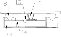
fig. 1 is a schematic perspective view of an embodiment of the present invention;
fig. 2 is a schematic structural view of a rotating column according to an embodiment of the present invention;
fig. 3 is a schematic structural diagram of a worm according to an embodiment of the present invention.
Wherein the figures include the following reference numerals:
the base plate comprises a base plate 1, a supporting column 2, a bottom plate 3, a first side plate 4, a rotating handle 5, a rotating column 6, a first worm wheel 7, a second side plate 8, a top plate 9, an L-shaped plate 10, an expansion rod 11, a second worm wheel 12, a worm 13 and a connecting plate 14.
Detailed Description
The technical solutions in the embodiments of the present invention will be described clearly and completely with reference to the accompanying drawings in the embodiments of the present invention, and it is obvious that the described embodiments are only some embodiments of the present invention, not all embodiments. The following description of at least one exemplary embodiment is merely illustrative in nature and is in no way intended to limit the invention, its application, or uses.
To maintain the following description of the embodiments of the present invention clear and concise, detailed descriptions of well-known functions and components may be omitted.
Referring to fig. 1 to 3, in the present embodiment, a flat plate rack for a solar cell panel is provided, including: support column 2 is installed to base plate 1, the upside of base plate 1, and U-shaped board subassembly is installed to the upside of support column 2, and U-shaped board subassembly includes: a bottom plate 3 and two first side plates 4; a connecting plate 14 is arranged between the two first side plates 4, two fixed circular rings are arranged on the upper side of the connecting plate 14, a worm 13 is rotatably matched between the two fixed circular rings, a rotating column 6 is rotatably matched between the two first side plates 4, a first worm wheel 7 is arranged on the peripheral side of the rotating column 6, second side plates 8 are slidably matched on the upper sides of the two first side plates 4, the cross sections of the second side plates 8 are semicircular, and a top plate 9 is arranged between the two second side plates 8; a second worm wheel 12 is mounted on the lower side of the top plate 9, the section of the second worm wheel 12 is semicircular, the first worm wheel 7 and the second worm wheel 12 are respectively matched with a worm 13, two L-shaped plates 10 are slidably matched on the upper side of the top plate 9, and two springs are connected between the two L-shaped plates 10.
The application of one aspect of the embodiment is as follows: when needs are adjusted solar cell panel support angle, at first rotate and rotate post 6, rotate post 6 and drive worm 13 through first worm wheel 7 and rotate, worm 13 drives roof 9 through second worm wheel 12 and rotates, and roof 9 drives L shaped plate 10 and removes to the completion is to the adjustment of solar cell panel support angle.
Through the worm 13 that sets up, second worm wheel 12, both mutually support, when the angle of needs to the support is adjusted, worm 13 drives two L shaped plates 10 through second worm wheel 12 and rotates, thereby solar cell panel's daylighting rate has been improved, user's use has been made things convenient for, and the L shaped plate 10 that sets up, when installing solar cell panel, L shaped plate 10 carries out the centre gripping to solar cell panel, solar cell panel when using has been reduced and the condition that solar cell panel produced and rocks takes place, thereby the stability of device has been increased.
First recess has all been seted up to one side of two first curb plate 4 of this embodiment, and second curb plate 8 normal running fit is in first recess.
The second recess has been seted up to the upside of the connecting plate 14 of this embodiment, and the cross-section semicircular in shape of second recess, two fixed rings are located the second recess.
The through-hole has been seted up to the downside of the second recess of this embodiment, in the first worm wheel 7 normal running fit through-hole.
The rotating column 6 of the present embodiment is located below the connecting plate 14.
Two telescopic rods 11 are installed between the two L-shaped plates 10 of this embodiment, and the springs are respectively located on the peripheral sides of the two telescopic rods 11.
The above embodiments may be combined with each other.
It should be noted that the terms "first," "second," and the like in the description and claims of this application and in the drawings described above are used for distinguishing between similar elements and not necessarily for describing a particular sequential or chronological order. It is to be understood that the data so used is interchangeable under appropriate circumstances such that the embodiments of the application described herein are capable of operation in sequences other than those illustrated or described herein.
In the description of the present invention, it should be understood that the orientation or positional relationship indicated by the orientation words such as "front, back, up, down, left, right", "horizontal, vertical, horizontal" and "top, bottom" etc. are usually based on the orientation or positional relationship shown in the drawings, and are only for convenience of description and simplification of description, and in the case of not making a contrary explanation, these orientation words do not indicate and imply that the device or element referred to must have a specific orientation or be constructed and operated in a specific orientation, and therefore, should not be interpreted as limiting the scope of the present invention; the terms "inner and outer" refer to the inner and outer relative to the profile of the respective component itself.