CN213149682U - Novel computer power supply protection device - Google Patents
Novel computer power supply protection device Download PDFInfo
- Publication number
- CN213149682U CN213149682U CN202022686025.5U CN202022686025U CN213149682U CN 213149682 U CN213149682 U CN 213149682U CN 202022686025 U CN202022686025 U CN 202022686025U CN 213149682 U CN213149682 U CN 213149682U
- Authority
- CN
- China
- Prior art keywords
- fixedly connected
- protection device
- box
- novel computer
- mounting panel
- Prior art date
- Legal status (The legal status is an assumption and is not a legal conclusion. Google has not performed a legal analysis and makes no representation as to the accuracy of the status listed.)
- Expired - Fee Related
Links
- 238000006243 chemical reaction Methods 0.000 claims abstract description 37
- 230000017525 heat dissipation Effects 0.000 claims abstract description 34
- 238000001816 cooling Methods 0.000 claims abstract description 8
- XLYOFNOQVPJJNP-UHFFFAOYSA-N water Substances O XLYOFNOQVPJJNP-UHFFFAOYSA-N 0.000 claims description 34
- 238000007789 sealing Methods 0.000 claims description 13
- 238000005507 spraying Methods 0.000 claims description 7
- 238000009434 installation Methods 0.000 claims description 5
- 230000005855 radiation Effects 0.000 claims 2
- 238000005516 engineering process Methods 0.000 abstract description 2
- 230000009977 dual effect Effects 0.000 description 2
- 230000000694 effects Effects 0.000 description 2
- 230000004075 alteration Effects 0.000 description 1
- 238000000034 method Methods 0.000 description 1
- 238000012986 modification Methods 0.000 description 1
- 230000004048 modification Effects 0.000 description 1
- 238000006467 substitution reaction Methods 0.000 description 1
Images




Landscapes
- Cooling Or The Like Of Electrical Apparatus (AREA)
Abstract
The utility model relates to a computer technology field specifically is a novel computer power protection device, including the seal box, the inside fixedly connected with pump body of seal box, the output fixedly connected with outlet pipe of the pump body, the tip fixedly connected with cooling tube of outlet pipe, cooling tube fixed connection in the inside of seal box, one side fixedly connected with radiator fan of seal box, the inside fixedly connected with heat dissipation case of seal box. The utility model has the advantages that: through setting up the clamp plate, at first place the power conversion adapter in the inside of mounting panel, later, make the power conversion adapter be located between two reference columns, later, remove the clamp plate, make the reference column pass in the inside locating hole of clamp plate, make the clamp plate be located the top of power conversion adapter, rotate the surface to the reference column with the locating piece, fix the clamp plate, realize the fixed to the power conversion adapter, simple structure is convenient for install and dismantle.
Description
Technical Field
The utility model relates to a computer technology field, especially a novel computer power protection device.
Background
With the rise of notebook computers and all-in-one machines, the power conversion adapter is also continuously improved as a supporting facility of electronic equipment, but when the computers run with high load, such as large games and a large number of background programs, the temperature of the power conversion adapter is high, if the heat can not be quickly and effectively dissipated, the power conversion adapter is easily burnt in a high-temperature working state continuously, and therefore the heat dissipation needs to be performed on the power conversion adapter.
The shortcomings of the current novel computer power protection device are as follows:
1. when the existing novel computer power protection device is used, heat dissipation is carried out by arranging heat dissipation holes on power equipment, so that the heat dissipation efficiency is low;
2. when the existing novel computer power protection device is used, power equipment needs to be cleaned and maintained frequently, and the installation and the disassembly are inconvenient.
SUMMERY OF THE UTILITY MODEL
An object of the utility model is to overcome prior art's shortcoming, provide a novel computer power protection device, solved the problem of proposing among the above-mentioned background art.
The purpose of the utility model is realized through the following technical scheme: a novel computer power supply protection device comprises a seal box, wherein a pump body is fixedly connected inside the seal box, an output end of the pump body is fixedly connected with a water outlet pipe, the end part of the water outlet pipe is fixedly connected with a radiating pipe, and the radiating pipe is fixedly connected inside the seal box;
one side of the sealing box is fixedly connected with a radiating fan, and the inside of the sealing box is fixedly connected with a radiating box;
a sliding groove is formed in the heat dissipation box, a sliding block is movably connected in the sliding groove, and an installation plate is fixedly connected to one side of the sliding block;
the bottom fixedly connected with locating plate of mounting panel, the top fixedly connected with reference column of mounting panel, the surface swing joint of reference column have the clamp plate, the surface swing joint of reference column have the locating piece, locating piece swing joint in the top of clamp plate.
Optionally, the two sides of the mounting plate are fixedly connected with sliding blocks, and the central lines of the sliding blocks and the mounting plate are collinear.
Optionally, the top of the seal box is provided with a water inlet hole, and the water inlet hole is fixedly connected with a water inlet pipe.
Optionally, one side of the mounting plate is fixedly connected with a fixing plate, and the fixing plate is fixedly connected with the seal box through a bolt.
Optionally, the both sides of mounting panel all fixedly connected with baffle, the baffle keep away from one side fixedly connected with handle of mounting panel.
Optionally, the input fixedly connected with oral siphon of the pump body, the cooling tube on seted up a plurality of hole for water spraying.
Optionally, the top of mounting panel be provided with power conversion adapter, power conversion adapter swing joint in the bottom of clamp plate, power conversion adapter's both sides all be provided with the electric wire that connects, the inside of baffle seted up the mounting hole, the electric wire that connects run through in the inside of mounting hole.
The utility model has the advantages of it is following:
1. this novel computer power protection device, through setting up the heat dissipation case, the heat dissipation case is located the inside of seal box, when using, fix the inside at the heat dissipation case with power conversion adapter, wherein the inside of seal box is provided with water, to the pump body circular telegram, make the inside water of seal box pass through the inside that the oral siphon got into the outlet pipe, later get into the inside of cooling tube, and spout to the heat dissipation case through the hole for water spraying, dispel the heat, radiator fan can be opened simultaneously, make the cold wind blow to the heat dissipation case, reach dual radiating purpose, the radiating effect is good.
2. This novel computer power protection device, through setting up the clamp plate, when fixing power conversion adapter, at first place the inside at the mounting panel with power conversion adapter, afterwards, make power conversion adapter be located between two reference columns, afterwards, remove the clamp plate, make the reference column pass in the inside locating hole of clamp plate, make the clamp plate be located the top of power conversion adapter, and rotate the surface to the reference column with the locating piece, fix the clamp plate, the realization is fixed power conversion adapter, moreover, the steam generator is simple in structure, and is convenient for install and dismantle.
Drawings
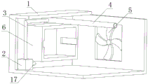
Fig. 1 is a schematic perspective view of the present invention;
FIG. 2 is a schematic structural view of the sealing box of the present invention;
FIG. 3 is a schematic structural view of the heat dissipating tube of the present invention;
FIG. 4 is a schematic structural view of the heat dissipation box of the present invention;
fig. 5 is a schematic structural view of the slide block of the present invention;
fig. 6 is a schematic structural view of the positioning plate of the present invention.
In the figure: 1-seal box, 2-pump body, 3-water outlet pipe, 4-radiating pipe, 5-radiating fan, 6-radiating box, 7-sliding chute, 8-sliding block, 9-mounting plate, 10-positioning plate, 11-positioning column, 12-pressing plate, 13-positioning block, 14-water inlet pipe, 15-fixing plate, 16-baffle, 17-water inlet pipe and 18-power adapter.
Detailed Description
The invention will be further described with reference to the accompanying drawings, but the scope of the invention is not limited to the following description.
As shown in fig. 1-6, a novel computer power protection device comprises a sealed box 1, a pump body 2 is fixedly connected inside the sealed box 1, an output end of the pump body 2 is fixedly connected with a water outlet pipe 3, an end part of the water outlet pipe 3 is fixedly connected with a radiating pipe 4, and the radiating pipe 4 is fixedly connected inside the sealed box 1;
one side of the sealing box 1 is fixedly connected with a radiating fan 5, and the inside of the sealing box 1 is fixedly connected with a radiating box 6; a sliding groove 7 is formed in the heat dissipation box 6, a sliding block 8 is movably connected in the sliding groove 7, and an installation plate 9 is fixedly connected to one side of the sliding block 8;
bottom fixedly connected with locating plate 10 of mounting panel 9, top fixedly connected with reference column 11 of mounting panel 9, the surface swing joint of reference column 11 has clamp plate 12, and the surface swing joint of reference column 11 has locating piece 13, and locating piece 13 swing joint is in the top of clamp plate 12.
As an optional technical solution of the utility model:
the slider 8 is fixedly connected to the two sides of the mounting plate 9, the center line of the slider 8 is collinear with the center line of the mounting plate 9, the slider 8 is located in the middle of the mounting plate 9, the mounting plate 9 can slide towards the two sides of the heat dissipation box 6 conveniently, and the two sides of the power conversion adapter 18 are connected in a wiring mode respectively.
As an optional technical solution of the utility model:
the inlet opening has been seted up at the top of seal box 1, and inlet opening department fixedly connected with inlet tube 14 is convenient for pass through inlet tube 14, makes water get into the inside of seal box 1.
As an optional technical solution of the utility model:
one side fixedly connected with fixed plate 15 of mounting panel 9, fixed plate 15 and seal box 1 pass through bolt fixed connection, use the bolt to fix fixed plate 15 in one side of seal box 1, are convenient for fix mounting panel 9 in the inside of heat dissipation case 6.
As an optional technical solution of the utility model:
the baffle 16 is fixedly connected to the two sides of the mounting plate 9, the handle is fixedly connected to one side, away from the mounting plate 9, of the baffle 16, the handle is pulled, the mounting plate 9 slides inside the heat dissipation box 6, and the power conversion adapter 18 is convenient to mount.
As an optional technical solution of the utility model:
the input fixedly connected with oral siphon 17 of the pump body 2 has seted up a plurality of hole for water spraying on the cooling tube 4, starts the pump body 2, makes the inside water of 1 inside of seal box get into the inside of outlet pipe 3 and cooling tube 4 through oral siphon 17 to discharge through the hole for water spraying, dispel the heat to the cooling box 6.
As an optional technical solution of the utility model:
the top of mounting panel 9 is provided with power conversion adapter 18, and power conversion adapter 18 swing joint is in the bottom of clamp plate 12, is convenient for fix power conversion adapter 18, is fit for installing not power conversion adapter 18 of equidimension, and the practicality is good.
The working process of the utility model is as follows: firstly, the device is moved to a proper position, a handle at one side of a baffle plate 16 is pulled to enable a mounting plate 9 to slide out of the interior of a heat dissipation box 6, a power conversion adapter 18 is placed in the mounting plate 9, the power conversion adapter 18 is located between two positioning columns 11, then a pressing plate 12 is moved to enable the positioning columns 11 to penetrate through positioning holes in the pressing plate 12, the pressing plate 12 is located at the top of the power conversion adapter 18, the positioning blocks 13 are rotated to the outer surfaces of the positioning columns 11 to fix the pressing plate 12, the power conversion adapter 18 is fixed, the structure is simple, the mounting and dismounting are convenient, the device is suitable for fixing power conversion adapters with different sizes, the practicability is good, then electric wires penetrate through mounting holes in the baffle plate 16 and are connected to the power conversion adapter 18, the mounting is completed, the baffle plate 16 is pushed, and the mounting plate 9 is located in the interior, and use the bolt, fix the fixed plate 15 in one side of the seal box 1, and then fix the mounting panel 9 in the inside of the heat dissipation box 6, through setting up the heat dissipation box 6, the heat dissipation box 6 is located in the inside of the seal box 1, when using, enter the inside of the seal box 1 through the inlet tube 14, wherein the height of water is greater than the bottom height of the heat dissipation box 6, energize the pump body 2, make the water inside the seal box 1 enter the inside of the outlet pipe 3 through the inlet tube 17, then enter the inside of the radiating pipe 4, and spout to the heat dissipation box 6 through the hole for water spraying, dispel the heat, the spun water can dispel the heat to the heat dissipation box 6, and flow to the inside of the seal box 1, realize circulating, can open the radiator fan 5 at the same time, make the cold wind blow to the heat dissipation box 6, reach the purpose of dual.
To sum up, when the novel computer power protection device is used, the heat dissipation box 6 is arranged, the heat dissipation box 6 is located inside the sealing box 1, the power conversion adapter 18 is fixed inside the heat dissipation box 6 when the novel computer power protection device is used, water is arranged inside the sealing box 1, the pump body 2 is electrified, the water inside the sealing box 1 enters the water outlet pipe 3 through the water inlet pipe 17 and then enters the heat dissipation pipe 4 and is sprayed to the heat dissipation box 6 through the water spraying holes to dissipate heat, meanwhile, the heat dissipation fan 5 can be opened, cold air is blown to the heat dissipation box 6, the purpose of double heat dissipation is achieved, and the heat dissipation effect is good; through setting up clamp plate 12, when fixing power conversion adapter 18, at first place power conversion adapter 18 in the inside of mounting panel 9, later, make power conversion adapter 18 be located between two reference columns 11, later, remove clamp plate 12, make reference column 11 pass in the inside locating hole of clamp plate 12, make clamp plate 12 be located power conversion adapter 18's top, and rotate locating piece 13 to reference column 11's surface, fix clamp plate 12, the realization is fixed power conversion adapter 18, moreover, the steam generator is simple in structure, and is convenient for installation and dismantlement.
Although embodiments of the present invention have been shown and described, it will be appreciated by those skilled in the art that changes, modifications, substitutions and alterations can be made in these embodiments without departing from the principles and spirit of the invention, the scope of which is defined in the appended claims and their equivalents.
Claims (7)
1. The utility model provides a novel computer power protection device which characterized in that: the water pump comprises a sealing box (1), wherein a pump body (2) is fixedly connected inside the sealing box (1), an output end of the pump body (2) is fixedly connected with a water outlet pipe (3), the end part of the water outlet pipe (3) is fixedly connected with a radiating pipe (4), and the radiating pipe (4) is fixedly connected inside the sealing box (1);
one side of the sealing box (1) is fixedly connected with a heat radiation fan (5), and the inside of the sealing box (1) is fixedly connected with a heat radiation box (6);
a sliding groove (7) is formed in the heat dissipation box (6), a sliding block (8) is movably connected in the sliding groove (7), and an installation plate (9) is fixedly connected to one side of the sliding block (8);
the bottom fixedly connected with locating plate (10) of mounting panel (9), the top fixedly connected with reference column (11) of mounting panel (9), the surface swing joint of reference column (11) have clamp plate (12), the surface swing joint of reference column (11) have locating piece (13), locating piece (13) swing joint in the top of clamp plate (12).
2. The novel computer power protection device of claim 1, wherein: the equal fixedly connected with slider (8) in both sides of mounting panel (9), the central line collineation of the central line of slider (8) and mounting panel (9).
3. The novel computer power protection device of claim 1, wherein: the top of the seal box (1) is provided with a water inlet hole, and a water inlet pipe (14) is fixedly connected to the water inlet hole.
4. The novel computer power protection device of claim 1, wherein: one side fixedly connected with fixed plate (15) of mounting panel (9), fixed plate (15) and seal box (1) pass through bolt fixed connection.
5. The novel computer power protection device of claim 1, wherein: the equal fixedly connected with baffle (16) in both sides of mounting panel (9), baffle (16) keep away from one side fixedly connected with handle of mounting panel (9).
6. The novel computer power protection device of claim 1, wherein: the input fixedly connected with oral siphon (17) of pump body (2), cooling tube (4) on seted up a plurality of hole for water spraying.
7. The novel computer power protection device of claim 1, wherein: the top of the mounting plate (9) is provided with a power conversion adapter (18), and the power conversion adapter (18) is movably connected to the bottom of the pressing plate (12).
Priority Applications (1)
| Application Number | Priority Date | Filing Date | Title |
|---|---|---|---|
| CN202022686025.5U CN213149682U (en) | 2020-11-19 | 2020-11-19 | Novel computer power supply protection device |
Applications Claiming Priority (1)
| Application Number | Priority Date | Filing Date | Title |
|---|---|---|---|
| CN202022686025.5U CN213149682U (en) | 2020-11-19 | 2020-11-19 | Novel computer power supply protection device |
Publications (1)
| Publication Number | Publication Date |
|---|---|
| CN213149682U true CN213149682U (en) | 2021-05-07 |
Family
ID=75722657
Family Applications (1)
| Application Number | Title | Priority Date | Filing Date |
|---|---|---|---|
| CN202022686025.5U Expired - Fee Related CN213149682U (en) | 2020-11-19 | 2020-11-19 | Novel computer power supply protection device |
Country Status (1)
| Country | Link |
|---|---|
| CN (1) | CN213149682U (en) |
-
2020
- 2020-11-19 CN CN202022686025.5U patent/CN213149682U/en not_active Expired - Fee Related
Similar Documents
| Publication | Publication Date | Title |
|---|---|---|
| CN206423035U (en) | A kind of strong charging pile Switching Power Supply of radiating effect | |
| CN110034500A (en) | A kind of distribution box of high-performance heat dissipation | |
| CN215771353U (en) | Drawer type multilayer power battery cabinet | |
| CN103687445A (en) | Electric cabinet water cooling and heat dissipation device | |
| CN206585455U (en) | A high-voltage inverter device with integrated air-water cooling and heat dissipation equipment inside | |
| CN210838484U (en) | High-low voltage switch cabinet with good heat dissipation effect | |
| CN221517882U (en) | Water cooling heat dissipation mechanism for explosion-proof robot and explosion-proof robot | |
| CN203675517U (en) | Electrical cabinet water-cooling heat dissipation device | |
| CN207624749U (en) | A kind of battery case radiator structure | |
| CN218070738U (en) | Switch board heat abstractor for mechanical and electrical engineering | |
| CN118736980A (en) | Ultra-thin touch-controlled liquid crystal display screen | |
| CN201750060U (en) | Box-type substation box body | |
| CN215817120U (en) | Construction is used prevents disorderly power distribution cabinet | |
| CN211406618U (en) | A power board protection device with waterproof function | |
| CN116113223A (en) | A communication integrated cabinet and its assembly method | |
| CN211531647U (en) | Signal acquisition's supervisor with heat dissipation function | |
| CN209861428U (en) | Heat dissipation device for high-frequency switching power supply | |
| CN207624496U (en) | A kind of cooling device suitable for power transformer | |
| CN211378627U (en) | Heat abstractor of remote control cabinet that building site used | |
| CN208016233U (en) | A kind of power communication heat-radiating dustproof device | |
| CN216436559U (en) | An energy-saving and power-saving control device for power distribution cabinet | |
| CN112752472A (en) | LED electronic screen with good heat dissipation effect | |
| CN207021556U (en) | A kind of ground source heat-dissipating formula power distribution cabinet | |
| CN214478933U (en) | Power cabinet air-cooling heat radiation structure | |
| CN223552950U (en) | A heat dissipation type nuclear power plant-specific trough-type cable tray |
Legal Events
| Date | Code | Title | Description |
|---|---|---|---|
| GR01 | Patent grant | ||
| GR01 | Patent grant | ||
| CF01 | Termination of patent right due to non-payment of annual fee |
Granted publication date: 20210507 Termination date: 20211119 |
|
| CF01 | Termination of patent right due to non-payment of annual fee |