CN213125332U - An underground box-type substation with moisture-proof function - Google Patents

An underground box-type substation with moisture-proof function Download PDF

Info

Publication number
CN213125332U
CN213125332U CN202021978137.1U CN202021978137U CN213125332U CN 213125332 U CN213125332 U CN 213125332U CN 202021978137 U CN202021978137 U CN 202021978137U CN 213125332 U CN213125332 U CN 213125332U
Authority
CN
China
Prior art keywords
fixedly connected
plate
connecting plate
moisture
mount
Prior art date
Legal status (The legal status is an assumption and is not a legal conclusion. Google has not performed a legal analysis and makes no representation as to the accuracy of the status listed.)
Active
Application number
CN202021978137.1U
Other languages
Chinese (zh)
Inventor
吴进鹏
吴运茂
杨磊
杨晶
Current Assignee (The listed assignees may be inaccurate. Google has not performed a legal analysis and makes no representation or warranty as to the accuracy of the list.)
Xi'an Yuxiang Electrical Engineering Co ltd
Original Assignee
Xi'an Yuxiang Electrical Engineering Co ltd
Priority date (The priority date is an assumption and is not a legal conclusion. Google has not performed a legal analysis and makes no representation as to the accuracy of the date listed.)
Filing date
Publication date
Application filed by Xi'an Yuxiang Electrical Engineering Co ltd filed Critical Xi'an Yuxiang Electrical Engineering Co ltd
Priority to CN202021978137.1U priority Critical patent/CN213125332U/en
Application granted granted Critical
Publication of CN213125332U publication Critical patent/CN213125332U/en
Active legal-status Critical Current
Anticipated expiration legal-status Critical

Links

Images

Landscapes

  • Underground Structures, Protecting, Testing And Restoring Foundations (AREA)

Abstract

本实用新型涉及变电站技术领域,尤其为一种具有防潮功能的地埋箱式变电站,包括连接板、固定架和变电站本体,所述固定架内设置有变电站本体,所述变电站本体底端通过垫片与支撑板固定连接,所述支撑板上端固定连接有支撑杆,所述支撑杆上端固定连接在连接板底端,本实用新型通过设置风扇和通气管可以对装置内的空气进行排出,可以起到降温与去潮气的作用,通过设置拉杆可以对防潮剂进行快速更换,放置因为防潮剂而导致防潮效果不佳,增加实用性,通过设置电机,可以使支撑板带动变电站本体上升,同时滑轮可以防止在上升的过程中卡死,方便对装置进行维修与检测,防止装置出现故障时,影响维修效率,造成不必要的事故。
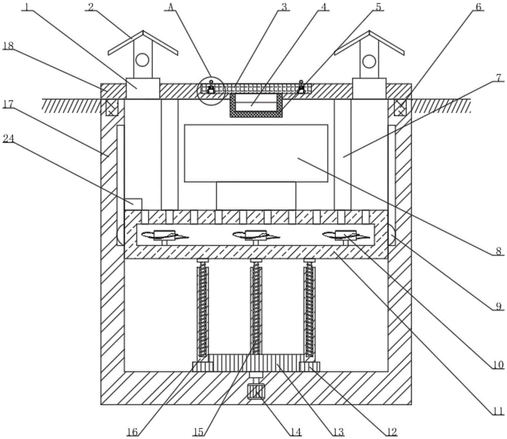
Figure 202021978137

The utility model relates to the technical field of substations, in particular to an underground box-type substation with moisture-proof function, comprising a connecting plate, a fixing frame and a substation body, wherein the fixing frame is provided with a substation body, and the bottom end of the substation body passes through a pad The plate is fixedly connected to the support plate, the upper end of the support plate is fixedly connected with a support rod, and the upper end of the support rod is fixedly connected to the bottom end of the connecting plate. It plays the role of cooling and removing moisture. The moisture-proof agent can be quickly replaced by setting the pull rod. The moisture-proof effect is not good due to the moisture-proof agent, which increases the practicability. By setting the motor, the support plate can drive the substation body to rise. It can prevent the device from being stuck in the process of rising, which is convenient for maintenance and detection of the device, and prevents the device from malfunctioning, which affects the maintenance efficiency and causes unnecessary accidents.

Figure 202021978137

Description

Bury box-type substation with dampproofing function
Technical Field
The utility model relates to a transformer substation technical field specifically is a bury box-type substation with dampproofing function.
Background
The buried transformer substation is characterized in that the traditional box transformer substation and the semi-buried box transformer substation are completely buried under the ground, the use of the box transformer substation is not influenced by the ground, and the buried transformer substation has the advantages of environmental protection, energy conservation, theft prevention, no noise, no radiation, debris flow resistance, flood resistance and good sealing property. The method has the advantages of saving land, improving the land utilization rate, reducing the capital investment and the like, and along with the development of the society, the application of the buried box type transformer substation with the moisture-proof function is increasingly wide.
Bury box-type substation on the market mostly and do not have dampproofing and function of cooling, lead to the device to receive the damage easily, influence the use, still can lead to device life to shorten to do not have automatic rising's effect, when leading to needing the maintenance device, can not maintain the very first time, probably lead to maintenance efficiency low, miss best maintenance time.
SUMMERY OF THE UTILITY MODEL
An object of the utility model is to provide a bury box-type substation with dampproofing function to solve the problem that proposes in the above-mentioned background art.
In order to achieve the above object, the utility model provides a following technical scheme:
a buried box type transformer substation with a damp-proof function comprises a connecting plate, a fixing frame and a transformer substation body, wherein the transformer substation body is arranged in the fixing frame, the bottom end of the transformer substation body is fixedly connected with a supporting plate through a gasket, a supporting rod is fixedly connected to the upper end of the supporting plate, the upper end of the supporting rod is fixedly connected to the bottom end of the connecting plate, a groove is formed in the upper end of the connecting plate, a fixing plate is slidably connected to the groove in the connecting plate, fixing sleeves are slidably connected to the left end and the right end of the fixing plate, the fixing sleeves are fixedly connected to the connecting plate, a pressing block is slidably connected to the left end and the right end of the pressing block, clamping balls are slidably connected to the left end and the right end of the fixing sleeve, the, the utility model discloses a moisture-proof and moisture-proof device, including pull rod, spring, fixed plate bottom fixed connection, place the net and pass the connecting plate bottom, place the net setting in the mount, place the interior sliding connection of net and have the dampproof agent.
Preferably, the fixed sleeve is provided with two, two the fixed sleeve is symmetrical along the perpendicular line in the fixed plate, the bracing piece is provided with four, backup pad upper end left side fixedly connected with controller.
Preferably, fixedly connected with fan in the backup pad, the fan is provided with a plurality ofly, the exhaust hole has been seted up to the backup pad upper end, connecting plate upper end fixedly connected with breather pipe, the breather pipe is provided with two, two the equal fixedly connected with weather shield in breather pipe upper end.
Preferably, both ends are rotated and are connected with the pulley about the backup pad, pulley sliding connection is in the slide rail on both ends about the mount, sliding connection has the go-between in the mount upper end, go-between fixed connection is in the connecting plate bottom.
Preferably, the interior of mount bottom is rotated through the pivot and is connected with the driving gear, driving gear bottom is through shaft coupling and motor output shaft fixed connection, be provided with driven gear around the driving gear, the driving gear is connected with driven gear meshing, driven gear rotates and connects in the mount bottom, driven gear upper end fixedly connected with dead lever, dead lever inner gearing is connected with the threaded rod, threaded rod upper end fixed connection is in the backup pad bottom.
Compared with the prior art, the beneficial effects of the utility model are that:
1. the utility model discloses in, through fan, breather pipe, pull rod and the dampproof agent that sets up, can discharge the air in the device through setting up fan and breather pipe, can play the effect of cooling and moisture removal, can carry out quick replacement to the dampproof agent through setting up the pull rod, place because the dampproof agent leads to dampproofing effect not good, increase the practicality.
2. The utility model discloses in, through motor, backup pad and the pulley that sets up, through setting up the motor, can make the backup pad drive the transformer substation body and rise, the pulley can prevent to die at the in-process card that rises simultaneously, and the convenience is maintained and is detected the device, and when preventing that the device from breaking down, influences maintenance efficiency, causes the unnecessary accident.
Drawings
Fig. 1 is a schematic view of the overall structure of the present invention;
fig. 2 is a schematic structural diagram of a portion a of fig. 1 according to the present invention.
In the figure: 1-vent pipe, 2-rain baffle, 3-fixed plate, 4-moisture-proof agent, 5-placing net, 6-connecting ring, 7-supporting rod, 8-transformer substation body, 9-pulley, 10-fan, 11-supporting plate, 12-driven gear, 13-driving gear, 14-motor, 15-threaded rod, 16-fixed rod, 17-fixed frame, 18-connecting plate, 19-spring, 20-pull rod, 21-pressing block, 22-fixed sleeve, 23-clamping ball and 24-controller.
Detailed Description
The technical solutions in the embodiments of the present invention will be described clearly and completely with reference to the accompanying drawings in the embodiments of the present invention, and it is obvious that the described embodiments are only some embodiments of the present invention, not all embodiments. Based on the embodiments in the present invention, all other embodiments obtained by a person skilled in the art without creative work belong to the protection scope of the present invention.
Referring to fig. 1-2, the present invention provides a technical solution:
a buried box type transformer substation with a damp-proof function comprises a connecting plate 18, a fixing frame 17 and a transformer substation body 8, wherein the transformer substation body 8 is arranged in the fixing frame 17, the bottom end of the transformer substation body 8 is fixedly connected with a supporting plate 11 through a gasket, the upper end of the supporting plate 11 is fixedly connected with a supporting rod 7, the connecting plate 18 is supported through the supporting rod 7, the upper end of the supporting rod 7 is fixedly connected with the bottom end of the connecting plate 18, the upper end of the connecting plate 18 is provided with a groove, a fixing plate 3 is connected in the groove on the connecting plate 18 in a sliding manner, fixing sleeves 22 are connected in the left end and the right end of the fixing plate 3 in a sliding manner, the fixing sleeves 22 are fixedly connected on the connecting plate 18, press blocks 21 are connected in the fixing sleeves 22 in a sliding manner, clamp balls 23 are, pull rod 20 passes 3 upper ends of fixed plate, pull rod 20 and 3 sliding connection of fixed plate, both ends are provided with spring 19 about pull rod 20, spring 19 upper end fixed connection is in fixed plate 3, 19 bottom fixed connection of spring is in 21 upper ends of briquetting, can dismantle fixed plate 3 fast, 3 bottom fixed connection of fixed plate place net 5, place net 5 and pass 18 bottoms of connecting plate, place net 5 and set up in mount 17, place and slide connection in net 5 has dampproof agent 4, can change dampproof agent 4.
The number of the fixed sleeves 22 is two, the two fixed sleeves 22 are symmetrical along the vertical line in the fixed plate 3, the number of the support rods 7 is four, the controller 24 is fixedly connected to the left side of the upper end of the support plate 11, and the controller 24 is used for controlling the device; the fan 10 is fixedly connected in the supporting plate 11, the number of the fans 10 is multiple, the upper end of the supporting plate 11 is provided with an exhaust hole, the upper end of the connecting plate 18 is fixedly connected with two vent pipes 1, the upper ends of the two vent pipes 1 are fixedly connected with rain baffles 2, and air in the device can be exhausted through the vent pipes 1; pulleys 9 are rotatably connected to the left end and the right end of the supporting plate 11, the pulleys 9 are slidably connected into sliding rails on the left end and the right end of the fixing frame 17, a connecting ring 6 is slidably connected to the upper end of the fixing frame 17, the connecting ring 6 is fixedly connected to the bottom end of the connecting plate 18, and the device can be prevented from being locked in the ascending process through the pulleys 9; be connected with driving gear 13 through the pivot rotation in the mount 17 bottom, driving gear 13 bottom is through shaft coupling and 14 output shaft fixed connection of motor, be provided with driven gear 12 around the driving gear 13, driving gear 13 is connected with the meshing of driven gear 12, driven gear 12 rotates and connects in mount 17 bottom, 12 upper end fixedly connected with dead lever 16 of driven gear, 16 inner gearing of dead lever is connected with threaded rod 15, 15 upper end fixed connection of threaded rod are in 11 bottoms of backup pad, can go up and down to transformer substation's body 8.
The working process is as follows: the utility model supplies power through the external power supply before using, when the ground is buried in the box-type substation and is dampproof, the moisture in the ground is buried in the box-type substation is absorbed through the moisture-proof agent 4, and the moisture is blown out through the fan 10 and is discharged through the vent pipe 1, and the device can be radiated when the weather is hot, when the moisture-proof agent 4 needs to be replaced, the pull rod 20 is pulled, the pull rod 20 drives the pressing block 21 to move, the pressing block 21 can contact the extrusion to the clamping ball 23, at the moment, the fixing plate 3 is pulled, the fixing sleeve 22 leaves the fixing plate 3, the disassembly of the placing net 5 is completed, the moisture-proof agent 4 on the upper surface can be replaced, when the fixing plate 3 is fixed, the placing net 5 is inserted into the fixing frame 17, the fixing sleeve 22 enters the fixing plate 3, when the pressing block 21 enters the fixing sleeve 22 due to the action of the spring 19, when simultaneously squeezing calorie ball 23, fixed plate 3 has just been accomplished, when needs bury box-type substation to ground and maintain, open motor 14 through controller 24, motor 14 can drive driving gear 13 and rotate, driving gear 13 drives driven gear 12 and rotates, driven gear 12 drives dead lever 16 and rotates, dead lever 16 can drive threaded rod 15 and upwards move, threaded rod 15 drives backup pad 11 and upwards moves, backup pad 11 can drive transformer substation's body 8 and come out from ground, can maintain it, after the maintenance is accomplished, open motor 14 through controller 24, make threaded rod 15 drive transformer substation's body 8 return to original position, go-between 6 gets into in mount 17 simultaneously, can prevent that the rainwater from getting into.
Although embodiments of the present invention have been shown and described, it will be appreciated by those skilled in the art that changes, modifications, substitutions and alterations can be made in these embodiments without departing from the principles and spirit of the invention, the scope of which is defined in the appended claims and their equivalents.

Claims (5)

1. The utility model provides a bury box-type substation with dampproofing function, includes connecting plate (18), mount (17) and transformer substation body (8), its characterized in that: a transformer substation body (8) is arranged in the fixing frame (17), the bottom end of the transformer substation body (8) is fixedly connected with the supporting plate (11) through a gasket, the upper end of the supporting plate (11) is fixedly connected with the supporting rod (7), the upper end of the supporting rod (7) is fixedly connected with the bottom end of the connecting plate (18), a groove is formed in the upper end of the connecting plate (18), a fixing plate (3) is connected in the groove in the connecting plate (18) in a sliding manner, fixing sleeves (22) are connected in the left end and the right end of the fixing plate (3) in a sliding manner, the fixing sleeves (22) are fixedly connected on the connecting plate (18), press blocks (21) are connected in the fixing sleeves (22) in a sliding manner, clamping balls (23) are connected in the left end and the right end of the press blocks (21) in a sliding manner, briquetting (21) upper end fixed block is connected with pull rod (20), fixed plate (3) upper end is passed in pull rod (20), pull rod (20) and fixed plate (3) sliding connection, both ends are provided with spring (19) about pull rod (20), spring (19) upper end fixed connection is in fixed plate (3), spring (19) bottom fixed connection is in briquetting (21) upper end, net (5) are placed to fixed plate (3) bottom fixed connection, place net (5) and pass connecting plate (18) bottom, place net (5) and set up in mount (17), place in net (5) sliding connection have dampproof agent (4).
2. The underground substation with moisture-proof function according to claim 1, characterized in that: the fixed sleeve (22) is provided with two, two the fixed sleeve (22) is symmetrical along the perpendicular line in fixed plate (3), bracing piece (7) are provided with four, backup pad (11) upper end left side fixedly connected with controller (24).
3. The underground substation with moisture-proof function according to claim 1, characterized in that: fixedly connected with fan (10) in backup pad (11), fan (10) are provided with a plurality ofly, the exhaust hole has been seted up to backup pad (11) upper end, connecting plate (18) upper end fixedly connected with breather pipe (1), breather pipe (1) is provided with two, two equal fixedly connected with weather shield (2) in breather pipe (1) upper end.
4. The underground substation with moisture-proof function according to claim 1, characterized in that: both ends are rotated and are connected with pulley (9) about backup pad (11), pulley (9) sliding connection is in the slide rail on both ends about mount (17), sliding connection has go-between (6) in mount (17) upper end, go-between (6) fixed connection is in connecting plate (18) bottom.
5. The underground substation with moisture-proof function according to claim 1, characterized in that: the utility model discloses a motor, including mount (17), driving gear (13) bottom, driven gear (12), driven gear (13) and motor (14), output shaft fixed connection is passed through the shaft coupling in mount (17) bottom, be provided with driven gear (12) around driving gear (13), driving gear (13) are connected with driven gear (12) meshing, driven gear (12) rotate to be connected in mount (17) bottom, driven gear (12) upper end fixedly connected with dead lever (16), dead lever (16) inner gearing is connected with threaded rod (15), threaded rod (15) upper end fixed connection is in backup pad (11) bottom.
CN202021978137.1U 2020-09-11 2020-09-11 An underground box-type substation with moisture-proof function Active CN213125332U (en)

Priority Applications (1)

Application Number Priority Date Filing Date Title
CN202021978137.1U CN213125332U (en) 2020-09-11 2020-09-11 An underground box-type substation with moisture-proof function

Applications Claiming Priority (1)

Application Number Priority Date Filing Date Title
CN202021978137.1U CN213125332U (en) 2020-09-11 2020-09-11 An underground box-type substation with moisture-proof function

Publications (1)

Publication Number Publication Date
CN213125332U true CN213125332U (en) 2021-05-04

Family

ID=75661506

Family Applications (1)

Application Number Title Priority Date Filing Date
CN202021978137.1U Active CN213125332U (en) 2020-09-11 2020-09-11 An underground box-type substation with moisture-proof function

Country Status (1)

Country Link
CN (1) CN213125332U (en)

Cited By (1)

* Cited by examiner, † Cited by third party
Publication number Priority date Publication date Assignee Title
CN115533852A (en) * 2022-10-21 2022-12-30 国网黑龙江省电力有限公司电力科学研究院 Insulation protection device for transformer maintenance

Cited By (1)

* Cited by examiner, † Cited by third party
Publication number Priority date Publication date Assignee Title
CN115533852A (en) * 2022-10-21 2022-12-30 国网黑龙江省电力有限公司电力科学研究院 Insulation protection device for transformer maintenance

Similar Documents

Publication Publication Date Title
CN112398025B (en) Buried transformer substation with low-fault physical heat dissipation
CN113054567B (en) A low-voltage outdoor distribution cabinet
CN220325554U (en) Photovoltaic power generation equipment protection structure for severe environment
CN113346837B (en) Solar power generation device with protection function
CN115954784A (en) A new type of low-voltage JP cabinet that is dust-proof, leak-proof and rain-proof
CN110600225B (en) A pole-mounted transformer rainwater cooling device
CN221461647U (en) Waterproof structure of light steel structure house roof
CN116065875B (en) Environmental protection construction enclosure with warning function and use method
CN216952858U (en) Complementary intelligent LED solar street lamp of commercial power
CN218973310U (en) An adjustable dust-proof device for an open circulating water cooling tower
CN117601090A (en) An alloy hard tool storage rack with self-cleaning function
CN216214868U (en) An outdoor rainproof power distribution cabinet based on buoyancy I-shaped water seal structure
CN118129098A (en) Adjustable new energy street lamp and use method
CN222423605U (en) A solar powered gas detection device
CN218119621U (en) Street lamp convenient to installation
CN221978437U (en) A power cabinet for power construction
CN219035381U (en) Upper braking structure suitable for air cooling cleaning device
CN217036374U (en) A multifunctional outdoor power distribution cabinet
CN222036246U (en) A positioning device for pipeline cleaning
CN222321793U (en) Heat dissipation type protection device of cast aluminum heater
CN221202971U (en) External power supply protection structure with heat radiation structure for electronic engineering
CN221664365U (en) An outdoor generator shed
CN221895631U (en) An intelligent safety warning device for building construction that can utilize solar energy
CN218162013U (en) Outer side rainproof mechanism for roller shutter door
CN221609649U (en) An assembled photovoltaic carport that is easy to drain

Legal Events

Date Code Title Description
GR01 Patent grant
GR01 Patent grant
PE01 Entry into force of the registration of the contract for pledge of patent right

Denomination of utility model: A buried box substation with moisture-proof function

Effective date of registration: 20231016

Granted publication date: 20210504

Pledgee: Xi'an Caijin Financing Guarantee Co.,Ltd.

Pledgor: XI'AN YUXIANG ELECTRICAL ENGINEERING Co.,Ltd.

Registration number: Y2023980061224

PC01 Cancellation of the registration of the contract for pledge of patent right

Granted publication date: 20210504

Pledgee: Xi'an Caijin Financing Guarantee Co.,Ltd.

Pledgor: XI'AN YUXIANG ELECTRICAL ENGINEERING Co.,Ltd.

Registration number: Y2023980061224