CN213121059U - Production of two filter switches is with detecting frock - Google Patents
Production of two filter switches is with detecting frock Download PDFInfo
- Publication number
- CN213121059U CN213121059U CN202021933836.4U CN202021933836U CN213121059U CN 213121059 U CN213121059 U CN 213121059U CN 202021933836 U CN202021933836 U CN 202021933836U CN 213121059 U CN213121059 U CN 213121059U
- Authority
- CN
- China
- Prior art keywords
- plate
- grooves
- connecting rods
- rods
- production
- Prior art date
- Legal status (The legal status is an assumption and is not a legal conclusion. Google has not performed a legal analysis and makes no representation as to the accuracy of the status listed.)
- Expired - Fee Related
Links
- 238000004519 manufacturing process Methods 0.000 title claims abstract description 19
- 238000001514 detection method Methods 0.000 claims abstract description 30
- 230000003287 optical effect Effects 0.000 claims abstract description 5
- 230000000087 stabilizing effect Effects 0.000 claims description 12
- 230000007246 mechanism Effects 0.000 claims description 11
- 230000000903 blocking effect Effects 0.000 claims 1
- 244000309464 bull Species 0.000 description 6
- 238000000034 method Methods 0.000 description 3
- 230000009286 beneficial effect Effects 0.000 description 2
- 230000006835 compression Effects 0.000 description 2
- 238000007906 compression Methods 0.000 description 2
- 238000010586 diagram Methods 0.000 description 2
- 230000000694 effects Effects 0.000 description 1
- 238000007689 inspection Methods 0.000 description 1
- 239000000463 material Substances 0.000 description 1
- 239000004033 plastic Substances 0.000 description 1
- 229920003023 plastic Polymers 0.000 description 1
- 230000000284 resting effect Effects 0.000 description 1
Images


Landscapes
- Geophysics And Detection Of Objects (AREA)
Abstract
The utility model provides a two optical filter switch production are with detecting frock. The detection tool for producing the double-optical filter switcher comprises a base; a placing plate disposed above the base; the plurality of shelving grooves are formed in the top of the placing plate; the through grooves are respectively formed in the inner walls of the bottoms of the placing grooves; the linkage plate is arranged above the placing plate; the detection matching holes are formed in the top of the linkage plate and are matched with the placement grooves; the two supporting and connecting rods are arranged on the placing plate in a sliding mode, and the top ends of the supporting and connecting rods are fixedly connected with the linkage plate. The utility model provides a two optical filter switch production are with detecting frock has the advantage that the tight mode of clamp safe and reliable, reduction friction vestige produced, improve detection efficiency.
Description
Technical Field
The utility model relates to a detect frock technical field, especially relate to a two optical filter switch production are with detecting frock.
Background
The double-optical-filter switcher is characterized in that a group of filters are arranged in a camera lens group, when infrared sensing points outside the camera lens detect the intensity change of light, the built-in IR-CUT automatic switching filters can automatically switch along with the intensity of external light, so that an image achieves the best effect, at the present stage, after the double-optical-filter switcher is manufactured, the use performance of the double-optical-filter switcher needs to be comprehensively detected, so that whether the double-optical-filter switcher is qualified can be known, and the double-optical-filter switcher needs to be clamped by a corresponding tool for detection when detection is performed.
However, traditional detection frock is when using, and the cooperation that is direct through bolt and splint is mostly, and is direct to press from both sides two filter switches hard tight, presss from both sides the friction vestige with the plastics shell of two filter switches very easily to detection at every turn, traditional frock can only press from both sides a two filter switches tightly and carry out subsequent detection work, later the manual work take out again, and detection efficiency is lower.
Therefore, it is necessary to provide a new inspection tool for producing a dual-filter switcher, so as to solve the above technical problems.
SUMMERY OF THE UTILITY MODEL
The utility model provides a technical problem provide a press from both sides tight mode safe and reliable, reduce the friction vestige and produce, improve detection efficiency's two optical filter switch production with detecting frock.
In order to solve the technical problem, the utility model provides a production of two filter switches is with detecting frock includes: a base; a placing plate disposed above the base; the plurality of shelving grooves are formed in the top of the placing plate; the through grooves are respectively formed in the inner walls of the bottoms of the placing grooves; the linkage plate is arranged above the placing plate; the detection matching holes are formed in the top of the linkage plate and are matched with the placement grooves; the two supporting and connecting rods are arranged on the placing plate in a sliding mode, and the top ends of the supporting and connecting rods are fixedly connected with the linkage plate; the push plate is arranged below the placing plate, and the top of the push plate is fixedly connected with the supporting and connecting rod; the hollow column is fixedly arranged at the bottom of the push plate; the screw rod is rotatably installed at the bottom of the base, and the top end of the screw rod extends into the hollow column and is in threaded connection with the inner wall of the bottom of the hollow column; the ring bodies are fixedly arranged at the bottom of the linkage plate and are respectively matched with the detection matching holes; the plurality of buffer mechanisms are respectively arranged on the plurality of ring bodies; the ejection mechanism is arranged above the push plate.
Preferably, buffer gear includes that two are accomodate logical groove, two depression bars, two rubber pads, two firm poles and two springs, two accomodate logical groove and all set up in the bottom of ring body, two the depression bar is slidable mounting respectively two accomodate on the inner wall of logical groove, the bottom of depression bar extends to the below of ring body, two the rubber pad is fixed mounting respectively two the bottom of depression bar, two firm pole fixed mounting respectively is two the top of depression bar, two the top of firm pole extend to the top of linkage plate and with the bottom inner wall sliding connection of linkage plate, two the spring overlaps respectively and establishes two on the firm pole, two the top of spring all with linkage plate fixed connection, two the bottom of spring respectively with two depression bar fixed connection.
Preferably, ejection mechanism includes diaphragm, a plurality of roof, two link rods and two cylinders, the diaphragm sets up the top of push pedal, and is a plurality of the roof sets up respectively in a plurality of logical inslot, two the equal fixed mounting of link rod is in the bottom of diaphragm, the bottom of link rod extends to the below of push pedal, the link rod runs through the push pedal and with push pedal swing joint, two the equal fixed mounting of cylinder is in the top of base, two the output shaft of cylinder respectively with two the bottom fixed connection of link rod.
Preferably, two side plates are fixedly mounted at the top of the base, and one sides of the two side plates, which are close to each other, are fixedly connected with two sides of the placing plate respectively.
Preferably, the top end of the stabilizing rod is fixedly provided with a position abutting block.
Preferably, a plurality of connecting rods are fixedly mounted at the top of the transverse plate, and the top ends of the connecting rods respectively extend into the through grooves and are fixedly connected with the corresponding top plates.
Preferably, two avoiding holes are formed in the top of the push plate, the connecting rod penetrates through the avoiding holes and is movably connected with the inner walls of the avoiding holes, and the avoiding holes are matched with the air cylinders.
Preferably, the screw rod is fixedly sleeved with a rotating rod, and the top end of the screw rod is fixedly provided with a baffle.
Compared with the prior art, the utility model provides a two light filter switch production are with detecting frock has following beneficial effect:
the utility model provides a production of two filter switches is with detecting frock, when detecting, put into a plurality of holding inslot respectively with a plurality of two filter switches, then clockwise rotation bull stick, under the screw thread relation between screw rod and the hollow post, the linkage board just can descend, after the rubber pad contacts two filter switches, continue to rotate the bull stick two to three circles, make the spring atress compress, give the depression bar a reverse force, reliably compress tightly two filter switches, subsequently detect the work, after detecting, reverse rotation bull stick, separate rubber pad and two filter switches, then start the output shaft of cylinder and stretch out, push out two filter switches, then take out it easily, need not to scratch it earlier and take away again, saved and got the material process, and every round can detect a plurality of two filter switches, further improved detection efficiency, and the arrangement of the rubber pad greatly reduces friction marks generated on the double-optical-filter switcher when the double-optical-filter switcher is clamped.
Drawings
Fig. 1 is a schematic structural diagram of a detection tool for producing a dual-filter switcher according to a preferred embodiment of the present invention;
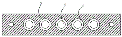
FIG. 2 is a schematic top view of the plate of the present invention;
fig. 3 is an enlarged schematic view of a portion a shown in fig. 1.
Reference numbers in the figures: 1. a base; 2. placing the plate; 3. a resting groove; 4. a through groove; 5. a linkage plate; 6. detecting the matching hole; 7. a support rod; 8. pushing the plate; 9. a hollow column; 10. a screw; 11. a ring body; 12. a storage through groove; 13. a pressure lever; 14. a rubber pad; 15. a stabilizing rod; 16. a spring; 17. a transverse plate; 18. a top plate; 19. a connecting rod; 20. and a cylinder.
Detailed Description
The present invention will be further described with reference to the accompanying drawings and embodiments.
Please refer to fig. 1, fig. 2 and fig. 3, wherein fig. 1 is a schematic structural diagram of a detection tool for producing a dual-filter switcher according to a preferred embodiment of the present invention; FIG. 2 is a schematic top view of the plate of the present invention; fig. 3 is an enlarged schematic view of a portion a shown in fig. 1. Production of two light filter switches is with detecting frock includes: a base 1; a placing plate 2, wherein the placing plate 2 is arranged above the base 1; the plurality of shelving slots 3 are formed in the top of the placing plate 2; the through grooves 4 are respectively formed in the inner walls of the bottoms of the placing grooves 3; the linkage plate 5 is arranged above the placing plate 2; the detection matching holes 6 are formed in the top of the linkage plate 5, and the detection matching holes 6 are matched with the placement grooves 3; the two supporting and connecting rods 7 are arranged on the placing plate 2 in a sliding mode, and the top ends of the supporting and connecting rods 7 are fixedly connected with the linkage plate 5; the push plate 8 is arranged below the placing plate 2, and the top of the push plate 8 is fixedly connected with the support rod 7; the hollow column 9, the said hollow column 9 is fixedly mounted on the bottom of the said push pedal 8; the screw 10 is rotatably installed at the bottom of the base 1, and the top end of the screw 10 extends into the hollow column 9 and is in threaded connection with the inner wall of the bottom of the hollow column 9; the ring bodies 11 are fixedly arranged at the bottom of the linkage plate 5, and the ring bodies 11 are respectively matched with the detection matching holes 6; a plurality of buffer mechanisms respectively provided on the plurality of ring bodies 11; and the ejection mechanism is arranged above the push plate 8.
The buffer mechanism comprises two storage through grooves 12, two compression bars 13, two rubber pads 14, two stabilizing bars 15 and two springs 16, the two storage through grooves 12 are both arranged at the bottom of the ring body 11, the two compression bars 13 are respectively arranged on the inner walls of the two storage through grooves 12 in a sliding manner, the bottom of depression bar 13 extends to the below of ring body 11, two rubber pads 14 respectively fixed mounting be two the bottom of depression bar 13, two stabilizing rod 15 respectively fixed mounting be two the top of depression bar 13, two the top of stabilizing rod 15 extends to the top of linkage plate 5 and with the bottom inner wall sliding connection of linkage plate 5, two spring 16 overlaps respectively and is established two on stabilizing rod 15, two the top of spring 16 all with linkage plate 5 fixed connection, two the bottom of spring 16 respectively with two depression bar 13 fixed connection.
The ejection mechanism comprises a transverse plate 17, a plurality of top plates 18, two connecting rods 19 and two air cylinders 20, wherein the transverse plate 17 is arranged above the push plate 8, the top plates 18 are respectively arranged in the through grooves 4, the two connecting rods 19 are fixedly arranged at the bottom of the transverse plate 17, the bottom ends of the connecting rods 19 extend to the lower side of the push plate 8, the connecting rods 19 penetrate through the push plate 8 and are movably connected with the push plate 8, the two air cylinders 20 are fixedly arranged at the top of the base 1, and output shafts of the two air cylinders 20 are respectively fixedly connected with the bottom ends of the two connecting rods 19.
The top of base 1 is fixed with two curb plates, two one side that the curb plate is close to each other respectively with place the both sides fixed connection of board 2.
The top end of the stabilizing rod 15 is fixedly provided with a position abutting block.
A plurality of connecting rods are fixedly mounted at the top of the transverse plate 17, and the top ends of the connecting rods extend into the through grooves 4 and are fixedly connected with the corresponding top plates 18.
Two avoiding holes are formed in the top of the push plate 8, the connecting rod 19 penetrates through the avoiding holes and is movably connected with the inner walls of the avoiding holes, and the avoiding holes are matched with the air cylinder 20.
The screw rod 10 is fixedly sleeved with a rotating rod, and the top end of the screw rod 10 is fixedly provided with a baffle.
The utility model provides a production of two light filter switches is with the theory of operation that detects frock as follows:
during detection, the double-filter switcher is respectively placed into the placing grooves 3, the placing grooves 3 are matched with the double-filter switcher, and the upper half part of the double-filter switcher is contacted with the top of the placing plate 2;
then, the rotating rod is rotated clockwise to drive the screw rod 10 to rotate, at this time, under the threaded relationship between the screw rod 10 and the hollow column 9, the hollow column 9 can be descended, then the push plate 8 is driven to descend, and under the action of the supporting rod 7, the linkage plate 5 is brought down, when the rubber pad 14 contacts with the double-filter switcher, the rotating rod is continuously rotated for two to three circles, so that a part of the pressure rod 13 is retracted into the accommodating through groove 12, the spring 16 is compressed under the force, and a reverse force is given to the pressure rod 13, so that the rubber pad 14 can be in close contact with the double-filter switcher, then the double-filter switcher can be detected correspondingly through the arranged detection matching hole 6, after the detection is finished, the rotating rod is rotated reversely, so that the linkage plate 5 is lifted, the rubber pad 14 is separated from the double-filter switcher, then the output shaft of the starting cylinder 20 is extended out, and under the action of the connecting rod 19, drive diaphragm 17 and rise, drive roof 18 then and rise, alright ejecting with two filter switches, then easily take out it can, need not to dig it earlier and take away again, then start the output shaft withdrawal of cylinder 20, alright continue to carry out next round of detection work.
Compared with the prior art, the utility model provides a two light filter switch production are with detecting frock has following beneficial effect:
the utility model provides a two filter switch production is with detecting frock, when detecting, put into a plurality of holding grooves 3 respectively a plurality of two filter switches, clockwise rotation bull stick afterwards, under the screw thread relation between screw rod 10 and hollow post 9, linkage plate 5 just can descend, after rubber pad 14 contacts two to three circles of bull stick, make the spring 16 atress compress, give depression bar 13 a reverse force, reliably compress tightly two filter switches, detect the work afterwards, after detecting, reverse rotation bull stick, separate rubber pad 14 and two filter switches, then start the output shaft of cylinder 20 and stretch out, push out two filter switches, then easily take out it, need not to lift it first and take it away again, material-taking process has been saved, and every round can detect a plurality of two filter switches, the detection efficiency is further improved, and the arrangement of the rubber pad 14 greatly reduces friction traces generated on the double-optical-filter switcher when the double-optical-filter switcher is clamped.
The above only is the embodiment of the present invention, not limiting the scope of the present invention, all the equivalent structures or equivalent processes of the present invention are used in the specification and the attached drawings, or directly or indirectly applied to other related technical fields, and the same principle is included in the protection scope of the present invention.
Claims (8)
1. The utility model provides a two optical filter switch production are with detecting frock which characterized in that includes:
a base;
a placing plate disposed above the base;
the plurality of shelving grooves are formed in the top of the placing plate;
the through grooves are respectively formed in the inner walls of the bottoms of the placing grooves;
the linkage plate is arranged above the placing plate;
the detection matching holes are formed in the top of the linkage plate and are matched with the placement grooves;
the two supporting and connecting rods are arranged on the placing plate in a sliding mode, and the top ends of the supporting and connecting rods are fixedly connected with the linkage plate;
the push plate is arranged below the placing plate, and the top of the push plate is fixedly connected with the supporting and connecting rod;
the hollow column is fixedly arranged at the bottom of the push plate;
the screw rod is rotatably installed at the bottom of the base, and the top end of the screw rod extends into the hollow column and is in threaded connection with the inner wall of the bottom of the hollow column;
the ring bodies are fixedly arranged at the bottom of the linkage plate and are respectively matched with the detection matching holes;
the plurality of buffer mechanisms are respectively arranged on the plurality of ring bodies;
the ejection mechanism is arranged above the push plate.
2. The detection tool for the production of the double-filter switcher according to claim 1, wherein the buffer mechanism comprises two storage through grooves, two pressure rods, two rubber pads, two stabilizing rods and two springs, the two storage through grooves are all arranged at the bottom of the ring body, the two pressure rods are respectively slidably mounted on the inner walls of the two storage through grooves, the bottom ends of the pressure rods extend to the lower portion of the ring body, the two rubber pads are respectively fixedly mounted at the bottom ends of the two pressure rods, the two stabilizing rods are respectively fixedly mounted at the top ends of the two pressure rods, the top ends of the two stabilizing rods extend to the upper portion of the linkage plate and are slidably connected with the inner wall of the bottom of the linkage plate, the two springs are respectively sleeved on the two stabilizing rods, and the top ends of the two springs are both fixedly connected with the linkage plate, the bottom ends of the two springs are respectively fixedly connected with the two pressure rods.
3. The double-filter switcher production detection tool according to claim 1, wherein the ejection mechanism comprises a transverse plate, a plurality of top plates, two connecting rods and two air cylinders, the transverse plate is arranged above the push plate, the top plates are respectively arranged in the through grooves, the two connecting rods are fixedly arranged at the bottom of the transverse plate, the bottom ends of the connecting rods extend to the lower portion of the push plate, the connecting rods penetrate through the push plate and are movably connected with the push plate, the two air cylinders are fixedly arranged at the top of the base, and output shafts of the two air cylinders are respectively fixedly connected with the bottom ends of the two connecting rods.
4. The detection tool for the production of the double-optical-filter switcher according to claim 1, wherein two side plates are fixedly mounted on the top of the base, and one sides of the two side plates, which are close to each other, are fixedly connected with two sides of the placing plate respectively.
5. The detecting tool for producing the dual-filter switcher of claim 2, wherein a position-abutting block is fixedly mounted at the top end of the stabilizing rod.
6. The detection tool for the production of the dual-filter switcher of claim 3, wherein a plurality of connecting rods are fixedly mounted at the top of the transverse plate, and the top ends of the connecting rods respectively extend into the through grooves and are fixedly connected with the corresponding top plates.
7. The detection tool for producing the dual-filter switcher according to claim 3, wherein two avoiding holes are formed in the top of the pushing plate, the connecting rod penetrates through the avoiding holes and is movably connected with the inner walls of the avoiding holes, and the avoiding holes are matched with the air cylinders.
8. The tool for detecting the production of the dual-filter switcher of claim 1, wherein a rotating rod is fixedly sleeved on the screw, and a blocking piece is fixedly installed at the top end of the screw.
Priority Applications (1)
| Application Number | Priority Date | Filing Date | Title |
|---|---|---|---|
| CN202021933836.4U CN213121059U (en) | 2020-09-08 | 2020-09-08 | Production of two filter switches is with detecting frock |
Applications Claiming Priority (1)
| Application Number | Priority Date | Filing Date | Title |
|---|---|---|---|
| CN202021933836.4U CN213121059U (en) | 2020-09-08 | 2020-09-08 | Production of two filter switches is with detecting frock |
Publications (1)
| Publication Number | Publication Date |
|---|---|
| CN213121059U true CN213121059U (en) | 2021-05-04 |
Family
ID=75660622
Family Applications (1)
| Application Number | Title | Priority Date | Filing Date |
|---|---|---|---|
| CN202021933836.4U Expired - Fee Related CN213121059U (en) | 2020-09-08 | 2020-09-08 | Production of two filter switches is with detecting frock |
Country Status (1)
| Country | Link |
|---|---|
| CN (1) | CN213121059U (en) |
Cited By (1)
| Publication number | Priority date | Publication date | Assignee | Title |
|---|---|---|---|---|
| CN117740326A (en) * | 2022-09-22 | 2024-03-22 | 潍坊华光光电子有限公司 | Coaxial coupling laser array aging system |
-
2020
- 2020-09-08 CN CN202021933836.4U patent/CN213121059U/en not_active Expired - Fee Related
Cited By (2)
| Publication number | Priority date | Publication date | Assignee | Title |
|---|---|---|---|---|
| CN117740326A (en) * | 2022-09-22 | 2024-03-22 | 潍坊华光光电子有限公司 | Coaxial coupling laser array aging system |
| CN117740326B (en) * | 2022-09-22 | 2026-07-10 | 潍坊华光光电子有限公司 | A coaxially coupled laser array aging system |
Similar Documents
| Publication | Publication Date | Title |
|---|---|---|
| CN116448771A (en) | Device and method for detecting quality of tyre of motor home | |
| CN117309597B (en) | A kind of basalt fiber composite pallet compression testing equipment and usage method | |
| CN219188669U (en) | Plate type self-expansion clamping device | |
| CN219084124U (en) | Turning device that wood-based plate detected usefulness | |
| CN219856119U (en) | Hydraulic press convenient for taking materials | |
| CN211567502U (en) | Picture frame coining mill | |
| CN113714783B (en) | Collar pressing device for automobile starter isolator assembly | |
| CN215609604U (en) | Intelligent plate-and-frame filter press capable of repeatedly pressing waste oil mud | |
| CN215004741U (en) | Brittleness detection device for pressing sheet type elastic parts | |
| CN209910521U (en) | Can not damage fireworks fiber container and go up a more convenient muddy bottom machine of section of thick bamboo play section of thick bamboo | |
| CN216708737U (en) | Press frame device for printing machine | |
| CN214121772U (en) | Sample preparation demoulding device for hydraulic triaxial test | |
| CN216932099U (en) | Leather shoe upper leather quality detection device | |
| CN222825211U (en) | Auxiliary demoulding mechanism for helium inspection | |
| CN222379739U (en) | Clamping mechanism for pressure-resistant detection device of radio frequency coaxial connector | |
| CN219095694U (en) | Quick replacement mechanism of concave-shaped injection molding piece shaping pressing block | |
| CN220799877U (en) | Tea compression molding equipment | |
| CN220480241U (en) | Powder metallurgy stator ring forming device | |
| CN219901189U (en) | A motor end cover clamp | |
| CN217292547U (en) | Diaphragm bursting device convenient for blanking | |
| CN220740262U (en) | Clamping device for bearing seat production | |
| CN215703413U (en) | Plastic flat vulcanizing and tabletting equipment | |
| CN219082019U (en) | Pressure maintaining jig for auxiliary test | |
| CN220658895U (en) | Hot press for titanium alloy detection | |
| CN118765935B (en) | A high-efficiency automatic cake flipping and demolding machine and its demolding method |
Legal Events
| Date | Code | Title | Description |
|---|---|---|---|
| GR01 | Patent grant | ||
| GR01 | Patent grant | ||
| CF01 | Termination of patent right due to non-payment of annual fee | ||
| CF01 | Termination of patent right due to non-payment of annual fee |
Granted publication date: 20210504 |