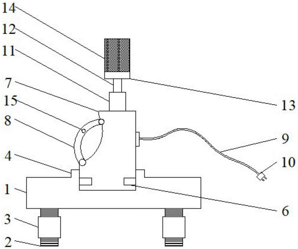
Mould internal surface processingequipment that polishes
Technical Field
The utility model relates to a mould processingequipment field of polishing particularly, relates to a mould internal surface processingequipment that polishes.
Background
In the industrial production of grinding tools, many are cold stamping dies, the dies are easy to heat during production, scrap iron stuck to plates is adhered to the surfaces and edges of the dies after each batch of production, the surfaces of the dies need to be maintained after production, the manual maintenance is carried out for a long time, only one piece of sand paper can be divided into 4 small pieces, and therefore the consumption of the sand paper is severe. The flatness of a palm which is polished by holding sand paper by hands is poor, the unevenness phenomenon is generated on the inner surface or the surface of an external covering part mould after long-time polishing, the apparent quality is seriously influenced, and the hand can be hurt due to excessive slipping caused by force sometimes during polishing. Present generally tear into 4 little sandpaper with sand paper and take to polish the mould on hand in the same trade, but at this whole in-process, slightly unevenness to the mould is beaten easily, influences part apparent quality and maintenance efficiency not high, and grinding device is heavier, holds for a long time and is comparatively labourer, influences the effect of polishing.
An effective solution to the problems in the related art has not been proposed yet.
SUMMERY OF THE UTILITY MODEL
An object of the utility model is to provide a surface finish machining device in mould to solve the problem that proposes among the above-mentioned background art.
In order to achieve the above object, the utility model provides a following technical scheme: a polishing device for the inner surface of a mould comprises a fixed plate, a polishing seat, a protective sleeve, a spring, a polishing cylinder and a polishing layer, threaded rods are arranged at four corners of the bottom of the fixed plate, threaded sleeves are sleeved on the threaded rods, the fixing plate is provided with a groove, the groove is internally provided with an opposite spring buckle, the groove is provided with a fixing sleeve communicated with the groove, a mounting seat is clamped in the groove, the polishing seat is fixedly connected on the mounting seat, a handle is arranged on one side of the polishing seat, the polishing seat is also internally provided with a driving motor, the protective sleeve is fixedly arranged at the middle part of the top end of the polishing seat, one end of the spring is connected with the protective sleeve through a bearing, the other end of the spring is clamped with the polishing barrel through a bayonet, the polishing barrel is of a cylinder structure with a closed lower end, and the outer wall and the inner wall of the polishing barrel are both provided with the frosting layer.
Furthermore, the polishing seat is connected with a power plug through a power line.
Further, a power switch is arranged on the handle.
Furthermore, power plug, power cord, switch and driving motor electricity in proper order are connected, and the mount pad both sides are provided with relative hole, the hole with the snak link joint.
Further, the driving motor is a variable frequency motor.
Furthermore, the power switch is a switch capable of adjusting the rotating speed of the driving motor.
Compared with the prior art, the utility model discloses following beneficial effect has:
(1) the utility model provides a pair of mould internal surface processingequipment that polishes is provided with the mounting panel, when taking up grinding device for a long time, and is great to physical demands, can with the grinding device joint in the recess, will treat that the apparatus of polishing is close to the dull polish layer and polish, and the fixed plate bottom is provided with the threaded rod, and the threaded rod cover has the thread bush, and the accessible rotates the level that the thread bush adjusted the fixed plate for polish more meticulously stably.
(2) The utility model provides a pair of processing device polishes in mould internal surface, mould grinding device can carry out effectual maintenance to the grinding apparatus internal and external surface of multiple structures such as drum, cylinder, plane, cambered surface, edge, reduces the finger and with the bruising between the mould, improves work efficiency, practices thrift the cost, easy operation.
Drawings
In order to more clearly illustrate the embodiments of the present invention or the technical solutions in the prior art, the drawings required to be used in the embodiments will be briefly described below, and it is obvious that the drawings in the following description are only some embodiments of the present invention, and for those skilled in the art, other drawings can be obtained according to these drawings without creative efforts.
Fig. 1 is a schematic structural view of a device for polishing and processing an inner surface of a mold according to an embodiment of the present invention;
fig. 2 is a schematic structural view of a polishing device for the inner surface of a mold according to an embodiment of the present invention;
fig. 3 is a schematic structural diagram of a fixing plate of the device for polishing and processing the inner surface of a mold according to the embodiment of the present invention.
Reference numerals:
1. a fixing plate; 2. a threaded rod; 3. a threaded sleeve; 4. fixing a sleeve; 5. a groove; 6. a spring buckle; 7. Polishing the base; 701. a mounting seat; 702. an aperture; 8. a handle; 9. a power line; 10. a power plug; 11. A protective sleeve; 12. a spring; 13. polishing the barrel; 14. sanding layer; 15. and a power switch.
Detailed Description
The technical solution in the embodiments of the present invention will be clearly and completely described below with reference to the drawings in the embodiments of the present invention, and it is obvious that the described embodiments are only some embodiments of the present invention, rather than all embodiments, and all other embodiments obtained by a person of ordinary skill in the art without creative work belong to the protection scope of the present invention based on the embodiments of the present invention.
In the description of the present invention, it should be noted that the terms "top", "bottom", "one side", "the other side", "front", "back", "middle part", "inside", "top", "bottom", etc. indicate the orientation or positional relationship based on the orientation or positional relationship shown in the drawings, which is only for the convenience of description and simplification of the description, but does not indicate or imply that the device or element referred to must have a specific orientation, be constructed in a specific orientation, and be operated, and thus, should not be construed as limiting the present invention; the terms "first," "second," and "third" are used for descriptive purposes only and are not to be construed as indicating or implying relative importance; furthermore, unless expressly stated or limited otherwise, the terms "mounted," "connected," and "connected" are to be construed broadly, as they may be fixedly connected, detachably connected, or integrally connected, for example; can be mechanically or electrically connected; they may be connected directly or indirectly through intervening media, or they may be interconnected between two elements. The specific meaning of the above terms in the present invention can be understood in specific cases to those skilled in the art.
Referring to fig. 1-3, a polishing device for inner surface of a mold according to an embodiment of the present invention comprises a fixing plate 1, a polishing seat 7, a protecting cover 11, a spring 12, a polishing barrel 13 and a polishing layer 14, wherein four corners of the bottom of the fixing plate 1 are all provided with threaded rods 2, the threaded rods 2 are sleeved with threaded sleeves 3, the fixing plate 1 is provided with a groove 5, the groove 5 is internally provided with a corresponding spring fastener 6, the groove 5 is provided with a fixing sleeve 4 communicated with the groove, the groove 5 is internally connected with a mounting seat 701, the mounting seat 701 is fixedly connected with the polishing seat 7, one side of the polishing seat 7 is provided with a handle 8, the polishing seat 7 is internally provided with a driving motor, the protecting cover 11 is fixedly arranged at the middle part of the top end of the polishing seat 7, one end of the spring 12 is connected with the protecting cover 11 through a bearing, the other end is connected with the polishing barrel 13, and the outer wall and the inner wall of the grinding cylinder 13 are both provided with a grinding layer 14.
Through the above technical scheme of the utility model, seat 7 of polishing is connected with power plug 10 through power cord 9.
Through the above technical scheme of the utility model, be provided with switch 15 on the handle 8.
Through the above technical scheme of the utility model, power plug 10, power cord 9, switch 15 and driving motor electricity in proper order are connected, and mount pad 701 both sides are provided with relative hole 702, hole 702 and 6 joints of snak link.
Through the above technical scheme of the utility model, driving motor is inverter motor, and accessible switch 15 adjusts different rotational speeds and polishes the surface of difference.
Through the above technical scheme of the utility model, switch 15 is the switch of adjustable driving motor rotational speed.
When specifically using, can be with the rotatory joint of grinding device in recess 5, snak link 6 supports in hole 702, adjusts 1 horizontal position of fixed plate through thread bush 3, and switch on opens switch 15, polishes the mould, does to change and gets grinding device, holds handle 8, polishes convenient and practical to mould die body position.
Finally, it should be noted that: although the present invention has been described in detail with reference to the foregoing embodiments, it will be apparent to those skilled in the art that modifications may be made to the embodiments described in the foregoing embodiments, or equivalents may be substituted for elements thereof. Any modification, equivalent replacement, or improvement made within the spirit and principle of the present invention should be included in the protection scope of the present invention.