Stamping equipment is used in auto-parts production and processing
Technical Field
The utility model relates to an auto-parts processing equipment technical field specifically is a stamping equipment is used in auto-parts production and processing.
Background
Stamping is a forming method in which a press and a die are used to apply external force to a plate, a strip, a pipe, a profile, etc. to cause plastic deformation or separation, thereby obtaining a workpiece of a desired shape and size. The stamping and forging are the same as plastic working, and are called forging and pressing together. The stamped blanks are mainly hot and cold rolled steel sheets and strips. In the world, 60-70% of steel materials are plates, and most of the plates are punched to form finished products. The body, chassis, oil tank, radiator sheet, boiler steam drum, shell of container, iron core silicon steel sheet of motor and electric appliance are all made by punching. There are also a large number of stamped parts in products such as instruments, household appliances, bicycles, office machines, and household utensils.
Automobile parts often need make it shaping to its punching press in the production and processing process, and the fixed effect of centre gripping of current stamping device to the work piece is relatively poor, and in the punching press process, the accessory easily takes place the skew, influences the machining precision, and in the punching press process of work piece simultaneously, often need adjust the punching press position, need to the work piece centre gripping location again, it is comparatively loaded down with trivial details, it is inconvenient to use. Therefore, the stamping equipment for the production and processing of the automobile parts has a good clamping and fixing effect on the workpieces, can improve the processing precision, can adjust the stamping position and does not need to clamp and position the workpieces again.
SUMMERY OF THE UTILITY MODEL
An object of the utility model is to provide a stamping equipment is used in auto-parts production and processing to solve the problem that proposes among the above-mentioned background art.
In order to achieve the above object, the utility model provides a following technical scheme:
the stamping equipment for producing and processing the automobile accessories comprises a base, wherein two sides above the base are respectively fixed with an upright post, top ends of the two upright posts are respectively fixed with a top beam, and a stamping device is arranged in the middle of the top beam; a sliding platform is connected to the middle position of the top of the base in a sliding manner, and a fixing device is arranged above the sliding platform;
the middle position of the top of the sliding platform is rotatably connected with a rotating platform through a rotating shaft, and one end of the rotating shaft, which is far away from the rotating platform, is rotatably connected to the inner wall of the bottom of the sliding platform; a driven bevel gear is fixed outside the rotating shaft; a first motor is installed on one side inside the sliding platform, a driving bevel gear is fixed at one end of an output shaft of the first motor, and the driving bevel gear is in meshing transmission with a driven bevel gear; the rear portion of the base is provided with a second motor, one end of an output shaft of the second motor is fixed with a screw rod, a threaded sleeve is sleeved on an external thread of the screw rod, the top of the threaded sleeve is fixedly connected with the bottom of the sliding platform, and the bottom of the threaded sleeve is slidably connected with the inner wall of the bottom of the base.
As a further aspect of the present invention: the stamping device comprises an oil cylinder, and the oil cylinder is arranged in the middle above the top beam; and a pushing block is arranged below the oil cylinder and penetrates through the inner wall of the top beam to extend to the lower part of the top beam.
As a further aspect of the present invention: a stamping block is fixed at the bottom of the pushing block, and connecting rods are fixed on two sides of the exterior of the stamping block; and one side of the outside of the two connecting rods is provided with a telescopic rod.
As a further aspect of the present invention: one end of each of the two telescopic rods is fixedly connected with the bottom of the top beam; and one ends of the two telescopic rods, which are far away from the top beam, are respectively and fixedly connected with one ends of the connecting rods at the corresponding positions.
As a further aspect of the present invention: the fixing device comprises a three-jaw chuck which is fixed above the rotating platform.
As a further aspect of the present invention: fixed arms are fixed on two sides of the outer portion of the three-jaw chuck, and one ends of the fixed arms are rotatably connected with rotating jaws.
As a further aspect of the present invention: the inside one side that is close to two fixed arms of three-jaw chuck all installs the third motor, two the one end of third motor output shaft all passes through the haulage rope and corresponds the one end fixed connection of the rotatory claw pivot of position.
As a further aspect of the present invention: and a processing platform is elastically connected above the three-jaw chuck through a plurality of elastic supports.
Compared with the prior art, the beneficial effects of the utility model are as follows:
1. the two third motors are started, the two rotating claws are rotated to enable the two rotating claws to clamp two ends of a workpiece, the workpiece is clamped and fixed on the machining platform, the workpiece fixing effect is good, the workpiece is not easy to deviate during machining, and the machining precision is improved;
2. the second motor is started, the screw rod is rotated, and the screw sleeve is matched with the sliding platform for use, so that the sliding platform is pushed out to one side along a sliding rail arranged on the base, and a workpiece is convenient to take and unload;
3. the first motor is started, the rotating platform and the workpiece fixed above the rotating platform are rotated, the machining position of the workpiece is adjusted, the workpiece does not need to be clamped again, and the use is convenient.
Drawings
Fig. 1 is a front view structure diagram of the present invention.
Fig. 2 is a front view of the connection between the base and the sliding platform of the present invention.
Fig. 3 is a side view of the connection between the base and the sliding platform of the present invention.
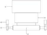
Fig. 4 is a schematic structural diagram of the middle stamping device of the present invention.
Fig. 5 is a schematic structural view of the middle fixing device of the present invention.
Notations for reference numerals: 1-base, 2-upright post, 3-top beam, 4-punching device, 5-fixing device, 6-sliding platform, 7-rotating platform, 8-first motor, 9-thread sleeve, 10-screw, 11-driven bevel gear, 12-driving bevel gear, 13-rotating shaft, 14-second motor, 41-oil cylinder, 42-telescopic rod, 43-connecting rod, 44-punching block, 45-pushing block, 51-three-jaw chuck, 52-third motor, 53-fixing arm, 54-rotating jaw, 55-elastic support and 56-processing platform.
Detailed Description
The present invention will be described in detail with reference to the following embodiments, wherein like or similar elements are designated by like reference numerals throughout the drawings or description, and wherein the shape, thickness or height of the various elements may be expanded or reduced in practical applications. The embodiments of the present invention are provided only for illustration, and not for limiting the scope of the present invention. Any obvious and obvious modifications or alterations to the present invention can be made without departing from the spirit and scope of the present invention.
Example 1
Referring to fig. 1 to 3, in an embodiment of the present invention, a stamping apparatus for manufacturing and processing automobile accessories includes a base 1, wherein two sides above the base 1 are both fixed with columns 2, top ends of the two columns 2 are fixed with top beams 3, and a stamping device 4 is arranged in a middle position of the top beams 3; a sliding platform 6 is connected to the middle position of the top of the base 1 in a sliding manner, and a fixing device 5 is arranged above the sliding platform 6;
the middle position of the top of the sliding platform 6 is rotatably connected with a rotating platform 7 through a rotating shaft 13, and one end of the rotating shaft 13, which is far away from the rotating platform 7, is rotatably connected to the inner wall of the bottom of the sliding platform 6; a driven bevel gear 11 is fixed outside the rotating shaft 13; a first motor 8 is installed on one side inside the sliding platform 6, a driving bevel gear 12 is fixed at one end of an output shaft of the first motor 8, and the driving bevel gear 12 is in meshing transmission with a driven bevel gear 11; the rear portion of the base 1 is provided with a second motor 14, one end of an output shaft of the second motor 14 is fixed with a screw rod 10, a threaded sleeve 9 is sleeved on an external thread of the screw rod 10, the top of the threaded sleeve 9 is fixedly connected with the bottom of the sliding platform 6, and the bottom of the threaded sleeve 9 is slidably connected with the inner wall of the bottom of the base 1.
Example 2
Referring to fig. 4 to 5, on the basis of embodiment 1, the stamping device 4 includes an oil cylinder 41, and the oil cylinder 41 is installed at a middle position above the top beam 3; a pushing block 45 is arranged below the oil cylinder 41, and the pushing block 45 penetrates through the inner wall of the top beam 3 and extends to the position below the top beam 3; a punching block 44 is fixed at the bottom of the pushing block 45, and connecting rods 43 are fixed on two sides of the outside of the punching block 44; one side outside each of the two connecting rods 43 is provided with a telescopic rod 42, and one end of each of the two telescopic rods 42 is fixedly connected with the bottom of the top beam 3; one ends of the two telescopic rods 42 far away from the top beam 3 are respectively fixedly connected with one ends of the connecting rods 43 at corresponding positions;
the fixing device 5 comprises a three-jaw chuck 51, and the three-jaw chuck 51 is fixed above the rotating platform 7; fixed arms 53 are fixed on two sides of the outer part of the three-jaw chuck 51, and one ends of the two fixed arms 53 are rotatably connected with rotating jaws 54; third motors 52 are respectively arranged at one sides of the three-jaw chuck 51 close to the two fixed arms 53, and one ends of output shafts of the two third motors 52 are respectively fixedly connected with one ends of rotating shafts of the rotating jaws 54 at corresponding positions through traction ropes; a processing platform 56 is elastically connected above the three-jaw chuck 51 through a plurality of elastic supports 55.
When the device is used, a workpiece to be machined is placed on the machining platform 56, the two third motors 52 are started, the two rotating claws 54 are rotated, the two rotating claws 54 clamp two ends of the workpiece, and the workpiece is clamped and fixed on the machining platform 56; starting the stamping device 4, and stamping the workpiece by matching the oil cylinder 41, the pushing block 45, the stamping block 44 and the like; after the machining is finished, starting the second motor 14, rotating the screw rod 10, pushing the sliding platform 6 out to one side along a sliding rail arranged on the base 1 through the matching use of the threaded sleeve 9 and the sliding platform 6, and taking down the workpiece; in the process of processing the workpiece, the first motor 8 can be started to rotate the rotating platform 7 and the workpiece fixed above the rotating platform 7, the processing position of the workpiece is adjusted, the workpiece does not need to be repositioned and clamped, and the use is convenient.
It is obvious to a person skilled in the art that the invention is not restricted to details of the above-described exemplary embodiments, but that it can be implemented in other specific forms without departing from the spirit or essential characteristics of the invention. The present embodiments are therefore to be considered in all respects as illustrative and not restrictive, the scope of the invention being indicated by the appended claims rather than by the foregoing description, and all changes which come within the meaning and range of equivalency of the claims are therefore intended to be embraced therein. Any reference sign in a claim should not be construed as limiting the claim concerned.
Furthermore, it should be understood that although the present description refers to embodiments, not every embodiment may contain only a single embodiment, and such description is for clarity only, and those skilled in the art should integrate the description, and the embodiments may be combined as appropriate to form other embodiments understood by those skilled in the art.