CN213085347U - Synchronous lifting seat base used for automobile repair based on large special vehicle - Google Patents
Synchronous lifting seat base used for automobile repair based on large special vehicle Download PDFInfo
- Publication number
- CN213085347U CN213085347U CN202022052512.6U CN202022052512U CN213085347U CN 213085347 U CN213085347 U CN 213085347U CN 202022052512 U CN202022052512 U CN 202022052512U CN 213085347 U CN213085347 U CN 213085347U
- Authority
- CN
- China
- Prior art keywords
- support
- main
- special vehicle
- face
- main body
- Prior art date
- Legal status (The legal status is an assumption and is not a legal conclusion. Google has not performed a legal analysis and makes no representation as to the accuracy of the status listed.)
- Expired - Fee Related
Links
- 230000001360 synchronised effect Effects 0.000 title claims abstract description 14
- 230000008439 repair process Effects 0.000 title claims abstract description 11
- 230000007246 mechanism Effects 0.000 claims abstract description 61
- 230000035939 shock Effects 0.000 claims description 18
- 238000009434 installation Methods 0.000 claims description 11
- 239000006096 absorbing agent Substances 0.000 claims description 10
- 230000005540 biological transmission Effects 0.000 claims description 8
- 230000008878 coupling Effects 0.000 claims 1
- 238000010168 coupling process Methods 0.000 claims 1
- 238000005859 coupling reaction Methods 0.000 claims 1
- 238000012423 maintenance Methods 0.000 abstract description 6
- 230000000694 effects Effects 0.000 abstract description 3
- 230000005484 gravity Effects 0.000 abstract description 3
- 238000010521 absorption reaction Methods 0.000 description 4
- 238000012986 modification Methods 0.000 description 2
- 230000004048 modification Effects 0.000 description 2
- 208000027418 Wounds and injury Diseases 0.000 description 1
- 230000009286 beneficial effect Effects 0.000 description 1
- 230000006378 damage Effects 0.000 description 1
- 230000007547 defect Effects 0.000 description 1
- 238000010586 diagram Methods 0.000 description 1
- 238000006073 displacement reaction Methods 0.000 description 1
- 230000006872 improvement Effects 0.000 description 1
- 208000014674 injury Diseases 0.000 description 1
- 238000010008 shearing Methods 0.000 description 1
- 238000005303 weighing Methods 0.000 description 1
Images




Landscapes
- Vehicle Cleaning, Maintenance, Repair, Refitting, And Outriggers (AREA)
Abstract
The utility model provides a synchronous lifting seat base used for automobile repair based on large-scale special vehicle, relating to the technical field of automobile repair of special vehicles, solving the problem that the existing special vehicle lifting device can not effectively limit the special vehicle when in maintenance, thereby possibly causing the special vehicle to overturn due to unstable gravity center, and the side edge of the special vehicle can not be effectively protected against falling, so that the potential safety hazard can be left, the anti-falling device comprises a wheel base adjusting mechanism, the axle distance adjusting mechanism is provided with two positions, in the utility model, when the scissor fork rod slides and rises, the axle distance adjusting mechanisms at the two positions can be lifted, the design can replace the problems that the traditional four-point support type lifting mechanism can bear lower weight and cannot carry out stable lifting operation on the special vehicle, so that the effect of stably lifting the special vehicle is achieved more stably.
Description
Technical Field
The utility model belongs to the technical field of special type vehicle vapour is repaiied, more specifically says, in particular to synchronous promotion seat platform based on large-scale special type vehicle vapour is repaiied and is used.
Background
The special vehicle refers to a vehicle with the external dimension, the weight and the like exceeding the design vehicle limit and special purposes, is specially made or specially modified and is provided with fixed device equipment, the main function is not used for a motor vehicle carrying people or goods, the special vehicle generally has a special mark or a special vehicle type, and refers to a vehicle which bears special service, hangs a special vehicle number plate, and is provided with an alarm and a mark lamp, such as an ambulance, a fire truck, a police car, an engineering rescue vehicle, a military supervision vehicle and the like;
the special vehicle is limited by the problems of large volume and non-centered gravity center, so that the traditional lifting device cannot be used for lifting when the chassis of the special vehicle is repaired.
Therefore, in view of the above, research and improvement are made for the existing structure and defects, and a synchronous lifting seat base used for automobile repair of a large special vehicle is provided, so as to achieve the purpose of higher practical value.
SUMMERY OF THE UTILITY MODEL
In order to solve the technical problem, the utility model provides a synchronous promotion seat post based on large-scale special vehicle vapour is repaiied and is used to solve current special vehicle lifting device and can't carry out effectual limiting displacement to the special vehicle when maintaining, consequently can cause the special vehicle to overturn because of the focus is unstable, and can't carry out effectual protection of preventing weighing down to the side of special vehicle, consequently can leave the problem of potential safety hazard.
The utility model discloses purpose and efficiency based on the synchronous promotion seat platform that large-scale special vehicle vapour was repaiied and is used reach by following specific technological means:
a synchronous lifting seat platform used for automobile repair based on large special vehicles comprises a wheel base adjusting mechanism, a first support, a second support and a side protection anti-falling mechanism, wherein the wheel base adjusting mechanism is provided with two positions, and the two positions of the wheel base adjusting mechanism are fixedly connected to the top end face position of a lifting mechanism; the first support and the second support are both provided with two positions, and the first support and the second support at each position are both arranged at the internal positions of the wheel base adjusting mechanism in an up-and-down meshing transmission manner; the two second supports are respectively and rotatably connected to the left end face and the right end face of the two wheelbase adjusting mechanisms; the side guard anti-falling mechanism is provided with two positions, and the two side guard anti-falling mechanisms are respectively and fixedly connected to the left end surface and the right end surface of the two wheelbase adjusting mechanisms; the side guard anti-falling mechanism comprises a rotating block, a main guard plate, a shock absorber and a shock absorption guard plate, wherein the main guard plate is provided with two parts, the two main guard plates are connected to the inner side of the rotating block in a shaft mode, the main guard plate is connected to the right end of the two main guard plates through the two shock absorbers in an elastic mode, and the two main guard plates, the shock absorber and the shock absorption guard plate are connected to the left end face and the right end face of the main support through the rotating block in a fixed mode in the installation state.
Further, lifting mechanism is including hydraulic base, positioning disk and scissors fork pole, hydraulic base is equipped with two altogether, and the inside of two hydraulic base all installs the positioning disk, scissors fork pole installs the inside position at hydraulic base, and scissors fork pole and positioning disk looks sliding connection.
Furthermore, wheel base guiding mechanism is including main bearing, hand wheel screw rod and gear, the hand wheel screw rod rotates to be connected in the left end face central point of main bearing and puts, and the hand wheel screw rod passes main bearing to the right-hand member face fixedly connected with gear of hand wheel screw rod, main bearing fixed connection is in the top end face position of scissors fork pole under the installation condition.
Furthermore, first support is including main part A, rack A and race, main part A's preceding terminal surface fixedly connected with rack A, the race is seted up in main part A's top face right side position, and main part A pegs graft in the inside position of main support under the installation to through rack A meshing transmission directly over the position of gear.
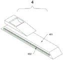
Furthermore, the second support comprises a main body B, a rack B, a hydraulic column and an auxiliary support, the rack B is fixedly connected to the front end face of the main body B, the hydraulic column is provided with two positions, the top end faces of the two hydraulic columns are fixedly connected with the auxiliary support, a wheel groove is formed in the auxiliary support, and the main body B is in meshed transmission with the gear through the rack B under the installation state.
Compared with the prior art, the utility model discloses following beneficial effect has:
in the utility model, when the scissor rod is lifted in a sliding way, two wheelbase adjusting mechanisms can be lifted, the design can replace the problems that the traditional four-point support type lifting mechanism can bear lower weight and can not lift a special vehicle stably, so as to achieve the effect of stably lifting the special vehicle more stably, on the other hand, according to the difference of wheelbases of the special vehicle, the main body A in the first support and the main body B in the second support can be respectively ejected out from the main support through the meshing transmission of the rack A and the rack B with the gear by manually rotating the hand wheel screw in the wheelbase adjusting mechanism, then the tire of the vehicle can be placed at the inner position of the wheel groove, the special vehicle can be stabilized and limited, so as to achieve the purpose of more practicality, moreover, the main guard plates in the two side protection anti-falling mechanisms can be rotated around the rotating block after the special vehicle is lifted, the side of the special vehicle can be maintained and operated by screwing the bolt after being effectively protected and operated, and the design can effectively protect maintenance personnel.
Additional advantages, objects, and features of the invention will be set forth in part in the description which follows and in part will become apparent to those having ordinary skill in the art upon examination of the following or may be learned from practice of the invention.
Drawings
Fig. 1 is a schematic side view of the present invention.
Fig. 2 is a schematic view of the structure of the present invention.
Fig. 3 is a schematic top view of the present invention.
Fig. 4 is a schematic structural diagram of the lifting mechanism of the present invention.
Fig. 5 is a schematic structural view of the wheel base adjusting mechanism of the present invention.
Fig. 6 is a schematic view of the first support structure of the present invention.
Fig. 7 is a schematic side view of the second support according to the present invention.
Fig. 8 is a schematic front view of the second support according to the present invention.
Fig. 9 is a schematic structural view of the side guard anti-falling mechanism of the utility model.
In the drawings, the corresponding relationship between the component names and the reference numbers is as follows:
1. a lifting mechanism; 101. a hydraulic base; 102. a guide plate; 103. shearing a fork rod; 2. a wheel base adjusting mechanism; 201. a main support; 202. a hand wheel screw; 203. a gear; 3. a first support; 301. a main body A; 302. a rack A; 303. a wheel groove; 4. a second support; 401. a main body B; 402. a rack B; 403. a hydraulic column; 404. a secondary support; 5. a side protection anti-falling mechanism; 501. rotating the block; 502. a main guard plate; 503. a shock absorber; 504. shock attenuation backplate.
Detailed Description
The following describes embodiments of the present invention in further detail with reference to the accompanying drawings and examples. The following examples are intended to illustrate the invention, but are not intended to limit the scope of the invention.
In the description of the present invention, "a plurality" means two or more unless otherwise specified; the terms "upper", "lower", "left", "right", "inner", "outer", "front", "rear", "head", "tail", and the like indicate orientations or positional relationships based on the orientations or positional relationships shown in the drawings, and are merely for convenience of description and simplicity of description, and do not indicate or imply that the device or element being referred to must have a particular orientation, be constructed and operated in a particular orientation, and thus, should not be construed as limiting the present invention. Furthermore, the terms "first," "second," "third," and the like are used for descriptive purposes only and are not to be construed as indicating or implying relative importance.
In the description of the present invention, it is to be noted that, unless otherwise explicitly specified or limited, the terms "connected" and "connected" are to be interpreted broadly, and may be, for example, fixedly connected, detachably connected, or integrally connected; can be mechanically or electrically connected; may be directly connected or indirectly connected through an intermediate. The specific meaning of the above terms in the present invention can be understood in specific cases to those skilled in the art.
Example (b):
as shown in figures 1 to 9:
the utility model provides a synchronous lifting seat platform used for automobile repair based on a large-scale special vehicle, which comprises a wheel base adjusting mechanism 2, a first support 3, a second support 4 and a side protection anti-falling mechanism 5, wherein the wheel base adjusting mechanism 2 is provided with two parts, and the two wheel base adjusting mechanisms 2 are fixedly connected with the top end surface position of a lifting mechanism 1; the first support 3 and the second support 4 are both provided with two positions, and the first support 3 and the second support 4 at each position are both arranged at the inner positions of the wheel base adjusting mechanism 2 in an up-and-down meshing transmission manner; the second support 4 is provided with two positions, and the two second supports 4 are respectively and rotatably connected to the left end face and the right end face of the two wheelbase adjusting mechanisms 2; the side protection anti-falling mechanisms 5 are arranged at two positions, and the two side protection anti-falling mechanisms 5 are respectively and fixedly connected to the left end face and the right end face of the two wheelbase adjusting mechanisms 2; the side guard anti-falling mechanism 5 comprises a rotating block 501, a main guard plate 502, a shock absorber 503 and a shock absorption guard plate 504, wherein the main guard plate 502 is provided with two positions, the two main guard plates 502 are connected to the inner side of the rotating block 501 in a shaft mode, the main guard plate 502 is elastically connected to the right end positions of the two main guard plates 502 through the two shock absorbers 503, and the two main guard plates 502, the shock absorber 503 and the shock absorption guard plate 504 are fixedly connected to the left end face and the right end face of the main support 201 through the rotating block 501 in the installation state.
Wherein, lifting mechanism 1 is including hydraulic pressure base 101, positioning disk 102 and scissors pole 103, and hydraulic pressure base 101 is equipped with two altogether, and two hydraulic pressure base 101's inside all installs positioning disk 102, and scissors pole 103 installs the inside position at hydraulic pressure base 101, and scissors pole 103 and positioning disk 102 looks sliding connection.
The wheel base adjusting mechanism 2 comprises a main support 201, a hand wheel screw 202 and a gear 203, the hand wheel screw 202 is rotatably connected to the center of the left end face of the main support 201, the hand wheel screw 202 penetrates through the main support 201, the gear 203 is fixedly connected to the right end face of the hand wheel screw 202, and the main support 201 is fixedly connected to the top end face of the scissor rod 103 in an installation state.
Wherein, first support 3 is including main part A301, rack A302 and race 303, the preceding terminal surface fixedly connected with rack A302 of main part A301, race 303 sets up the top face right side position at main part A301, main part A301 pegs graft in the inside position of main support 201 under the mounted state, and through rack A302 meshing transmission in gear 203 directly over the position, can place the inside position of race 303 with the tire of vehicle, can stabilize spacing with the special type vehicle, in order to reach more practical purpose.
The second support 4 comprises a main body B401, a rack B402, a hydraulic column 403 and an auxiliary support 404, the front end face of the main body B401 is fixedly connected with the rack B402, the hydraulic column 403 is provided with two positions, the top end faces of the two hydraulic columns 403 are fixedly connected with the auxiliary support 404, the auxiliary support 404 is internally provided with a wheel groove 303, and the main body B401 is meshed with and driven under the gear 203 through the rack B402 in the installation state.
The specific use mode and function of the embodiment are as follows:
when the lifting mechanism is used, the lifting mechanism 1 is firstly placed in the ground for fixing, after the fixing is finished, the hydraulic base 101 in the lifting mechanism 1 is started to slide and lift the scissor rod 103 along the guide disc 102, and when the scissor rod 103 slides and rises, the two-position wheelbase adjusting mechanism 2 can rise, so that the design can replace the problems that the traditional four-point support type lifting mechanism can bear lower weight and cannot perform stable lifting operation on a special vehicle, and the effect of stably lifting the special vehicle is achieved;
on the other hand, according to different wheel bases of special vehicles, the hand wheel screw 202 in the wheel base adjusting mechanism 2 is manually rotated to enable the main body A301 in the first support 3 and the main body B401 in the second support 4 to respectively eject the main body A301 and the main body B401 from the interior of the main support 201 through the meshing transmission of the rack A302, the rack B402 and the gear 203, then tires of the vehicles can be placed in the inner positions of the wheel grooves 303, and the special vehicles can be stably limited, so that the purpose of being more practical is achieved;
furthermore, in order to prevent the problem that the special vehicle falls from the lifting mechanism 1 to cause injury to maintenance personnel due to unstable gravity center of the special vehicle or shock generated during maintenance when the special vehicle is lifted, the main guard plates 502 in the two side protection anti-falling mechanisms 5 can be rotated around the rotating block 501 after the special vehicle is lifted until the side edges of the special vehicle can be effectively protected and then screwed through bolts to carry out maintenance operation, and the design can effectively protect the maintenance personnel.
The embodiments of the present invention have been presented for purposes of illustration and description, and are not intended to be exhaustive or limited to the invention in the form disclosed. Many modifications and variations will be apparent to those of ordinary skill in the art. The embodiment was chosen and described in order to best explain the principles of the invention and the practical application, and to enable others of ordinary skill in the art to understand the invention for various embodiments with various modifications as are suited to the particular use contemplated.
Claims (5)
1. The utility model provides a synchronous promotion seat stand based on use is repaiied to large-scale special type vehicle vapour which characterized in that: the device comprises a wheelbase adjusting mechanism (2), a first support (3), a second support (4) and a side protection anti-falling mechanism (5), wherein the wheelbase adjusting mechanism (2) is provided with two positions, and the two wheelbase adjusting mechanisms (2) are fixedly connected to the top end face of the lifting mechanism (1); the first support (3) and the second support (4) are respectively provided with two positions, and the first support (3) and the second support (4) at each position are vertically arranged and meshed with each other to be driven at the inner position of the wheel base adjusting mechanism (2); the second supports (4) are provided with two positions, and the two second supports (4) are respectively and rotatably connected to the left end face and the right end face of the two wheelbase adjusting mechanisms (2); the side guard anti-falling mechanisms (5) are arranged at two positions, and the two side guard anti-falling mechanisms (5) are respectively and fixedly connected to the left end face and the right end face of the two wheelbase adjusting mechanisms (2); the side guard anti-falling mechanism (5) is including changeing piece (501), main backplate (502), shock absorber (503) and shock attenuation backplate (504), main backplate (502) are equipped with two places altogether, and two main backplate (502) all the coupling in the inboard position of changeing piece (501), main backplate (502) are through two shock absorbers (503) elastic connection at the right-hand member position of two main backplate (502), and two main backplate (502), shock absorber (503) and shock attenuation backplate (504) are all through changeing piece (501) fixed connection both ends face position about main support (201) under the installation status.
2. The synchronous lifting seat base used for the automobile repair of the large special vehicle as claimed in claim 1, wherein: lifting mechanism (1) is including hydraulic pressure base (101), deflector (102) and scissor rod (103), hydraulic pressure base (101) are equipped with two altogether, and deflector (102) are all installed to the inside of two hydraulic pressure bases (101), scissor rod (103) are installed in the inside position of hydraulic pressure base (101), and scissor rod (103) and deflector (102) looks sliding connection.
3. The synchronous lifting seat base used for the automobile repair of the large special vehicle as claimed in claim 1, wherein: wheel base guiding mechanism (2) is including main support (201), hand wheel screw rod (202) and gear (203), hand wheel screw rod (202) rotate to be connected the left end face central point of main support (201) and hand wheel screw rod (202) pass main support (201) to the right-hand member face fixedly connected with gear (203) of hand wheel screw rod (202), main support (201) fixed connection is in the top terminal surface position of scissors fork arm (103) under the installation condition.
4. The synchronous lifting seat base used for the automobile repair of the large special vehicle as claimed in claim 1, wherein: the first support (3) comprises a main body A (301), a rack A (302) and a wheel groove (303), the front end face of the main body A (301) is fixedly connected with the rack A (302), the wheel groove (303) is arranged at the right side position of the top end face of the main body A (301), the main body A (301) is inserted into the inner position of the main support (201) in the installation state, and the main body A (301) is meshed with and transmitted to the position right above the gear (203) through the rack A (302).
5. The synchronous lifting seat base used for the automobile repair of the large special vehicle as claimed in claim 1, wherein: the second support (4) comprises a main body B (401), a rack B (402), a hydraulic column (403) and an auxiliary support (404), the rack B (402) is fixedly connected to the front end face of the main body B (401), the hydraulic column (403) is provided with two positions, the auxiliary support (404) is fixedly connected to the top end faces of the two hydraulic columns (403), a wheel groove (303) is formed in the auxiliary support (404), and the main body B (401) is in meshing transmission through the rack B (402) under the gear (203) in the installation state.
Priority Applications (1)
| Application Number | Priority Date | Filing Date | Title |
|---|---|---|---|
| CN202022052512.6U CN213085347U (en) | 2020-09-18 | 2020-09-18 | Synchronous lifting seat base used for automobile repair based on large special vehicle |
Applications Claiming Priority (1)
| Application Number | Priority Date | Filing Date | Title |
|---|---|---|---|
| CN202022052512.6U CN213085347U (en) | 2020-09-18 | 2020-09-18 | Synchronous lifting seat base used for automobile repair based on large special vehicle |
Publications (1)
| Publication Number | Publication Date |
|---|---|
| CN213085347U true CN213085347U (en) | 2021-04-30 |
Family
ID=75612403
Family Applications (1)
| Application Number | Title | Priority Date | Filing Date |
|---|---|---|---|
| CN202022052512.6U Expired - Fee Related CN213085347U (en) | 2020-09-18 | 2020-09-18 | Synchronous lifting seat base used for automobile repair based on large special vehicle |
Country Status (1)
| Country | Link |
|---|---|
| CN (1) | CN213085347U (en) |
Cited By (1)
| Publication number | Priority date | Publication date | Assignee | Title |
|---|---|---|---|---|
| CN113860212A (en) * | 2021-10-09 | 2021-12-31 | 黄燕 | A lifting device that vehicle processing antiskid that is used for car production line moves |
-
2020
- 2020-09-18 CN CN202022052512.6U patent/CN213085347U/en not_active Expired - Fee Related
Cited By (2)
| Publication number | Priority date | Publication date | Assignee | Title |
|---|---|---|---|---|
| CN113860212A (en) * | 2021-10-09 | 2021-12-31 | 黄燕 | A lifting device that vehicle processing antiskid that is used for car production line moves |
| CN113860212B (en) * | 2021-10-09 | 2023-12-22 | 黄燕 | A lifting device that is used for vehicle processing of car production line to prevent sliding |
Similar Documents
| Publication | Publication Date | Title |
|---|---|---|
| DE112014004921T5 (en) | System for rapid insertion and removal of a battery for vehicles | |
| CN103738885B (en) | A kind of electromagnetic type single-column movable hydraulic lifting machine | |
| US10974938B2 (en) | Vehicle lift assembly | |
| CN213112381U (en) | Automobile maintenance platform | |
| CN222157384U (en) | A heavy-duty anti-collision buffer vehicle | |
| CN203093829U (en) | Safety supporting device for cargo box of automobile | |
| CN218586245U (en) | Power battery pack with anti-loosening structure for installation | |
| CN217861220U (en) | Service creeper device for auto repair | |
| CN212222296U (en) | Multipurpose full-automatic automobile lifter | |
| CN212450449U (en) | Lifting device for vehicle detection | |
| CN216638782U (en) | Movable vehicle body lifting support | |
| CN117144827A (en) | Vehicle traffic height limiting device for road and bridge | |
| CN212609290U (en) | Auto repair elevating gear with insurance function | |
| CN215905791U (en) | Primary-secondary type four-column lifter | |
| CN209778195U (en) | Order-picking vehicle | |
| CN223852250U (en) | Anti-falling mechanism of lifting platform | |
| CN222781347U (en) | Piling car convenient to installation and maintenance | |
| CN218290323U (en) | Whole car elevating gear is used in new energy automobile maintenance | |
| CN217198092U (en) | A convenient road rescue wrecker | |
| CN220549033U (en) | Labor-saving safety support | |
| CN216580287U (en) | Wrecker device based on repair space | |
| CN207191018U (en) | A kind of fixing vehicle wheel jacking apparatus | |
| CN113003232B (en) | A safe handling turning device for large-scale machine part | |
| CN221370504U (en) | A standing riding lift with protective function | |
| CN222225873U (en) | Fork truck with prevent empting function |
Legal Events
| Date | Code | Title | Description |
|---|---|---|---|
| GR01 | Patent grant | ||
| GR01 | Patent grant | ||
| CF01 | Termination of patent right due to non-payment of annual fee |
Granted publication date: 20210430 |
|
| CF01 | Termination of patent right due to non-payment of annual fee |