CN213082216U - Injection mold with front mold slider and convenient for rear mold core pulling - Google Patents
Injection mold with front mold slider and convenient for rear mold core pulling Download PDFInfo
- Publication number
- CN213082216U CN213082216U CN202021749092.0U CN202021749092U CN213082216U CN 213082216 U CN213082216 U CN 213082216U CN 202021749092 U CN202021749092 U CN 202021749092U CN 213082216 U CN213082216 U CN 213082216U
- Authority
- CN
- China
- Prior art keywords
- insert
- mold
- slide block
- mould
- plate
- Prior art date
- Legal status (The legal status is an assumption and is not a legal conclusion. Google has not performed a legal analysis and makes no representation as to the accuracy of the status listed.)
- Active
Links
Images


Abstract
The utility model discloses an injection mould with a front mould slide block and convenient for a rear mould to loose core, which comprises a front mould component and a rear mould component, the front mold assembly comprises a hot runner plate and a molding plate, a group of slide block inserts and a front mold main insert are arranged in the molding plate, the hot runner plate is provided with a front mould auxiliary insert matched with the slide block insert, the rear mould assembly is provided with a rear mould main insert matched with the front mould main insert, the slide block insert is provided with a first cooling water path and a first water stop plate along the circumferential surface of the slide block insert, the front mold main insert is of a step-shaped structure with the center protruding upwards, and the circumferential surface of the bulge part is provided with a second cooling water path, the rear die assembly is also provided with a first rear die auxiliary insert and a second rear die auxiliary insert which extend into the rear die main insert, and a second cooling water path is arranged between the first rear die auxiliary insert and the second rear die auxiliary insert.
Description
Technical Field
The utility model relates to an injection mold with front mould slider and be convenient for back mould is loosed core belongs to injection mold technical field.
Background
The die is various dies and tools for obtaining required products by injection molding, blow molding, extrusion, die casting or forging forming, smelting, stamping and other methods in industrial production. In short, a mold is a tool used to shape an article, the tool being made up of various parts, and different molds being made up of different parts. The method realizes the processing of the appearance of the article mainly by changing the physical state of the formed material, and the article is called as 'industrial mother'.
In injection mold designs, multiple cavities with undercuts are often encountered. Some products are inclined ejector and slider, but a plurality of products that have the knot position of arranging, need loose core again have following several problem points:
1. in the existing sliding block structure, because a front die sliding block needs to be positioned, a front die core needs to be manufactured in the traditional method, so that the die arrangement is increased, and meanwhile, the front die core is not easy to cool;
2. the existing slide block insert is designed into an integral structure because the slide block is very thin, but the whole slide block can be replaced if the glue part of the slide block needs to be replaced, so that the cost is too high, and the cooling effect is not good;
3. the traditional design of the existing front mould sliding block is that a pressing strip is independently fixed on a forming plate, so that the sliding block moves under the fixation of the pressing strip and is not well positioned.
SUMMERY OF THE UTILITY MODEL
The utility model aims to solve the technical problem that an injection mold with front mould slider and be convenient for back mould is loosed core is provided, through with front mould main mold insert and slider fixed in the profiled sheeting of front mould subassembly, reduce the mould space of arranging, increase the cooling effect, utilize the drawing of patterns of oblique guide pillar and knot machine structure realization product simultaneously.
In order to solve the technical problem, the utility model discloses the technical scheme who adopts is:
an injection mold with a front mold slide block and convenient for core pulling of a rear mold comprises a front mold component and a rear mold component, the front mold assembly comprises a hot runner plate and a molding plate, a group of slide block inserts and a front mold main insert are arranged in the molding plate, the hot runner plate is provided with a front mould auxiliary insert matched with the slide block insert, the rear mould assembly is provided with a rear mould main insert matched with the front mould main insert, the slide block insert is provided with a first cooling water path and a first water stop plate along the circumferential surface of the slide block insert, the front mold main insert is of a step-shaped structure with the center protruding upwards, and the circumferential surface of the bulge part is provided with a second cooling water path, the rear die assembly is also provided with a first rear die auxiliary insert and a second rear die auxiliary insert which extend into the rear die main insert, and a second cooling water path is arranged between the first rear die auxiliary insert and the second rear die auxiliary insert.
The utility model provides an injection mold who just is convenient for back mould to loose core with front mould slider which characterized in that: the rear die assembly is further provided with a third rear die auxiliary insert extending into the second rear die auxiliary insert, the top of the third rear die auxiliary insert is provided with a cooling rod, and a third cooling water channel and a second water stop plate are arranged in the third rear die auxiliary insert below the cooling rod.
The utility model provides an injection mold who just is convenient for back mould to loose core with front mould slider which characterized in that: the slider mold insert is fixedly connected to the slider base, an inclined guide groove is formed in the slider base, and an inclined guide pillar inserted into the inclined guide groove is fixedly connected to the forming plate.
The utility model provides an injection mold who just is convenient for back mould to loose core with front mould slider which characterized in that: the forming plate is also fixedly connected with a limiting bolt with a head inserted into the hot runner plate, and the hot runner plate is provided with a limiting step surface corresponding to the insertion position of the limiting bolt.
The utility model provides an injection mold who just is convenient for back mould to loose core with front mould slider which characterized in that: the side of hot runner plate is provided with the knot machine limiting plate that can inwards move, the side of profiled sheeting is provided with and drives detain the first knot machine of the inwards movement of quick-witted limiting plate, the side of back mould subassembly is provided with and to articulate the second knot machine at detaining the quick-witted limiting plate.
The utility model provides an injection mold who just is convenient for back mould to loose core with front mould slider which characterized in that: before the limiting bolt moves to the limiting step surface, the first button machine pushes the button machine limiting plate to move towards the inner side of the forming plate, and the limitation of the second button machine is removed.
The utility model has the advantages that: through fixing front mould main mold insert and slider in the profiled sheeting of front mould subassembly, reduce the mould space of arranging, increase the cooling effect, utilize oblique guide pillar and knot machine structure to realize the drawing of patterns of product simultaneously.
Drawings
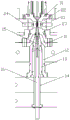
FIG. 1 is a schematic structural view of an injection mold with a front mold slide block and facilitating core pulling of a rear mold according to the present invention;
FIG. 2 is a schematic structural view of an injection molding portion of an injection mold with a front mold slide block and facilitating core pulling of a rear mold according to the present invention;
FIG. 3 is an enlarged schematic view of A of FIG. 1;
fig. 4 is an enlarged schematic view of B in fig. 1.
Detailed Description
The invention will be further described with reference to the accompanying drawings.
As shown in fig. 1-4, an injection mold with a front mold slide block and facilitating core pulling of a rear mold comprises a front mold assembly and a rear mold assembly 1, wherein the front mold assembly comprises a hot runner plate 2 and a forming plate 3, a set of slide block inserts 22 and a front mold main insert 23 are arranged in the forming plate 3, a front mold auxiliary insert 31 matched with the slide block inserts 22 is arranged on the hot runner plate 2, a rear mold main insert 11 matched with the front mold main insert 23 is arranged on the rear mold assembly 1, the slide block insert 22 is provided with a first cooling water path and a first water stop plate 24 along the circumferential surface thereof, the front mold main insert 23 is of a step-shaped structure with an upward convex center, a second cooling water path is arranged on the circumferential surface of a convex part, the rear mold assembly 1 is further provided with a first rear mold auxiliary insert 12 and a second rear mold auxiliary insert 13 extending into the rear mold main insert 11, and a second cooling water path is arranged between the first rear mold auxiliary insert 12 and the second rear mold auxiliary insert 13.
Through setting up front mould main insert 23 and slider insert 22 in the profiled sheeting 3, reduce the mould space of arranging to through set up first cooling water route and first water-stop plate 24 in slider insert 22, set up front mould main insert 23 into the bellied step-like structure that makes progress in the center simultaneously, be convenient for set up the second cooling water route in bellied part, further strengthen the cooling effect at the mould in-process of moulding plastics. In this embodiment, a second cooling water channel is provided between the first rear mold insert 12 and the second rear mold insert 13, so that the cooling effect can be achieved in the injection molding process as well.
The rear die assembly 1 is further provided with a third rear die auxiliary insert 14 extending into the second rear die auxiliary insert 13, the top of the third rear die auxiliary insert 14 is provided with a cooling rod 15, and a third cooling water channel and a second water stop plate 16 are arranged in the third rear die auxiliary insert 14 below the cooling rod 15. Because injection moulding's position space is narrow and small, can't directly set up the cooling water route, consequently realize the cooling to the shaping position through cooling rod 15 and third cooling water route.
The slide block insert 22 is fixedly connected to a slide block base 21, an inclined guide groove 25 is formed in the slide block base 21, and an inclined guide post 32 inserted into the inclined guide groove 25 is fixedly connected to the forming plate 3. After the injection molding is completed, the slider insert 22 is opened by the inclined guide post 32 under the pull-down action of the rear mold assembly 1.
The forming plate 3 is also fixedly connected with a limiting bolt 33 with a head inserted into the hot runner plate 2, the hot runner plate 2 is provided with a limiting step surface 26 corresponding to the insertion position of the limiting bolt 33, and the rear die assembly 1 is limited by the limiting step surface 26 and the limiting bolt 33.
The side of hot runner plate 2 is provided with can inwards move detain quick-witted limiting plate 27, the side of profiled sheeting 3 is provided with the first knot machine 34 that can drive detain quick-witted limiting plate 27 inwards move, the side of back mould subassembly 1 is provided with can articulate the second knot machine 17 at detain quick-witted limiting plate 27. Before the limiting bolt 33 moves to the limiting step surface 26, the first button machine 34 pushes the button machine limiting plate 27 to move towards the inner side of the forming plate 3, and the limiting of the second button machine 17 is released. In the process of pulling down the rear mold assembly 1 and opening the slide block insert 22, the second button machine 17 pulls the button machine limiting plate 27, so that the molding plate 3 is pulled down synchronously, the molding plate 3 is separated from the hot runner plate, when the limiting bolt 33 reaches the limiting step surface 26, the button machine limiting plate 27 is moved towards the inner side of the molding plate 3 under the action of the first button machine 34, the second button machine 17 is separated from the button machine limiting plate 27, and after the limiting bolt 33 is limited by the limiting step surface 26, the rear mold assembly 1 continues to move downwards, so that the molding plate 3 is separated from the rear mold assembly 1, namely the front main insert and the rear mold main insert are separated. And finally, realizing the core pulling of the rear mold by using another group of button machine assemblies (the principle and the structure are the same as the separation of the forming plate and the rear mold assembly) and the ejector pins to finish the demolding of the product. Wherein, be provided with the spring between button machine limiting plate 27 and the profiled sheeting 3, and the lower surface of button machine limiting plate 27 and the upper surface of first button machine 34 are the inclined plane that the incline direction is opposite, at the in-process that button machine limiting plate 27 moves down, under the effect of two inclined planes, realize button machine limiting plate 27 to the profiled sheeting 3 inboard removal.
To sum up, the utility model provides a pair of injection mold with front mould slider and be convenient for back mould is loosed core through fixing front mould main mold insert and slider in the profiled sheeting of front mould subassembly, reduces the mould space of arranging, increases the cooling effect, utilizes oblique guide pillar and the drawing of patterns of knot machine structure realization product simultaneously.
The foregoing illustrates and describes the principles, general features, and advantages of the present invention. It will be understood by those skilled in the art that the present invention is not limited to the above embodiments, and that the foregoing embodiments and descriptions are provided only to illustrate the principles of the present invention without departing from the spirit and scope of the present invention. The scope of the invention is defined by the appended claims and equivalents thereof.
Claims (6)
1. The utility model provides an injection mold with front mould slider just is convenient for back mould is loosed core, includes front mould subassembly and back mould subassembly (1), front mould subassembly includes hot runner plate (2) and profiled sheeting (3), its characterized in that: a group of slide block inserts (22) and a front mould main insert (23) are arranged in the forming plate (3), a front mould auxiliary insert (31) matched with the slide block insert (22) is arranged on the hot runner plate (2), a rear mould main insert (11) matched with the front mould main insert (23) is arranged on the rear mould component (1), the slide block insert (22) is provided with a first cooling water path and a first water stop plate (24) along the circumferential surface thereof, the front mold main insert (23) is of a step-shaped structure with the center protruding upwards, a second cooling water channel is arranged on the circumferential surface of the bulge, a first rear mold auxiliary insert (12) and a second rear mold auxiliary insert (13) which extend into the rear mold main insert (11) are also arranged on the rear mold assembly (1), and a second cooling water channel is arranged between the first rear die auxiliary insert (12) and the second rear die auxiliary insert (13).
2. The injection mold with the front mold slide block and the rear mold core pulling facilitating function as claimed in claim 1, wherein: the rear die assembly (1) is further provided with a third rear die auxiliary insert (14) extending into the second rear die auxiliary insert (13), the top of the third rear die auxiliary insert (14) is provided with a cooling rod (15), and a third cooling water channel and a second water stop plate (16) are arranged in the third rear die auxiliary insert (14) below the cooling rod (15).
3. The injection mold with the front mold slide block and the rear mold core pulling facilitating function as claimed in claim 1, wherein: the slide block insert (22) is fixedly connected to a slide block base (21), an inclined guide groove (25) is formed in the slide block base (21), and an inclined guide post (32) inserted into the inclined guide groove (25) is fixedly connected to the forming plate (3).
4. The injection mold with the front mold slide block and the rear mold core pulling facilitating function as claimed in claim 3, wherein: the forming plate (3) is also fixedly connected with a limiting bolt (33) with a head inserted into the hot runner plate (2), and the hot runner plate (2) is provided with a limiting step surface (26) corresponding to the insertion position of the limiting bolt (33).
5. The injection mold with the front mold slide block and the rear mold core pulling facilitating function as claimed in claim 4, wherein: the side of hot runner plate (2) is provided with can inwards move detain quick-witted limiting plate (27), the side of profiled sheeting (3) is provided with can drive detain quick-witted limiting plate (27) first knot machine (34) of inwards moving, the side of back mould subassembly (1) is provided with can articulate and detain machine (17) in the second of detaining quick-witted limiting plate (27).
6. The injection mold with the front mold slide block and the rear mold core pulling facilitating function as claimed in claim 5, wherein: before the limiting bolt (33) moves to the limiting step surface (26), the first button machine (34) pushes the button machine limiting plate (27) to move towards the inner side of the forming plate (3), and the limiting of the second button machine (17) is released.
Priority Applications (1)
| Application Number | Priority Date | Filing Date | Title |
|---|---|---|---|
| CN202021749092.0U CN213082216U (en) | 2020-08-20 | 2020-08-20 | Injection mold with front mold slider and convenient for rear mold core pulling |
Applications Claiming Priority (1)
| Application Number | Priority Date | Filing Date | Title |
|---|---|---|---|
| CN202021749092.0U CN213082216U (en) | 2020-08-20 | 2020-08-20 | Injection mold with front mold slider and convenient for rear mold core pulling |
Publications (1)
| Publication Number | Publication Date |
|---|---|
| CN213082216U true CN213082216U (en) | 2021-04-30 |
Family
ID=75631303
Family Applications (1)
| Application Number | Title | Priority Date | Filing Date |
|---|---|---|---|
| CN202021749092.0U Active CN213082216U (en) | 2020-08-20 | 2020-08-20 | Injection mold with front mold slider and convenient for rear mold core pulling |
Country Status (1)
| Country | Link |
|---|---|
| CN (1) | CN213082216U (en) |
-
2020
- 2020-08-20 CN CN202021749092.0U patent/CN213082216U/en active Active
Similar Documents
| Publication | Publication Date | Title |
|---|---|---|
| CN213382762U (en) | Injection mold of injection molding part with side hole | |
| CN211807598U (en) | Non-planar intersection slider back-off structure of loosing core | |
| CN112388921A (en) | Demolding device for injection molding production of daily necessities and using method thereof | |
| CN213082216U (en) | Injection mold with front mold slider and convenient for rear mold core pulling | |
| CN214111314U (en) | Sequential die-closing double-limiting mechanism for three-plate die of automobile bumper | |
| CN110154330B (en) | Core-pulling ejection mechanism of injection mold | |
| CN211389977U (en) | Automobile connector product forming die | |
| CN213227344U (en) | Back-off demoulding mechanism | |
| CN212554866U (en) | Synchronous linkage mechanism for core pulling of sliding block and ejection of injection molding piece | |
| CN210308841U (en) | Cavity side core-pulling anti-demolding injection mold | |
| CN209999631U (en) | Flange forming die of washing machine | |
| CN112757583A (en) | Injection mold for ejecting injection molding piece and operation method | |
| CN213107946U (en) | Injection molding mold for automobile lampshade | |
| CN215434832U (en) | Ejecting demoulding structure of slider | |
| CN218748828U (en) | Side multi-direction core-pulling die mechanism | |
| CN217476522U (en) | Mold for combined demolding | |
| CN215396660U (en) | Injection mould | |
| CN215039858U (en) | Socket panel injection mold with switch | |
| CN218749093U (en) | Plastic mould slider delays demoulding structure | |
| CN215550490U (en) | A mould shaping structure for indicator face guard | |
| CN214383244U (en) | Rectangular frame forming die | |
| CN212736873U (en) | Movable ejector pin type injection mold with sliding block | |
| CN211074542U (en) | Injection mold for automobile highlight product | |
| CN218615262U (en) | Automobile rear bumper electroplating decoration strip mold with sliding block glue feeding mechanism | |
| CN215849418U (en) | Mold insert mechanism with inner slide block |
Legal Events
| Date | Code | Title | Description |
|---|---|---|---|
| GR01 | Patent grant | ||
| GR01 | Patent grant |