CN213078820U - Horizontal multi-section continuous sedimentation centrifuge - Google Patents
Horizontal multi-section continuous sedimentation centrifuge Download PDFInfo
- Publication number
- CN213078820U CN213078820U CN202021872459.8U CN202021872459U CN213078820U CN 213078820 U CN213078820 U CN 213078820U CN 202021872459 U CN202021872459 U CN 202021872459U CN 213078820 U CN213078820 U CN 213078820U
- Authority
- CN
- China
- Prior art keywords
- wall
- box body
- fixedly connected
- rotating shaft
- hole
- Prior art date
- Legal status (The legal status is an assumption and is not a legal conclusion. Google has not performed a legal analysis and makes no representation as to the accuracy of the status listed.)
- Active
Links
- 238000004062 sedimentation Methods 0.000 title claims abstract description 17
- 230000000149 penetrating effect Effects 0.000 claims description 10
- 239000011343 solid material Substances 0.000 claims description 9
- 239000010865 sewage Substances 0.000 claims description 6
- 230000035515 penetration Effects 0.000 claims 1
- 239000007788 liquid Substances 0.000 description 6
- 239000013049 sediment Substances 0.000 description 6
- 239000000463 material Substances 0.000 description 5
- 238000000034 method Methods 0.000 description 3
- 238000000926 separation method Methods 0.000 description 3
- 239000012535 impurity Substances 0.000 description 2
- 239000011344 liquid material Substances 0.000 description 2
- 230000001133 acceleration Effects 0.000 description 1
- 230000009286 beneficial effect Effects 0.000 description 1
- 230000005540 biological transmission Effects 0.000 description 1
- 238000004140 cleaning Methods 0.000 description 1
- 230000007547 defect Effects 0.000 description 1
- 230000000694 effects Effects 0.000 description 1
- 238000001914 filtration Methods 0.000 description 1
- 238000010297 mechanical methods and process Methods 0.000 description 1
- 238000012986 modification Methods 0.000 description 1
- 230000004048 modification Effects 0.000 description 1
- 239000002245 particle Substances 0.000 description 1
- 239000007787 solid Substances 0.000 description 1
- 239000000725 suspension Substances 0.000 description 1
Images


Landscapes
- Centrifugal Separators (AREA)
Abstract
The utility model discloses a horizontal multi-section continuous sedimentation centrifuge, which comprises a box body, wherein one side of the box body is fixedly connected with a power box, the inside of the power box is provided with a motor, a first gear, a second gear and a toothed belt, the second gear is fixedly connected with a first rotating shaft near the center of one side surface of the box body, the inside of the box body is provided with a rotary drum, the inner side wall of one side of the rotary drum near the first rotating shaft is symmetrically provided with two hydraulic rods along the vertical direction, one side of the hydraulic rods far away from the rotary drum is provided with two feeding bins, the moving end of the hydraulic rods runs through the side wall of the feeding bins and extends, the extending end of the hydraulic rods is fixedly connected with a push plate and a scraper, a plurality of buffer devices are arranged between the surface of the rotary drum and the inner wall of the box body, the bottom of the box body is provided with, the labor cost is reduced, and meanwhile, the buffer device is arranged to reduce the vibration of the device.
Description
Technical Field
The utility model relates to the technical field of machinery, especially, relate to a horizontal multistage sedimentation centrifuge in succession.
Background
The sedimentation type centrifuge is a centrifuge for realizing the centrifugal sedimentation operation process, when in operation, a suspension liquid forms an annular liquid layer along the drum wall under the action of centrifugal force, wherein solid particles with higher density are settled on the drum wall along the radial direction to form sediment, the clarified liquid is discharged through an overflow port of a rotary drum, and the sediment is discharged by a manual or mechanical method.
Current decanter centrifuge usually needs the manual work to clear up out the sediment after the operation, and the operation is wasted time and energy, and simultaneously, current decanter centrifuge can make the rotary drum produce vibration because the effect of centrifugal force in the operation process, and the life-span of the loss shrinkage axis of acceleration axle.
SUMMERY OF THE UTILITY MODEL
The utility model aims at solving the defects existing in the prior art and providing a horizontal multi-section continuous sedimentation centrifuge.
In order to achieve the above purpose, the utility model adopts the following technical scheme: a horizontal multi-section continuous sedimentation centrifuge comprises a box body, wherein a power box is fixedly connected to one side of the box body, a motor is arranged at the bottom end of the inner side wall of the power box, a first gear is fixedly connected to the end face of a rotating shaft of the motor, a second gear is arranged in the power box and located right above the first gear, toothed belts are sleeved on the surfaces of the first gear and the second gear, a first rotating shaft is fixedly connected to the position, close to the center of the side face of one side of the box body, of the second gear, and one end of the first rotating shaft penetrates through the side face of the box body and extends;
the end face of the extending end of the first rotating shaft is fixedly connected with a rotating drum, two hydraulic rods are symmetrically arranged on the inner side wall of one side, close to the first rotating shaft, of the rotating drum in the vertical direction, two feeding bins are arranged on one sides, far away from the rotating drum, of the hydraulic rods, the moving ends of the hydraulic rods penetrate through the side walls of the feeding bins and extend, a push plate is fixedly connected with the extending end of the hydraulic rods, scrapers are symmetrically arranged at two ends of the side face, far away from the hydraulic rods, of the push plate, and a plurality of buffer devices are symmetrically arranged between the surfaces of two ends of the;
a turntable is fixedly connected between opposite surfaces of one end of the feeding bin, which is far away from the hydraulic rod, a second rotating shaft is fixedly connected to the center of the side surface of one side of the turntable, which is far away from the feeding bin, an end surface of one end of the second rotating shaft, which is far away from the turntable, is rotatably connected with the inner side wall of the box body, two feeding ports are formed in one side of the box body, which is close to the second rotating shaft, the feeding ports and the outlets of the feeding bin are in the same horizontal direction, and two barrel covers;
the bottom half center department has seted up the drain, the drain is close to bottom half department and is provided with the filter screen, the filter screen runs through the drain, and filter screen one side fixedly connected with handle, the box is close to feed inlet one side bottom and has seted up the solid material export.
As a further description of the above technical solution:
buffer includes fixed block, spring, slide bar, dead lever, ball, stopper, fixed block fixed connection is in the box inner wall, inside spring and the stopper of being provided with of fixed block, the bottom of stopper is provided with two slide bars along central symmetry, the one end of slide bar runs through the fixed block bottom and extends to the rotary drum, the extension end of slide bar is provided with dead lever and ball between opposite face mutually, the dead lever runs through the ball, and the opposite face fixed connection of the both ends of dead lever and two slide bars.
As a further description of the above technical solution:
the side faces of two sides of the limiting block are in sliding connection with the inner side wall of the fixed block, a first through hole is formed in a penetrating position of the sliding rod and the fixed block, the outer wall of the sliding rod is in sliding connection with the inner wall of the first through hole, a second through hole is formed in a penetrating position of the fixing rod and the ball, the outer wall of the fixing rod is rotatably connected with the inner wall of the second through hole, and the surface of the ball is smoothly attached to the outer wall of the rotary.
As a further description of the above technical solution:
first gear, second gear, cingulum meshing are connected, the third through hole has been seted up with the department of running through of box in first pivot, and the outer wall of first pivot rotates with the third through hole inner wall to be connected, two hydraulic stem motion end and two the fourth through hole, just two have been seted up with the department of running through in feeding storehouse the hydraulic stem motion end outer wall and fourth through hole inner wall sliding connection.
As a further description of the above technical solution:
push pedal, scraper both ends terminal surface and feeding storehouse inside wall sliding connection, the inner wall and the feed inlet outer wall sliding connection of bung.
As a further description of the above technical solution:
the filter screen and the drain penetrating position are provided with a fifth through hole, the outer wall of the filter screen is in sliding connection with the inner wall of the fifth through hole, and the rotary drum and the outer wall of the feeding bin are provided with through holes.
The utility model discloses following beneficial effect has: 1. the utility model discloses be equipped with two feeding storehouses, hydraulic stem, push pedal and scraper in the rotary drum, promote push pedal and scraper through the hydraulic stem and slide along feeding storehouse inner wall, release the feeding storehouse with the sediment, realized the automatic discharge of sediment, labour saving and time saving saves the cost of labor.
2. The utility model discloses be provided with a plurality of buffer between box and rotary drum, can effectively alleviate the vibrations of rotary drum when centrifuge operation.
Drawings
Fig. 1 is a sectional view of a horizontal multistage continuous sedimentation centrifuge according to the present invention;
fig. 2 is a front view of a horizontal multistage continuous sedimentation centrifuge provided by the present invention;
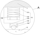
fig. 3 is an enlarged view of the structure at a in fig. 1.
Illustration of the drawings:
1. a box body; 2. a power box; 3. a motor; 4. a first gear; 5. a second gear; 6. a toothed belt; 7. a first rotating shaft; 8. a drum; 9. a hydraulic lever; 10. a feeding bin; 11. pushing the plate; 12. a scraper; 13. a buffer device; 14. a turntable; 15. a second rotating shaft; 16. a feed inlet; 17. a barrel cover; 18. a sewage draining outlet; 19. filtering with a screen; 20. a handle; 21. a solid material outlet; 131. a fixed block; 132. a spring; 133. a slide bar; 134. fixing the rod; 135. a ball bearing; 136. and a limiting block.
Detailed Description
The technical solutions in the embodiments of the present invention will be described clearly and completely with reference to the accompanying drawings in the embodiments of the present invention, and it is obvious that the described embodiments are only some embodiments of the present invention, not all embodiments. Based on the embodiments in the present invention, all other embodiments obtained by a person skilled in the art without creative work belong to the protection scope of the present invention.
In the description of the present invention, it should be noted that the terms "center", "upper", "lower", "left", "right", "vertical", "horizontal", "inner", "outer", and the like indicate orientations or positional relationships based on the orientations or positional relationships shown in the drawings, and are only for convenience of description and simplification of description, but do not indicate or imply that the device or element referred to must have a specific orientation, be constructed and operated in a specific orientation, and thus, should not be construed as limiting the present invention; the terms "first," "second," and "third" are used for descriptive purposes only and are not to be construed as indicating or implying relative importance, and furthermore, unless otherwise explicitly stated or limited, the terms "mounted," "connected," and "connected" are to be construed broadly and may be, for example, fixedly connected, detachably connected, or integrally connected; can be mechanically or electrically connected; they may be connected directly or indirectly through intervening media, or they may be interconnected between two elements. The specific meaning of the above terms in the present invention can be understood in specific cases to those skilled in the art.
Referring to fig. 1-3, the present invention provides an embodiment: a horizontal multi-section continuous sedimentation centrifuge comprises a box body 1, one side of the box body 1 is fixedly connected with a power box 2 to protect an internal mechanism, the bottom end of the inner side wall of the power box 2 is provided with a motor 3 to provide power, the end surface of a rotating shaft of the motor 3 is fixedly connected with a first gear 4, a second gear 5 is arranged in the power box 2 and positioned right above the first gear 4, a toothed belt 6 is sleeved on the surfaces of the first gear 4 and the second gear 5, a first rotating shaft 7 is fixedly connected to the position, close to the center of one side surface of the box body 1, of the second gear 5, one end of the first rotating shaft 7 penetrates through the side surface of the box body 1 and extends, the first gear 4 is driven to rotate by the motor 3, and the second gear 5 drives the;
the end face of the extending end of the first rotating shaft 7 is fixedly connected with a rotating drum 8, two hydraulic rods 9 are symmetrically arranged on the inner side wall of one side, close to the first rotating shaft 7, of the rotating drum 8 along the vertical direction, two feeding bins 10 are arranged on one side, far away from the rotating drum 8, of the hydraulic rods 9 for storing materials to be processed, the moving end of each hydraulic rod 9 penetrates through the side wall of the corresponding feeding bin 10 and extends, a push plate 11 is fixedly connected with the extending end of each hydraulic rod 9, scrapers 12 are symmetrically arranged at two ends of the side face of one side, far away from the corresponding hydraulic rod 9, of the push plate 11 and the scrapers 12 slide along the inner wall of the corresponding feeding bin 10, sediment inside the corresponding feeding bin 10 is cleared, and a plurality of buffer devices 13 are symmetrically arranged between the surfaces of two ends;
a turntable 14 is fixedly connected between opposite surfaces of one end of the feeding bin 10, which is far away from the hydraulic rod 9, a second rotating shaft 15 is fixedly connected to the center of the side surface of one side of the turntable 14, which is far away from the feeding bin 10, an end surface of one end of the second rotating shaft 15, which is far away from the turntable 14, is rotatably connected with the inner side wall of the box body 1, the first rotating shaft 7 drives the rotating drum 8 to rotate, meanwhile, the turntable 14 drives the second rotating shaft 15 to rotate, one side of the box body 1, which is close to the second rotating shaft 15, is provided with two feed inlets 16 for placing materials to be processed, the feed inlets 16 and the outlet of the feeding;
the central department of 1 bottom of box has seted up the liquid of drain 18 discharge separation, and drain 18 is close to 1 bottom of box and is provided with filter screen 19 and filters impurity, and filter screen 19 runs through drain 18, and 19 one side fixedly connected with handles 20 of filter screen, and the box 1 is close to 16 one side bottoms of feed inlet and has seted up the solid material of solid material export 21 discharge separation.
The buffer device 13 comprises a fixed block 131, a spring 132, a slide rod 133, a fixed rod 134, a ball 135 and a limited block 136, the fixed block 131 is fixedly connected to the inner wall of the box body 1, the spring 132 and the limited block 136 are arranged inside the fixed block 131, two slide rods 133 are symmetrically arranged at the bottom of the limited block 136 along the center, one end of each slide rod 133 penetrates through the bottom of the fixed block 131 and extends towards the rotary drum 8, the fixed rod 134 and the ball 135 are arranged between the opposite ends of the extending ends of the slide rods 133, the fixed rod 134 penetrates through the ball 135, the two ends of the fixed rod 134 are fixedly connected with the opposite surfaces of the two slide rods 133, the ball 135 rotates along with the rotary drum 8 when the rotary drum 8 rotates, the slide rods 133 slide up and down along with the vibration of the rotary drum 8 and compress the spring 132, thereby achieving a, the outer wall of the sliding rod 133 is connected with the inner wall of the first through hole in a sliding manner so as to be convenient to slide, a second through hole is formed at the penetrating position of the fixing rod 134 and the ball 135, the outer wall of the fixing rod 134 is connected with the inner wall of the second through hole in a rotating manner so as to be convenient to rotate, the surface of the ball 135 is smoothly attached to the outer wall of the rotary drum 8, the first gear 4, the second gear 5 and the toothed belt 6 are meshed and connected, a third through hole is formed at the penetrating position of the first rotary shaft 7 and the box body 1, the outer wall of the first rotary shaft 7 is connected with the inner wall of the third through hole in a rotating manner so as to be convenient to rotate, fourth through holes are formed at the penetrating positions of the moving ends of the two hydraulic rods 9 and the two feeding bins 10, the outer walls of the moving ends of the two hydraulic rods 9 are connected with the inner wall of the fourth through hole in a sliding manner so as, and the outer wall of the filter screen 19 is connected with the inner wall of the fifth through hole in a sliding manner, so that the filter screen 19 can be conveniently taken out for cleaning, and through holes are formed in the outer walls of the rotary drum 8 and the feeding bin 10, so that liquid can be conveniently discharged.
The working principle is as follows: the utility model discloses horizontal multistage sedimentation centrifuge in succession, open two bung 17 at first during the use, put the material that will process respectively in two feeding storehouses 10 and cover bung 17, then start motor 3, motor 3 drives first gear 4 and rotates, make second gear 5 drive first pivot 7 rotatory through the transmission of cingulum 6, first pivot 7 drives rotary drum 8 rotatory, carousel 14 drives second pivot 15 rotatory simultaneously and produces centrifugal force and carry out solid-liquid separation processing to the material, ball 135 also rotates along with it when rotary drum 8 rotates, slide bar 133 slides from top to bottom and compresses spring 132 along with the vibrations of rotary drum 8 simultaneously, thereby reduce vibrations when rotary drum 8 rotates, the liquid material that separates flows to box 1 inner wall through the through-hole on rotary drum 8 and feeding storehouse 10 surface, then discharge through drain 18, filter screen 19 can filter the impurity in the liquid material simultaneously, the solid material that separates then stays the inside feeding storehouse 10, after the rotary drum 8 stops rotating, the hydraulic rod 9 is started, the hydraulic rod 9 pushes the push plate 11 and the scraper 12 to slide along the inner wall of the feeding bin 10, solid materials are pushed out of the feeding bin 10 and then fall to the solid material outlet 21 and are discharged out of the device, and a collecting barrel can be placed below the sewage outlet 18 and the solid material outlet 21 to collect the discharged materials.
Finally, it should be noted that: although the present invention has been described in detail with reference to the foregoing embodiments, it will be apparent to those skilled in the art that modifications and variations can be made in the embodiments or in part of the technical features of the embodiments without departing from the spirit and the scope of the invention.
Claims (6)
1. A horizontal multi-section continuous sedimentation centrifuge comprises a box body (1), and is characterized in that one side of the box body (1) is fixedly connected with a power box (2), the bottom end of the inner side wall of the power box (2) is provided with a motor (3), the end face of a rotating shaft of the motor (3) is fixedly connected with a first gear (4), a second gear (5) is arranged in the power box (2) and is positioned right above the first gear (4), toothed belts (6) are sleeved on the surfaces of the first gear (4) and the second gear (5), a first rotating shaft (7) is fixedly connected to the center of one side face of the second gear (5) close to the box body (1), and one end of the first rotating shaft (7) penetrates through the side face of the box body (1) and extends;
the end face of the extending end of the first rotating shaft (7) is fixedly connected with a rotating drum (8), two hydraulic rods (9) are symmetrically arranged on the inner side wall of one side, close to the first rotating shaft (7), of the rotating drum (8) in the vertical direction, two feeding bins (10) are arranged on one side, away from the rotating drum (8), of the hydraulic rods (9), the moving end of each hydraulic rod (9) penetrates through the side wall of the corresponding feeding bin (10) and extends, a push plate (11) is fixedly connected with the extending end of each hydraulic rod (9), scrapers (12) are symmetrically arranged at two ends of the side face, away from the corresponding hydraulic rod (9), of the push plate (11), and a plurality of buffer devices (13) are symmetrically arranged between the surfaces of two ends of the rotating drum (8) and the inner wall of;
a turntable (14) is fixedly connected between opposite faces of one end, far away from the hydraulic rod (9), of the feeding bin (10), a second rotating shaft (15) is fixedly connected to the center of the side face of one side, far away from the feeding bin (10), of the turntable (14), the end face of one end, far away from the turntable (14), of the second rotating shaft (15) is rotatably connected with the inner side wall of the box body (1), two feeding ports (16) are formed in one side, close to the second rotating shaft (15), of the box body (1), outlets of the feeding ports (16) and the feeding bin (10) are in the same horizontal direction, and two barrel covers (17) are arranged on one side, far away from the power box (2), of;
the sewage draining outlet (18) is formed in the center of the bottom of the box body (1), a filter screen (19) is arranged at the position, close to the bottom of the box body (1), of the sewage draining outlet (18), the filter screen (19) penetrates through the sewage draining outlet (18), a handle (20) is fixedly connected to one side of the filter screen (19), and a solid material outlet (21) is formed in the bottom, close to one side of the feeding hole (16), of the box body (1).
2. The horizontal multistage continuous decanter centrifuge of claim 1, the buffer device (13) comprises a fixed block (131), a spring (132), a sliding rod (133), a fixed rod (134), a ball (135) and a limit block (136), the fixed block (131) is fixedly connected with the inner wall of the box body (1), a spring (132) and a limited block (136) are arranged inside the fixed block (131), the bottom of the limiting block (136) is symmetrically provided with two sliding rods (133) along the center, one end of the sliding rod (133) penetrates through the bottom of the fixed block (131) and extends towards the rotary drum (8), a fixing rod (134) and a ball (135) are arranged between the opposite surfaces of the extending ends of the sliding rod (133), the fixing rod (134) penetrates through the ball (135), and two ends of the fixed rod (134) are fixedly connected with the opposite surfaces of the two sliding rods (133).
3. The horizontal multistage continuous sedimentation centrifuge as claimed in claim 2, wherein the side surfaces of both sides of the limit block (136) are slidably connected with the inner side wall of the fixed block (131), a first through hole is formed at the penetrating position of the slide bar (133) and the fixed block (131), the outer wall of the slide bar (133) is slidably connected with the inner wall of the first through hole, a second through hole is formed at the penetrating position of the fixed bar (134) and the ball (135), the outer wall of the fixed bar (134) is rotatably connected with the inner wall of the second through hole, and the surface of the ball (135) is smoothly attached to the outer wall of the rotary drum (8).
4. The horizontal multi-section continuous sedimentation centrifuge as claimed in claim 1, wherein the first gear (4), the second gear (5) and the toothed belt (6) are meshed and connected, a third through hole is formed at the penetrating position of the first rotating shaft (7) and the box body (1), the outer wall of the first rotating shaft (7) is rotatably connected with the inner wall of the third through hole, a fourth through hole is formed at the penetrating position of the moving ends of the two hydraulic rods (9) and the two feeding bins (10), and the outer wall of the moving end of the two hydraulic rods (9) is slidably connected with the inner wall of the fourth through hole.
5. The horizontal multi-section continuous sedimentation centrifuge as claimed in claim 1, wherein the end faces of both ends of the push plate (11) and the scraper (12) are slidably connected with the inner side wall of the feeding bin (10), and the inner wall of the barrel cover (17) is slidably connected with the outer wall of the feeding port (16).
6. The horizontal multi-section continuous sedimentation centrifuge as claimed in claim 1, wherein a fifth through hole is formed at the penetration position of the filter screen (19) and the sewage draining outlet (18), the outer wall of the filter screen (19) is connected with the inner wall of the fifth through hole in a sliding manner, and a through hole is formed in the outer wall of the rotary drum (8) and the outer wall of the feeding bin (10).
Priority Applications (1)
| Application Number | Priority Date | Filing Date | Title |
|---|---|---|---|
| CN202021872459.8U CN213078820U (en) | 2020-09-01 | 2020-09-01 | Horizontal multi-section continuous sedimentation centrifuge |
Applications Claiming Priority (1)
| Application Number | Priority Date | Filing Date | Title |
|---|---|---|---|
| CN202021872459.8U CN213078820U (en) | 2020-09-01 | 2020-09-01 | Horizontal multi-section continuous sedimentation centrifuge |
Publications (1)
| Publication Number | Publication Date |
|---|---|
| CN213078820U true CN213078820U (en) | 2021-04-30 |
Family
ID=75633434
Family Applications (1)
| Application Number | Title | Priority Date | Filing Date |
|---|---|---|---|
| CN202021872459.8U Active CN213078820U (en) | 2020-09-01 | 2020-09-01 | Horizontal multi-section continuous sedimentation centrifuge |
Country Status (1)
| Country | Link |
|---|---|
| CN (1) | CN213078820U (en) |
Cited By (2)
| Publication number | Priority date | Publication date | Assignee | Title |
|---|---|---|---|---|
| CN116399090A (en) * | 2023-04-10 | 2023-07-07 | 日照市海洋生物工程技术研究中心 | A raw material dehydration device and method based on food processing |
| CN116921076A (en) * | 2023-07-26 | 2023-10-24 | 北新集团建材股份有限公司 | Centrifugal filtration classification device for gypsum mixed slurry |
-
2020
- 2020-09-01 CN CN202021872459.8U patent/CN213078820U/en active Active
Cited By (2)
| Publication number | Priority date | Publication date | Assignee | Title |
|---|---|---|---|---|
| CN116399090A (en) * | 2023-04-10 | 2023-07-07 | 日照市海洋生物工程技术研究中心 | A raw material dehydration device and method based on food processing |
| CN116921076A (en) * | 2023-07-26 | 2023-10-24 | 北新集团建材股份有限公司 | Centrifugal filtration classification device for gypsum mixed slurry |
Similar Documents
| Publication | Publication Date | Title |
|---|---|---|
| CN216404002U (en) | Multistage filter equipment for industrial water treatment | |
| CN116785791B (en) | A mud-water solid-liquid separation device with screening function | |
| CN215975002U (en) | A filling tank for sewage treatment | |
| CN211069150U (en) | Solid-liquid separation settling device | |
| CN114871843A (en) | Energy-saving digit control machine tool is with intelligent chip removal filtration system | |
| CN212789980U (en) | Bulldoze formula solid-liquid separation equipment | |
| CN218013401U (en) | Three-phase horizontal filtering centrifuge capable of efficiently separating | |
| CN220559509U (en) | Flat centrifuge convenient for discharging | |
| CN219111032U (en) | Essence liquid filter equipment | |
| CN218690537U (en) | Self-cleaning decontamination structure of centrifugal machine | |
| CN218794290U (en) | Silt treatment facility is used in water environment improvement | |
| CN217313938U (en) | Environment-friendly purifying device for oil filter | |
| CN216877962U (en) | High-efficient filter equipment of lubricating oil | |
| CN214569194U (en) | Accumulated coal cleaning device for electromechanical coal conveyor for coal mine | |
| CN213865886U (en) | Oily sludge-water three-phase horizontal centrifugal pry | |
| CN213000308U (en) | A centrifugal separator for apple processing | |
| CN213198901U (en) | A filter device for kitchen waste treatment equipment | |
| CN216155513U (en) | Scum treatment device for sewage treatment plant | |
| CN223774370U (en) | Fine separator | |
| CN214320534U (en) | Bidirectional piston pushing and filtering centrifuge | |
| CN218742533U (en) | Continuous separation device for sulfur in desulfurization waste liquid | |
| CN222694193U (en) | Solid-liquid separation equipment for environmental pollution treating agent | |
| CN222427387U (en) | Sewage treatment equipment for environmental protection engineering | |
| CN215653983U (en) | Centrifugal extraction device in copper-containing etching solution | |
| CN220345191U (en) | Fruit wine peel residue dry-wet separator |
Legal Events
| Date | Code | Title | Description |
|---|---|---|---|
| GR01 | Patent grant | ||
| GR01 | Patent grant |