Gasification pesticide applicator for preventing and controlling stored pests
Technical Field
The utility model relates to a gasification medicine applicator, in particular to a storage pest control gasification medicine applicator, which belongs to the technical field of medicine applicators.
Background
In the existing life, storage refers to a general term of storing and keeping materials and storing activities related to the storage through a warehouse, which is generated along with the generation of material storage and is developed along with the development of productivity, the storage is one of important links of commodity circulation and is also an important pillar of logistics activities, when storing articles which are easy to decay insects such as agricultural products, pest control is needed, and a method of spraying medicines is generally adopted in the prior art.
Through the retrieval, application number 201920211502.7's a storage pest control gasification medicine applicator, including the bottom plate of installing a plurality of universal wheels, the bottom plate upside is equipped with the movable block, be equipped with the cavity in the movable block, the movable block left and right sides slope symmetry is equipped with two outlet pipes, two the outlet pipe all with movable block fixed connection, and the one end fixedly connected with atomizer of movable block is kept away from to two outlet pipes, the movable block passes through elevating system and bottom plate fixed connection, movable block one side is equipped with the jar body, the internal rabbling mechanism that is equipped with of jar, the jar body is through connecting pipe and movable block fixed connection, fixedly connected with water pump on the connecting pipe. The utility model discloses it is rational in infrastructure, can adjust and spray the position, guarantee the homogeneity of medicine, and this patent can only be to the height that the medicine sprayed adjust to the rigidity of atomizer can't change the angle that the medicine sprayed, thereby lead to spraying of medicine not enough even easily, make the pest control effect reduce.
SUMMERY OF THE UTILITY MODEL
The to-be-solved technical problem of the utility model is to overcome the defects of the prior art and provide a gasification pesticide applicator for pest control in storage.
In order to solve the technical problem, the utility model provides a following technical scheme:
the utility model provides a gasification pesticide applicator for preventing and controlling pests in storage, which comprises a bottom plate, four corners of the bottom plate are all fixedly provided with self-locking wheels, one end of the top of the bottom plate is fixedly connected with a fixed frame, one end of the inside of the fixed frame is fixedly connected with a slide bar, the outer side of the slide bar is connected with a first slide block in a sliding way, one end of the bottom of the inner wall of the fixed frame, which is far away from the slide bar, is fixedly provided with a first servo motor, the output shaft of the first servo motor is fixedly connected with a screw rod through a coupler, the top of the screw rod is rotationally connected with the top of the inner wall of the fixed frame, the outer side of the screw rod is in threaded connection with a second sliding block, a transmission box is fixedly connected between the second sliding block and the first sliding block, the inside of transmission box is provided with drive mechanism, the top of transmission box is provided with sprays the mechanism, the top of bottom plate and the one side that is located fixed frame are provided with storage mechanism.
As a preferred scheme of the utility model, the transmission mechanism comprises a second servo motor, a second servo motor is fixedly arranged at one end of the bottom of the inner wall of the transmission box, an output shaft of the second servo motor is fixedly connected with a rotating disc, a limiting groove is arranged at the outer side of the rotating disc, a cross rod is fixedly connected with the inner wall of the transmission box and positioned above the rotating disc, a third slider is connected with the outer side of the cross rod and positioned at one side of the rotating disc in a sliding way, a fourth slider is connected with the outer side of the cross rod and positioned at one side of the third slider in a sliding way, connecting rods are fixedly connected with the bottoms of the third slider and the fourth slider, a transmission plate is fixedly connected between the bottoms of the two connecting rods, a rotating groove is arranged at one end of the transmission plate close to the rotating disc, a limiting roller is rotatably connected inside the rotating groove, the limiting roller extends to the inside of the limiting groove, the bottom of transmission box inner wall and the one side that is located second servo motor rotate and be connected with the axis of rotation, the outside of axis of rotation and the one side fixedly connected with drive gear that is located the driving plate, the top of axis of rotation extends to the top of transmission box.
As a preferred scheme of the utility model, the mechanism sprays is including connecting the hard tube, the top fixedly connected with of axis of rotation connects the hard tube, connect the one end fixedly connected with V font structure's of hard tube stand pipe, the equal fixedly connected with hollow structure's in both ends guide plate of guide plate, the inside of guide plate all communicates with each other with the inside of guide tube, the equal equidistance fixedly connected with atomizer in one side that the guide tube was kept away from to the guide plate, the inside of guide plate all communicates with each other with atomizer's inside, the one end fixedly connected with coupling hose that the guide tube was kept away from to the connection hard tube.
As a preferred scheme of the utility model, the storage mechanism includes the storage case, the top of bottom plate and the one side fixedly connected with storage case that is located fixed frame, the top of storage case is close to the one end fixedly connected with filling pipe of fixed frame, the filling pipe communicates with each other with the inside of storage case, the one end fixed mounting that the filling pipe was kept away from at the top of storage case has control panel, the top of bottom plate just is located fixed mounting between storage case and the fixed frame has the water pump, the input of water pump extends to the inside of storage case, coupling hose keeps away from the one end of connecting the hard tube and the output fixed connection of water pump.
As an optimized scheme of the utility model, the cover has return spring between the outside of horizontal pole and the inner wall that is located fourth slider and transmission box.
As an optimized scheme of the utility model, the top of bottom plate just is located two dead levers of one side fixedly connected with of storage case, two fixedly connected with push rod between the top of dead lever.
As a preferred scheme of the utility model, tooth has been seted up in the outside of driving plate, the tooth quantity in the driving plate outside is one to four with the tooth quantity in the drive gear outside than, just the tooth in the driving plate outside is connected with the tooth meshing in the drive gear outside.
As a preferred scheme of the utility model, equal and the control panel electric connection of first servo motor, second servo motor, water pump.
The utility model discloses the beneficial effect who reaches is: the utility model discloses compact structure, easy operation is convenient, and the practicality is strong, mutually supports through setting up screw drive and drive mechanism, not only can change the height that the medicine sprayed, but also can carry out the even swing of controlling to the medicine and spray to make equipment to spraying more even of medicine, the scope of spraying is wider, has avoided spraying of medicine position too single, and then very big improvement the effect of pest control.
Drawings
The accompanying drawings are included to provide a further understanding of the invention, and are incorporated in and constitute a part of this specification, illustrate embodiments of the invention, and together with the description serve to explain the invention and not to limit the invention. In the drawings:
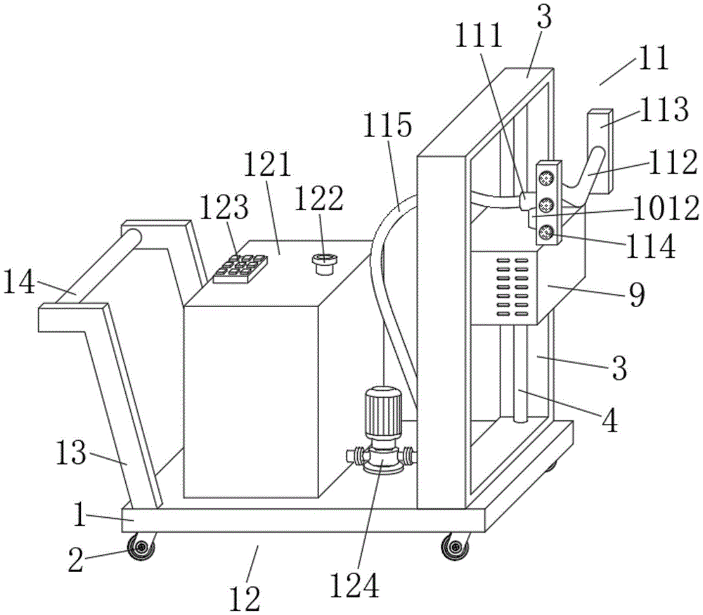
FIG. 1 is a schematic view of the overall structure of the present invention;
FIG. 2 is a front view of the present invention;
fig. 3 is a schematic view of the internal structure of the fixing frame of the present invention;
fig. 4 is a schematic view of the internal structure of the transmission case of the present invention.
In the figure: 1. a base plate; 2. a self-locking wheel; 3. a fixing frame; 4. a slide bar; 5. a first slider; 6. a first servo motor; 7. a screw rod; 8. a second slider; 9. a transmission box; 10. a transmission mechanism; 101. a second servo motor; 102. rotating the disc; 103. a limiting groove; 104. a cross bar; 105. a third slider; 106. a fourth slider; 107. a return spring; 108. a connecting rod; 109. a drive plate; 1010. a rotating groove; 1011. limiting the idler wheel; 1012. a rotating shaft; 1013. a transmission gear; 11. a spraying mechanism; 111. connecting a hard pipe; 112. a guide tube; 113. a baffle; 114. an atomizing spray head; 115. a connecting hose; 12. a storage mechanism; 121. a material storage box; 122. a filling pipe; 123. a control panel; 124. a water pump; 13. fixing the rod; 14. a push rod.
Detailed Description
The preferred embodiments of the present invention will be described in conjunction with the accompanying drawings, and it will be understood that they are presented herein only to illustrate and explain the present invention, and not to limit the present invention.
Examples
As shown in fig. 1-4, the utility model provides a gasified pesticide applicator for pest control in storage, which comprises a bottom plate 1, four corners of the bottom plate 1 are all fixedly provided with self-locking wheels 2, and the self-locking wheels 2 are convenient for better moving and fixing the device; one end of the top of the bottom plate 1 is fixedly connected with a fixed frame 3, one end inside the fixed frame 3 is fixedly connected with a slide bar 4, the outer side of the slide bar 4 is connected with a first slide block 5 in a sliding way, one end of the bottom of the inner wall of the fixed frame 3, which is far away from the slide bar 4, is fixedly provided with a first servo motor 6, the output shaft of the first servo motor 6 is fixedly connected with a lead screw 7 through a shaft coupling, the top of the lead screw 7 is rotatably connected with the top of the inner wall of the fixed frame 3, the outer side of the lead screw 7 is connected with a second slide block 8 in a, the first servo motor 6 drives the screw rod 7 to rotate, thereby driving the second slide block 8 to move up and down on the outer side of the screw rod 7, further, the transmission box 9 can move up and down in the fixed frame 3 under the limit between the first sliding block 5 and the sliding rod 4, so that the height of the sprayed medicine can be better adjusted; the transmission mechanism 10 is arranged in the transmission box 9, the spraying mechanism 11 is arranged at the top of the transmission box 9, and the storage mechanism 12 is arranged at the top of the bottom plate 1 and on one side of the fixed frame 3.
Further, the transmission mechanism 10 comprises a second servo motor 101, one end of the bottom of the inner wall of the transmission box 9 is fixedly provided with the second servo motor 101, an output shaft of the second servo motor 101 is fixedly connected with a rotating disc 102, and the rotating disc 102 is eccentrically connected with the output shaft of the second servo motor 101, so that better transmission is facilitated; a limiting groove 103 is formed on the outer side of the rotating disc 102, a cross rod 104 is fixedly connected to the inner wall of the transmission box 9 and positioned above the rotating disc 102, a third slider 105 is slidably connected to the outer side of the cross rod 104 and positioned on one side of the rotating disc 102, a fourth slider 106 is slidably connected to the outer side of the cross rod 104 and positioned on one side of the third slider 105, connecting rods 108 are fixedly connected to the bottoms of the third slider 105 and the fourth slider 106, a transmission plate 109 is fixedly connected between the bottoms of the two connecting rods 108, a rotating groove 1010 is formed in one end, close to the rotating disc 102, of the transmission plate 109, a limiting roller 1011 is rotatably connected to the inside of the rotating groove 1010, the limiting roller 1011 extends to the inside of the limiting groove 103 and is rotatably connected with the limiting groove 103, a rotating shaft is rotatably connected to the bottom 1012 of the inner wall of the transmission box 9 and positioned on one side of the second servo motor 101, the top of axis of rotation 1012 extends to the top of transmission box 9, drives the rolling disc 102 through second servo motor 101 and rotates to through the cooperation between spacing groove 103 and the spacing gyro wheel 1011, be convenient for better promotion driving plate 109, connecting rod 108, third slider 105 and fourth slider 106 slide in the outside of horizontal pole 104, thereby better pass through driving plate 109 and drive gear 1013 carry out the transmission.
Further, the spraying mechanism 11 includes a connection hard pipe 111, the top fixedly connected with of axis of rotation 1012 connects hard pipe 111, the one end fixedly connected with V font structure's of connection hard pipe 111 stand pipe 112, the equal fixedly connected with hollow structure's in both ends guide pipe 112 guide plate 113, the inside of guide plate 113 all communicates with each other with the inside of guide pipe 112, the equal equidistance fixedly connected with atomizer 114 in one side that guide plate 113 kept away from guide pipe 112, the inside of guide plate 113 all communicates with each other with atomizer 114's inside, the one end fixedly connected with coupling hose 115 that guide pipe 112 was kept away from to connection hard pipe 111, the liquid medicine that carries through coupling hose 115 passes the inside that connects hard pipe 111 entering guide pipe 112, then get into the inside of guide plate 113, spout through atomizer 114 at last, thereby better spraying operation.
Further, the storage mechanism 12 includes a storage tank 121, the storage tank 121 is fixedly connected to the top of the base plate 1 and located on one side of the fixing frame 3, a filler pipe 122 is fixedly connected to one end of the top of the storage tank 121 close to the fixing frame 3, the filler pipe 122 is communicated with the inside of the storage tank 121, a control panel 123 is fixedly installed at one end of the top of the storage tank 121 far from the filler pipe 122, a water pump 124 is fixedly installed at the top of the base plate 1 and located between the storage tank 121 and the fixing frame 3, an input end of the water pump 124 extends to the inside of the storage tank 121, one end of the connecting hose 115 far from the connecting hard pipe 111 is fixedly connected to an output end of, the filling tube 122 facilitates better filling of the mixed liquid medicine into the interior of the storage tank 121, the liquid medicine stored in the storage tank 121 is then preferably delivered into the connection hose 115 by the water pump 124.
Furthermore, a return spring 107 is sleeved outside the cross bar 104 and between the fourth slider 106 and the inner wall of the transmission box 9, and the limiting roller 1011 is always located inside the limiting groove 103 under the elastic force action of the return spring 107.
Further, the top of bottom plate 1 and the two dead levers 13 of one side fixedly connected with that are located storage case 121, fixedly connected with push rod 14 between the top of two dead levers 13, through the cooperation between dead lever 13 and the push rod 14, be convenient for better promote equipment.
Furthermore, the outer side of the transmission plate 109 is provided with teeth, the ratio of the number of the teeth on the outer side of the transmission plate 109 to the number of the teeth on the outer side of the transmission gear 1013 is one to four, and the teeth on the outer side of the transmission plate 109 are meshed and connected with the teeth on the outer side of the transmission gear 1013, so that the transmission gear 1013 and the rotating shaft 1012 can be driven to rotate in a reciprocating manner better through the matching between the teeth on the outer side of the transmission plate 109 and the teeth on the outer side of the transmission gear 1013.
Furthermore, first servo motor 6, second servo motor 101, water pump 124 all with control panel 123 electric connection, be convenient for better control the equipment is whole through control panel 123.
Specifically, when the spraying device is used, firstly, the mixed liquid medicine can be filled into the storage box 121 through the filling pipe 122, then the device is powered on, the device is pushed through the matching between the fixing rod 13 and the push rod 14, when different height positions need to be sprayed, the first servo motor 6 can be controlled to work through the control panel 123 to drive the lead screw 7 to rotate, so that the second slider 8 is driven to move up and down outside the lead screw 7, further, the transmission box 9 can move up and down inside the fixing frame 3 under the limiting between the first slider 5 and the slide rod 4, so that the spraying height can be better adjusted, then, the second servo motor 101 can be controlled to work through the control panel 123 to drive the rotating disc 102 to rotate, so that the transmission plate 109 and the limiting roller 1011 can be better pushed through the matching between the limiting groove 103 and the limiting roller 1011, so that the transmission plate 109 and the driving plate 109 can be better, The connecting rod 108, the third slider 105 and the fourth slider 106 slide outside the cross rod 104, and simultaneously, through the elastic force of the return spring 107, the limiting roller 1011 is always located inside the limiting groove 103, thereby facilitating better driving of the transmission plate 109 to move left and right, facilitating better driving of the transmission gear 1013 and the rotation shaft 1012 to rotate back and forth through the cooperation between the teeth outside the transmission plate 109 and the teeth outside the transmission gear 1013, thereby better driving of the spraying mechanism 11 to swing back and forth left and right, further increasing the spraying effect, in addition, the liquid medicine stored inside the storage box 121 is conveyed through the water pump 124, so that the liquid medicine enters the inside of the connecting hose 115, the liquid medicine conveyed through the connecting hose 115 passes through the connecting hard pipe 111 to enter the inside of the guide pipe 112, then enters the inside of the guide plate 113, and finally is sprayed out through the atomizing nozzle 114, thereby performing a spraying operation better.
Finally, it should be noted that: although the present invention has been described in detail with reference to the foregoing embodiments, it will be apparent to those skilled in the art that modifications may be made to the embodiments described in the foregoing embodiments, or equivalents may be substituted for elements thereof. Any modification, equivalent replacement, or improvement made within the spirit and principle of the present invention should be included in the protection scope of the present invention.