CN213053215U - Workpiece limiting device of spot welding machine - Google Patents
Workpiece limiting device of spot welding machine Download PDFInfo
- Publication number
- CN213053215U CN213053215U CN202021475273.9U CN202021475273U CN213053215U CN 213053215 U CN213053215 U CN 213053215U CN 202021475273 U CN202021475273 U CN 202021475273U CN 213053215 U CN213053215 U CN 213053215U
- Authority
- CN
- China
- Prior art keywords
- limiting plate
- workpiece
- limiting
- work piece
- welding machine
- Prior art date
- Legal status (The legal status is an assumption and is not a legal conclusion. Google has not performed a legal analysis and makes no representation as to the accuracy of the status listed.)
- Active
Links
Images


Abstract
The application relates to the technical field of machining limiting devices, and particularly relates to a workpiece limiting device of a spot welding machine. When the workpiece is placed on the welding table to be welded, one side of the workpiece is abutted to the limiting plate, and the workpiece is limited in the horizontal direction. This application has the stability that improves the work piece and place on the welding bench, and then improves work piece welding quality's effect.
Description
Technical Field
The application relates to the field of machining limiting devices, in particular to a workpiece limiting device of a spot welding machine.
Background
The spot welder is a mechanical device which adopts the principle of double-sided double-point overcurrent welding, when in work, two electrodes pressurize a workpiece to enable two layers of metal to form a certain contact resistance under the pressure of the two electrodes, and when welding current flows from one electrode to the other electrode, instant thermal welding is formed at the two contact resistance points.
The existing Chinese patent with reference to publication number CN111185655A discloses a spot welding machine, which comprises a welding machine main body, wherein a welding seat is fixedly connected to the top of the welding machine main body, a driving motor is fixedly connected to the top on the right side of the welding seat, a driving rotating shaft is fixedly connected to an output shaft of the driving motor, a first gear is fixedly connected to the bottom of the driving rotating shaft, and a fixing groove is formed in the right side of the welding seat and located below the first gear. Through driving motor, the drive pivot, first gear, first bearing, fixed pivot, rotatory pivot, the second bearing, the second gear, the thread groove, the thread pivot, the cylinder, the soldered connection, the welding bench, spout and slider are mutually supported, the problem of the point welding machine of common mechatronic is not convenient for operate has been solved, can carry out horizontal position's adjustment to the soldered connection automatically, can weld a plurality of solder joints, not only reduce workman's intensity of labour, and time and labor saving, make welding efficiency improve, bring very big inconvenience for weldment work.
In view of the above related technologies, the inventor believes that a workpiece is placed on a welding table, and when the workpiece is welded, the workpiece lacks a limiting device to limit and fix the workpiece, thereby affecting the welding quality of the workpiece.
SUMMERY OF THE UTILITY MODEL
In order to carry out spacing and then improve work piece welding quality to the work piece, this application provides a spot welder's work piece stop device.
The application provides a work piece stop device of spot welder adopts following technical scheme:
the utility model provides a work piece stop device of spot welder, includes the welding bench, can dismantle on the welding bench and be connected with the limiting plate, and the setting of limiting plate perpendicular to welding bench, bolt and bolt bottom and welding bench threaded connection are worn to be equipped with at the limiting plate top.
By adopting the technical scheme, when the workpiece is placed on the welding table to be welded, the electrode arm of the spot welding machine is in contact with the workpiece and forms instant hot welding to weld the workpiece, one side of the workpiece is abutted against the limiting plate, the workpiece is limited in the horizontal direction, the stability of the workpiece placed on the welding table is improved, and the welding quality of the workpiece is further improved.
Preferably, limiting block is fixedly connected with one end of the limiting plate, and the limiting block is clamped on the limiting plate and is perpendicular to the limiting plate.
Through adopting above-mentioned technical scheme, the work piece is placed on the welding bench with the limiting plate butt after, the work piece is close to stopper one side and stopper butt, and the stopper sets up with the limiting plate is perpendicular, carries on spacingly to the work piece from being on a parallel with two directions of limiting plate and perpendicular to limiting plate, and the work piece is placed the position and is more accurate, stable, has restricted the removal of work piece, has improved the steadiness of work piece and then has improved work piece welding quality.
Preferably, the limiting plate is kept away from stopper one end and can be dismantled and be connected with the cylinder, and the cylinder is just to setting up with the stopper.
Through adopting above-mentioned technical scheme, the work piece is placed on the welding bench, and behind the lateral wall of work piece and limiting plate and stopper butt, the telescopic link of cylinder stretches out and is close to cylinder one side butt with the work piece, and the cylinder is just to setting up with the stopper, and the work piece is placed between stopper and cylinder and is pressed from both sides tightly fixed, has improved the stability that the work piece was placed, and the work piece presss from both sides the fastening and has liberated both hands, needn't right the work piece with the hand, has improved the convenience of operation.
Preferably, the limiting plate slides up and is connected with the fixed block, and the fixed block is fixed with the limiting plate through the bolt, and the cylinder sets firmly on the fixed block, and the piston rod of cylinder passes the fixed block setting.
Through adopting above-mentioned technical scheme, the fixed block slides with the limiting plate and is connected, and the fixed block can be along the limiting plate towards the direction horizontal slip that is close to or deviates from the stopper, and the bolt of screwing after the position is confirmed fixes, adjusts the distance between fixed block and the stopper for adapt to the work piece of different width, improve convenience and the practicality of using.
Preferably, one end of the telescopic rod of the air cylinder, which is close to the limiting block, is fixedly connected with a contact plate.
Through adopting above-mentioned technical scheme, the telescopic link of cylinder stretches out back contact plate and work piece butt, has increased the area of contact with the work piece, has improved the stability of contact.
Preferably, the welding bench top surface can be dismantled and be connected with the rolling subassembly, and the rolling subassembly includes support frame and rolling member, and the support frame can be dismantled and connect in the welding bench top surface, and the uncovered setting in support frame top is seted up flutedly, and both ends card is located in the recess and is rotated with the support frame and be connected about the rolling member.
Through adopting above-mentioned technical scheme, place the work piece on the rolling subassembly, promote the work piece towards the direction that is close to the limiting plate, the rolling member rotates around the axle center, and the work piece removes towards the direction that is close to the limiting plate, and the rolling member rotates the resistance that receives when having reduced the work piece and removing, makes the work piece remove more convenient laborsaving, has improved the convenience of placing the work piece.
Preferably, support frame bottom fixedly connected with slider, the welding bench top surface just has seted up the spout to slider department, spout and limiting plate parallel arrangement, the slider insert locate in the spout and with spout sliding connection, the support frame is close to welding bench edge one side fixedly connected with setting element, the setting element can be dismantled with the welding bench edge and be connected.
Through adopting above-mentioned technical scheme, when adjusting rolling assembly's position, the slider is inserted and is located in the spout and with spout horizontal sliding connection, the slider along spout horizontal sliding, also along with horizontal sliding with the fixed continuous support frame of slider, the setting element is fixed the support frame afterwards, the work piece is placed on rolling assembly, prevents that the work piece from taking place the skew and toppling over, maintains the equilibrium of work piece to adapt to the work piece of not unidimensional, improve the stability of work piece.
Preferably, the rolling assembly is provided in plurality, and the plurality of rolling assemblies are arranged in parallel with each other.
By adopting the technical scheme, the workpieces are placed on the rolling assemblies, and the rolling assemblies are arranged in parallel, so that the workpieces can be better supported, the balance of the workpieces is maintained, and the stability of the workpieces is improved.
In summary, the present application includes at least one of the following beneficial technical effects:
1. by arranging the limiting plate, the effect of limiting the workpiece and improving the stability of the workpiece is achieved;
2. by arranging the air cylinder, the effect of improving the stability of the workpiece is generated;
3. through setting up the rolling assembly, produced the effect that improves the work piece and place the convenience.
Drawings
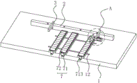
FIG. 1 is a schematic view of the overall structure of a workpiece limiting device of a spot welding machine according to an embodiment of the present application;
FIG. 2 is an enlarged view at A in FIG. 1;
figure 3 is a partial view highlighting the slider-runner configuration.
Description of reference numerals: 1. a welding table; 12. a chute; 2. a limiting plate; 3. a limiting block; 4. a cylinder; 5. a fixed block; 6. a contact plate; 7. a rolling component; 71. a support frame; 711. a groove; 712. a slider; 713. a positioning member; 72. a rolling member.
Detailed Description
The present application is described in further detail below with reference to figures 1-3.
The embodiment of the application discloses a workpiece limiting device of a spot welding machine. Referring to fig. 1, the workpiece limiting device of the spot welding machine comprises a welding table 1, a limiting plate 2 is detachably connected to the welding table 1, the limiting plate 2 is perpendicular to the welding table 1, and a bolt is arranged at the top of the limiting plate 2 in a penetrating mode, and the bottom of the bolt is in threaded connection with the welding table 1. The work piece is placed on welding bench 1, and when welding, one side of work piece and limiting plate 2 butt are spacing to the work piece from the horizontal direction, improve the stability of work piece placing on welding bench 1, and then improve the welding quality of work piece.
Referring to fig. 1, 2 one ends of limiting plate can be dismantled and be connected with stopper 3, and stopper 3 card is located on limiting plate 2 and is set up perpendicularly with limiting plate 2. The work piece is placed on welding bench 1 and behind 2 butts of limiting plate, and the work piece is close to 3 one sides of stopper and 3 butts of stopper, and stopper 3 sets up with limiting plate 2 is perpendicular, carries on spacingly to the work piece from being on a parallel with two directions of limiting plate 2 and perpendicular to limiting plate 2, and the work piece is placed the position and is more accurate, stable, has restricted the removal of work piece, has improved the steadiness of work piece and then has improved work piece welding quality.
Combine fig. 1 and fig. 2, limiting plate 2 keeps away from 3 one ends of stopper and can dismantle and be connected with cylinder 4, and cylinder 4 is just to setting up with stopper 3, and the telescopic link of cylinder 4 is close to 3 one end fixedly connected with contact plates 6 of stopper. The work piece is placed on welding bench 1, and behind the lateral wall and the limiting plate 2 and the 3 butt of stopper of work piece, the telescopic link of cylinder 4 stretches out, and the contact plate 6 that links to each other with the telescopic link of cylinder 4 is close to one side butt of cylinder 4 with the work piece, and cylinder 4 is just to setting up with stopper 3, and the work piece is placed between stopper 3 and cylinder 4 and is pressed from both sides tightly fixedly, carries on spacingly to the work piece from being on a parallel with the 2 directions of limiting plate, has improved the stability that the work piece was. Limiting plate 2 slides on the top and is connected with fixed block 5, and fixed block 5 is fixed with limiting plate 2 through the bolt, and cylinder 4 sets firmly on fixed block 5, and the piston rod of cylinder 4 passes fixed block 5 and sets up. Fixed block 5 can be along limiting plate 2 towards being close to or deviating from stopper 3's direction horizontal slip, and the bolt of screwing after the position is confirmed fixes, adjusts the distance between fixed block 5 and the stopper 3 for adapt to the work piece of different width, improve convenience and the practicality of using.
With reference to fig. 1 and 3, the top surface of the welding table 1 is detachably connected with a plurality of rolling assemblies 7 parallel to each other, each rolling assembly 7 comprises a support frame 71 and a rolling element 72, the support frame 71 is detachably connected to the top surface of the welding table 1, a groove 711 is formed in an opening of the top of the support frame 71, and the left end and the right end of each rolling element 72 are clamped in the groove 711 and are rotatably connected with the support frame 71. The workpiece is placed on the rolling assembly 7, the workpiece is pushed towards the direction close to the limiting plate 2, the rolling piece 72 rotates around the axis, the workpiece moves towards the direction close to the limiting plate 2, and the resistance force applied when the workpiece moves is reduced by the rotation of the rolling piece 72, so that the workpiece moves more conveniently and more labor-saving, and the convenience of placing the workpiece is improved; the workpieces are placed on the plurality of parallel rolling assemblies 7, so that the workpieces can be better supported, the balance of the workpieces is maintained, and the stability of the workpieces is improved.
With reference to fig. 1 and fig. 3, a sliding block 712 is fixedly connected to the bottom of the supporting frame 71, a sliding groove 12 is formed in a position, opposite to the sliding block 712, of the top surface of the welding table 1, the sliding groove 12 is parallel to the limiting plate 2, the sliding block 712 is inserted into the sliding groove 12 and is slidably connected with the sliding groove 12, a positioning member 713 is fixedly connected to one side of the supporting frame 71, which is close to the edge of the welding table 1, and the positioning member 713 is detachably connected. When the position of the rolling component 7 is adjusted, the sliding block 712 is inserted into the sliding groove 12 and is in horizontal sliding connection with the sliding groove 12, the sliding block 712 horizontally slides along the sliding groove 12, the supporting frame 71 fixedly connected with the sliding block 712 also horizontally slides, then the positioning component 713 fixes the supporting frame 71, the workpiece is placed on the rolling component 7, the workpiece is prevented from being deviated and toppled, the balance of the workpiece is maintained, so that the workpiece is suitable for workpieces with different sizes, and the stability and the use convenience of the workpiece are improved.
The implementation principle of the workpiece limiting device of the spot welding machine is as follows: when the workpiece limiting device of the spot welding machine is used, firstly, the rolling component 7 is adjusted according to the size of the workpiece, and the relative position of the rolling component 7 on the welding table 1 ensures that the rolling component 7 has a better supporting effect on the workpiece; after rolling subassembly 7 is adjusted, place the work piece on rolling subassembly 7, to the direction that is close to limiting plate 2 promote and with limiting plate 2 and 3 butts of stopper, to the position of the direction adjustment fixed block 5 that is close to the work piece, make with the fixed contact plate 6 and the work piece butt that link to each other of 4 telescopic links of cylinder, play spacing effect to the work piece, improve the stability that the work piece was placed, and then improve welding quality.
The above embodiments are preferred embodiments of the present application, and the protection scope of the present application is not limited by the above embodiments, so: all equivalent changes made according to the structure, shape and principle of the present application shall be covered by the protection scope of the present application.
Claims (8)
1. The utility model provides a work piece stop device of spot welder, includes welding bench (1), its characterized in that: can dismantle on welding bench (1) and be connected with limiting plate (2), and limiting plate (2) perpendicular to welding bench (1) sets up, and bolt bottom and welding bench threaded connection are worn to be equipped with at limiting plate (2) top.
2. The workpiece limiting device of the spot welding machine as recited in claim 1, wherein: limiting block (3) is fixedly connected with one end of the limiting plate (2), and the limiting block (3) is clamped on the limiting plate (2) and is perpendicular to the limiting plate (2).
3. The workpiece limiting device of the spot welding machine as claimed in claim 2, wherein: limiting plate (2) keep away from stopper (3) one end and can dismantle and be connected with cylinder (4), cylinder (4) just to setting up with stopper (3).
4. The workpiece limiting device of the spot welding machine as claimed in claim 3, wherein: limiting plate (2) slide upward and are connected with fixed block (5), and fixed block (5) are fixed through bolt and limiting plate (2), and cylinder (4) set firmly on fixed block (5), and the piston rod of cylinder (4) passes fixed block (5) and sets up.
5. The workpiece limiting device of the spot welding machine as claimed in claim 3, wherein: and one end of the telescopic rod of the air cylinder (4) close to the limiting block (3) is fixedly connected with a contact plate (6).
6. The workpiece limiting device of the spot welding machine as recited in claim 1, wherein: welding bench (1) top surface can be dismantled and be connected with rolling subassembly (7), and rolling subassembly (7) include support frame (71) and rolling member (72), and support frame (71) can be dismantled and connect in welding bench (1) top surface, and the uncovered setting in support frame (71) top is seted up fluted (711), and both ends card is located in recess (711) and is rotated with support frame (71) and be connected about rolling member (72).
7. The workpiece limiting device of the spot welding machine as recited in claim 6, wherein: support frame (71) bottom fixedly connected with slider (712), spout (12) have just been seted up to slider (712) to welding bench (1) top surface, spout (12) and limiting plate (2) parallel arrangement, slider (712) insert locate in spout (12) and with spout (12) sliding connection, support frame (71) are close to welding bench (1) edge one side fixedly connected with setting element (713), and setting element (713) can be dismantled with welding bench (1) edge and be connected.
8. The workpiece limiting device of the spot welding machine as recited in claim 6, wherein: the rolling assemblies (7) are arranged in a plurality, and the rolling assemblies (7) are arranged in parallel.
Priority Applications (1)
| Application Number | Priority Date | Filing Date | Title |
|---|---|---|---|
| CN202021475273.9U CN213053215U (en) | 2020-07-23 | 2020-07-23 | Workpiece limiting device of spot welding machine |
Applications Claiming Priority (1)
| Application Number | Priority Date | Filing Date | Title |
|---|---|---|---|
| CN202021475273.9U CN213053215U (en) | 2020-07-23 | 2020-07-23 | Workpiece limiting device of spot welding machine |
Publications (1)
| Publication Number | Publication Date |
|---|---|
| CN213053215U true CN213053215U (en) | 2021-04-27 |
Family
ID=75575635
Family Applications (1)
| Application Number | Title | Priority Date | Filing Date |
|---|---|---|---|
| CN202021475273.9U Active CN213053215U (en) | 2020-07-23 | 2020-07-23 | Workpiece limiting device of spot welding machine |
Country Status (1)
| Country | Link |
|---|---|
| CN (1) | CN213053215U (en) |
-
2020
- 2020-07-23 CN CN202021475273.9U patent/CN213053215U/en active Active
Similar Documents
| Publication | Publication Date | Title |
|---|---|---|
| CN213053215U (en) | Workpiece limiting device of spot welding machine | |
| CN210306213U (en) | High-efficient portable fixing base connection structure for spot welding machine | |
| CN210588863U (en) | Multi-angle labor-saving flat tongs | |
| CN214558716U (en) | Adjustable fixture for welding machine | |
| CN216802260U (en) | Extensive applicability's welder uses welding jig | |
| CN214769369U (en) | Auxiliary tool for cutting oblique angle of sawing machine | |
| CN111644793B (en) | Automobile punching part welding jig positioner | |
| CN201543952U (en) | Gas shielded welding clamping apparatus | |
| CN210677324U (en) | Weldment fixing device for joint butt-welding machine of front fork head pipe | |
| CN211072718U (en) | Efficient machine tool fixture | |
| CN211102343U (en) | Multi-station semi-automatic high-precision welding machine | |
| CN210756015U (en) | Simple cushion block device for spot welding of special-shaped workpiece | |
| CN217316538U (en) | Electric welding support for mechanical welding | |
| CN210209012U (en) | Seam welder | |
| CN219026505U (en) | Clamp for vertical welding of stainless steel | |
| CN220547818U (en) | Welding angle adjusting and clamping device | |
| CN218311414U (en) | Spot welding auxiliary device with positioning mechanism | |
| CN218533293U (en) | Repair welding device for valve casting | |
| CN215238880U (en) | Stand welding position frock | |
| CN216264366U (en) | Welding workpiece fixture | |
| CN213257845U (en) | Stable welding jig | |
| CN214161860U (en) | Anti-deformation welding jig frame for steel structure machining | |
| CN220464128U (en) | Processing positioning mechanism convenient to adjustment work piece position | |
| CN213614739U (en) | Spot welding positioning tool for circular base | |
| CN217316611U (en) | Clamping tool capable of adjusting weld gap for brazing of air conditioner heat exchanger |
Legal Events
| Date | Code | Title | Description |
|---|---|---|---|
| GR01 | Patent grant | ||
| GR01 | Patent grant |