CN213052805U - Drilling machine - Google Patents
Drilling machine Download PDFInfo
- Publication number
- CN213052805U CN213052805U CN202022144084.XU CN202022144084U CN213052805U CN 213052805 U CN213052805 U CN 213052805U CN 202022144084 U CN202022144084 U CN 202022144084U CN 213052805 U CN213052805 U CN 213052805U
- Authority
- CN
- China
- Prior art keywords
- drilling machine
- workpiece
- clamping
- pair
- plate body
- Prior art date
- Legal status (The legal status is an assumption and is not a legal conclusion. Google has not performed a legal analysis and makes no representation as to the accuracy of the status listed.)
- Expired - Fee Related
Links
- 238000005553 drilling Methods 0.000 title claims abstract description 34
- 230000007246 mechanism Effects 0.000 claims abstract description 16
- 238000009434 installation Methods 0.000 claims description 8
- 238000003754 machining Methods 0.000 abstract description 13
- 230000000694 effects Effects 0.000 abstract description 3
- 230000033001 locomotion Effects 0.000 description 6
- 238000000034 method Methods 0.000 description 3
- 230000006835 compression Effects 0.000 description 2
- 238000007906 compression Methods 0.000 description 2
- 230000001360 synchronised effect Effects 0.000 description 2
- 230000009286 beneficial effect Effects 0.000 description 1
- 230000000149 penetrating effect Effects 0.000 description 1
- 238000010079 rubber tapping Methods 0.000 description 1
Images


Landscapes
- Drilling And Boring (AREA)
Abstract
The utility model relates to a drilling machine field discloses a drilling machine, which comprises a frame, set up the workstation in the drilling machine frame, set up stand on the drilling machine workstation and set up the headstock on the drilling machine stand, be provided with a pair of supporting rod on the drilling machine workstation side by side, the terminal surface all is provided with the sliding block under the both ends of drilling machine supporting rod, it has the sliding hole that supplies the drilling machine sliding block to slide to run through on the drilling machine workstation, and the below of drilling machine workstation is provided with and is used for controlling the actuating mechanism that a pair of drilling machine sliding block is close to each other or keeps away from. The utility model has the advantages of it is following and effect: the clamping rods which are close to or far away from each other are arranged to rapidly clamp and fix the workpiece, the pair of clamping rods is utilized to realize automatic centering and correction of the workpiece, and the clamping efficiency and the machining efficiency of the workpiece are increased.
Description
Technical Field
The utility model relates to a drilling machine field, in particular to drilling machine.
Background
A drill press refers to a machine tool that uses a drill bit to form a hole in a workpiece, and usually the drill bit rotates as a primary motion and the drill bit moves axially as a feed motion. The drilling machine is simple in structure, can drill through holes and blind holes, and can perform reaming, spot facing, reaming, tapping and other processing.
Chinese patent CN210435401U discloses a novel drilling machine, which comprises a drilling machine base, a right side fixedly connected with workpiece fixing table at the top of the drilling machine base, a right side fixedly connected with round stand column at the top of the workpiece fixing table, a headstock which is slidably connected with the round stand column in a sleeved manner, and a drilling spindle box fixedly connected to the left side of the headstock.
When the drilling machine is used, a workpiece is placed and fixed on the workpiece fixing table, and then drilling is carried out on the workpiece. When a traditional workpiece is fixed, the workpiece is clamped and fixed by a chuck, the fixing process is complex, the machining efficiency of the workpiece is influenced, and the improvement is needed.
SUMMERY OF THE UTILITY MODEL
Not enough to prior art exists, the utility model aims at providing a drilling machine has the effect that improves work efficiency.
The above technical purpose of the present invention can be achieved by the following technical solutions: the utility model provides a drilling machine, include the frame, set up in workstation in the frame, vertical set up in stand on the workstation with set up in headstock on the stand, be provided with a pair of supporting rod on the workstation side by side, the terminal surface all is provided with the sliding block under the both ends of supporting rod, it has the confession to run through on the workstation the sliding hole that the sliding block slided, and the below of workstation is provided with and is used for controlling a pair ofly the sliding block is close to each other or the actuating mechanism who keeps away from.
Through adopting above-mentioned technical scheme, when using above-mentioned drilling machine, place the work piece on the workstation, then utilize actuating mechanism control a pair of sliding block to be close to each other, the sliding block drives the clamping rod synchronous motion this moment to be close to each other. And after the clamping rods clamp the workpiece, the workpiece is positioned under the spindle box, and the workpiece can be drilled by using the drill bit on the spindle box. After drilling is finished, the driving mechanism is used for controlling the pair of clamping rods to be away from each other, and then the workpiece is taken down. Therefore, the workpiece is rapidly clamped and fixed through the clamping rods which are close to or far away from each other, automatic centering and correction of the workpiece are achieved through the pair of clamping rods, and clamping efficiency and machining efficiency of the workpiece are improved.
The present invention may be further configured in a preferred embodiment as: the driving mechanism comprises a driving rod horizontally arranged below the workbench, a pair of pull rods are hinged to two ends of the driving rod, and the upper ends of the pair of pull rods are hinged to the pair of sliding blocks; the middle position of the driving rod is vertically provided with a supporting rod, the lower end of the supporting rod is provided with a pedal, the side wall of the rack is horizontally provided with a supporting plate located below the pedal, and a spring is arranged between the pedal and the supporting plate.
By adopting the technical scheme, when the pair of clamping rods are controlled to be close to each other, the pedal is stepped to move downwards and the spring is pressed to compress, at the moment, the pedal drives the supporting rod and the driving rod to move downwards synchronously, and the driving rod drives the pull rod to move downwards. The upper ends of the pair of pull rods are close to each other at the moment, the sliding blocks and the clamping rods are driven to be close to each other, and the control that the clamping rods are close to each other is achieved. When keeping away from each other when controlling a pair of supporting rods, loosen the footboard, spring extension and drive bracing piece and actuating lever upward movement this moment, the actuating lever drives the pull rod upward movement, and the upper end of pull rod is kept away from each other simultaneously to drive sliding block and supporting rod keep away from each other, realize the control that the supporting rod kept away from each other. Therefore, the structure is simple, the driving mechanism with the light operation process realizes the quick clamping and loosening of the workpiece, and the clamping efficiency and the machining efficiency of the workpiece are increased.
The present invention may be further configured in a preferred embodiment as: and arc-shaped grooves are formed in the middle of the side, close to each other, of the clamping rods.
Through adopting above-mentioned technical scheme, process cylindrical and the work piece that is vertical form, can inlay the work piece and locate the recess in, the area of contact of increase supporting rod and work piece realizes the joint location of work piece, realizes the stable centre gripping of work piece, guarantees the machining precision of work piece.
The present invention may be further configured in a preferred embodiment as: and clamping grooves which are arranged along the length direction of the clamping rods penetrate through the sides, close to each other, of the clamping rods, and the clamping grooves are arranged in a flaring shape.
Through adopting above-mentioned technical scheme, processing cylindrical and the work piece that is the level form, can inlay the work piece and locate the draw-in groove inslot, the area of contact of increase supporting rod and work piece realizes the joint location of work piece, realizes the stable centre gripping of work piece, guarantees the machining precision of work piece.
The present invention may be further configured in a preferred embodiment as: the one end of workstation is provided with the mount pad, horizontal sliding connection has the installation pole on the mount pad, installation pole threaded connection in the mount pad, and the installation pole is close to the one end of supporting rod is provided with the locating plate.
Through adopting above-mentioned technical scheme, when adding man-hour to batched work piece, the rotation installation pole drives locating plate synchronous motion, realizes the regulation of locating plate position to utilize the locating plate to supply the one end of work piece to contradict, realize the quick location of batched work piece, and then improve machining efficiency.
The present invention may be further configured in a preferred embodiment as: the locating plate include with installation pole looks fixed first plate body, first plate body deviates from one side of installation pole is provided with the second plate body, the second plate body is close to one side level of first plate body is provided with the regulation pole, first plate body with second plate body is improved level and is provided with the confession adjust the regulation hole that the pole slided the embedding, and adjust the pole and deviate from the one end of second plate body with be provided with the elastic component between the diapire of regulation hole.
Through adopting above-mentioned technical scheme, when fixing a position the work piece, the drive work piece is close to the second plate body, and the work piece is pressed afterwards and is moved the second plate body and be close to the first plate body to press and move the elastic component compression. And when the second plate body abuts against the first plate body, the positioning of the workpiece is realized. After the workpiece is machined, the clamping rods are separated from the workpiece, the elastic piece bounces and drives the adjusting rod and the second plate body to move in the reverse direction, so that the workpiece is automatically pushed out, automatic unloading of the workpiece is achieved, and machining efficiency of the workpiece is improved.
To sum up, the utility model discloses following beneficial effect has:
1. the clamping rods which are close to or far away from each other are arranged to rapidly clamp and fix the workpiece, and the pair of clamping rods is utilized to realize automatic centering and correction of the workpiece, so that the clamping efficiency and the machining efficiency of the workpiece are increased;
2. the driving mechanism which is simple in structure and easy to operate is arranged, so that the workpiece can be clamped and loosened quickly, and the clamping efficiency and the machining efficiency of the workpiece are improved;
3. through the matching of the grooves and the clamping grooves, the clamping positioning of horizontal and vertical cylindrical workpieces is realized, the machining precision of the workpieces is ensured, and meanwhile, the effect of high adaptability is achieved;
4. one end of the positioning plate for the workpiece is abutted through the positioning plate with the adjustable position, so that the workpiece can be quickly positioned in batches, and the machining efficiency is improved.
Drawings
In order to more clearly illustrate the technical solutions in the embodiments of the present invention, the drawings needed to be used in the description of the embodiments will be briefly described below, and it is obvious that the drawings in the following description are only some embodiments of the present invention, and it is obvious for those skilled in the art to obtain other drawings without creative efforts.
FIG. 1 is a schematic structural view of an embodiment;
FIG. 2 is a schematic structural view of a drive mechanism of the embodiment;
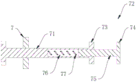
fig. 3 is a schematic structural view of the mount of the embodiment.
Reference numerals: 1. a frame; 2. a work table; 3. a column; 4. a main spindle box; 5. a clamping rod; 51. a slider; 52. a slide hole; 53. a groove; 54. a card slot; 6. a drive mechanism; 61. a drive rod; 62. a pull rod; 63. a support bar; 64. a pedal; 65. a support plate; 66. a spring; 7. a mounting seat; 71. mounting a rod; 72. positioning a plate; 73. a first plate body; 74. a second plate body; 75. adjusting a rod; 76. an adjustment hole; 77. an elastic member.
Detailed Description
The technical solution of the present invention will be clearly and completely described below with reference to the specific embodiments. It is obvious that the described embodiments are only some of the embodiments of the present invention, and not all of them. Based on the embodiments of the present invention, all other embodiments obtained by a person of ordinary skill in the art without creative efforts belong to the protection scope of the present invention.
As shown in fig. 1, a drilling machine includes a frame 1, a table 2 horizontally disposed on the frame 1, a column 3 vertically disposed on one side of the table 2, and a spindle box 4 disposed on the column 3.
When the drilling machine is used, a workpiece is placed on the workbench 2, then the workpiece is fixed, the drilling position of the workpiece is located under the spindle box 4, and then the spindle box 4 is used for controlling a drill bit on the workpiece to move downwards, so that the drilling processing of the workpiece is realized.
As shown in fig. 1, a pair of clamping rods 5 are arranged side by side on the table 2, and sliding blocks 51 are provided on both lower end surfaces of the clamping rods 5. A slide hole 52 through which the slide block 51 slides is bored on the table 2, and a drive mechanism 6 for controlling the pair of slide blocks 51 to move closer to or away from each other is provided below the table 2.
When the workpiece is clamped and fixed, the driving mechanism 6 is used for controlling the pair of sliding blocks 51 to approach each other, and at the moment, the sliding blocks 51 drive the clamping rods 5 to move synchronously and approach each other. After the clamping rods 5 clamp the workpiece, automatic centering and correction of the workpiece are achieved, the workpiece is located under the spindle box 4, and at the moment, the workpiece can be drilled by using a drill bit on the spindle box 4.
After drilling is finished, the driving mechanism 6 is used for controlling the pair of sliding blocks 51 to be away from each other, at the moment, the pair of sliding blocks 51 drive the pair of clamping rods 5 to be away from each other, fixing of the workpiece is released, then the workpiece is taken down, and drilling of the workpiece can be achieved.
As shown in fig. 1 and 2, a circular arc-shaped groove 53 is formed in the middle of the side where the pair of clamping rods 5 approach each other, and a locking groove 54 is formed in the side where the pair of clamping rods 5 approach each other in a penetrating manner along the length direction of the clamping rod, and the locking groove 54 is formed in a flaring shape.
When processing the work piece cylindrical and vertical form, can inlay the work piece and locate in recess 53, increase the area of contact of supporting rod 5 and work piece, realize the joint location of work piece, realize the stable centre gripping of work piece, guarantee the machining precision of work piece.
When a cylindrical and horizontal workpiece is processed, the workpiece can be embedded in the groove 54 of the clamping groove, so that the contact area between the clamping rod 5 and the workpiece is increased, the clamping and positioning of the workpiece are realized, the stable clamping of the workpiece is realized, and the processing precision of the workpiece is ensured.
As shown in fig. 1 and 2, the driving mechanism 6 includes a driving rod 61 horizontally disposed below the table 2, a pair of pull rods 62 are hinged to both ends of the driving rod 61, and upper ends of the pair of pull rods 62 are hinged to the pair of slide blocks 51.
As shown in fig. 1 and 2, a support rod 63 is vertically disposed at a middle position of the drive rod 61, a pedal 64 is disposed at a lower end of the support rod 63, a support plate 65 located below the pedal 64 is horizontally disposed on a side wall of the rack 1, and a spring 66 is disposed between the pedal 64 and the support plate 65.
When the pair of clamping rods 5 are controlled to approach each other, the pedal 64 is stepped down and the compression spring 66 is pressed to compress, at this time, the pedal 64 drives the support rod 63 and the driving rod 61 to synchronously move down, and the driving rod 61 drives the pull rod 62 to move down. At this time, the upper ends of the pair of tie rods 62 approach each other, and the slide block 51 and the clamping lever 5 are driven to approach each other, thereby controlling the clamping lever 5 to approach each other.
When the pair of clamping rods 5 are controlled to be away from each other, the pedal 64 is released, the spring 66 extends and drives the supporting rod 63 and the driving rod 61 to move upwards, the driving rod 61 drives the pull rod 62 to move upwards, meanwhile, the upper ends of the pull rods 62 are away from each other, the sliding block 51 and the clamping rods 5 are driven to be away from each other, and the control that the clamping rods 5 are away from each other is realized.
As shown in fig. 1 and 3, a mounting base 7 is provided at one end of the table 2, and a mounting rod 71 is horizontally slidably connected to the mounting base 7. The mounting rod 71 is screwed to the mounting base 7, and one end of the mounting rod 71 near the clamping rod 5 is provided with a positioning plate 72.
When a batch of workpieces are processed, one end of the workpiece is abutted by the positioning plate 72, so that the workpieces are positioned. When workpieces with different lengths are machined, the mounting rod 71 is rotated to drive the positioning plate 72 to move synchronously, so that the position of the positioning plate 72 is adjusted, and the batched workpieces are positioned quickly.
As shown in fig. 3, the positioning plate 72 includes a first plate 73 fixed to the mounting rod 71, and a second plate 74 is disposed on a side of the first plate 73 away from the mounting rod 71. An adjusting rod 75 is horizontally arranged on one side of the second plate body 74 close to the first plate body 73, an adjusting hole 76 for the adjusting rod 75 to slide and be embedded is horizontally arranged on the first plate body 73 and the second plate body 74, and an elastic part 77 is arranged between one end of the adjusting rod 75 departing from the second plate body 74 and the bottom wall of the adjusting hole 76.
When positioning the workpiece, the workpiece is driven to approach the second plate 74, and then the workpiece presses the second plate 74 to approach the first plate 73, the second plate 74 drives the adjusting rod 75 to move synchronously, and the elastic member 77 is pressed to compress. Until the second plate 74 abuts against the first plate 73, the positioning of the workpiece is achieved.
And after the workpiece is processed, the clamping rod 5 is separated from the workpiece, at this time, the elastic member 77 is bounced open, and the adjusting rod 75 and the second plate 74 are driven to move in reverse directions, so that the workpiece is automatically pushed out by the second plate 74, and the workpiece is automatically unloaded.
The working principle is as follows: when the drilling machine works, a workpiece is placed on the workbench 2, and then the treading type driving mechanism 6 is utilized to control the pair of sliding blocks 51 to drive the pair of clamping rods 5 to synchronously move and approach each other. And after the clamping rods 5 clamp the workpiece, the workpiece is positioned under the spindle box 4, and at the moment, the workpiece can be drilled by using the drill bit on the spindle box 4.
Claims (6)
1. The utility model provides a drilling machine, include frame (1), set up in workstation (2) in frame (1), vertical set up in stand (3) on workstation (2) with set up in headstock (4) on stand (3), its characterized in that: the clamping device is characterized in that a pair of clamping rods (5) are arranged on the workbench (2) side by side, sliding blocks (51) are arranged on the lower end faces of the two ends of each clamping rod (5), sliding holes (52) for the sliding blocks (51) to slide penetrate through the workbench (2), and driving mechanisms (6) for controlling the sliding blocks (51) to be close to or far away from each other are arranged below the workbench (2).
2. A drill press as claimed in claim 1, wherein: the driving mechanism (6) comprises a driving rod (61) horizontally arranged below the workbench (2), a pair of pull rods (62) are hinged to two ends of the driving rod (61), and the upper ends of the pair of pull rods (62) are hinged to the pair of sliding blocks (51); the middle position of actuating lever (61) is provided with bracing piece (63) vertically, the lower extreme of bracing piece (63) is provided with footboard (64), the lateral wall level of frame (1) is provided with and is located backup pad (65) of footboard (64) below, and footboard (64) with be provided with spring (66) between backup pad (65).
3. A drill press as claimed in claim 1, wherein: the middle part of one side of each pair of clamping rods (5) close to each other is provided with a circular arc-shaped groove (53).
4. A drill press as claimed in claim 3, wherein: clamping grooves (54) arranged along the length direction of the clamping rods (5) penetrate through the sides, close to each other, of the clamping rods, and the clamping grooves (54) are arranged in a flaring shape.
5. A drill press as claimed in claim 1, wherein: one end of the workbench (2) is provided with a mounting seat (7), the mounting seat (7) is horizontally and slidably connected with a mounting rod (71), the mounting rod (71) is in threaded connection with the mounting seat (7), and the mounting rod (71) is close to one end of the clamping rod (5) and is provided with a positioning plate (72).
6. The drill press of claim 5, wherein: locating plate (72) include with first plate body (73) that installation pole (71) are fixed mutually, first plate body (73) deviate from one side of installation pole (71) is provided with second plate body (74), second plate body (74) are close to one side level of first plate body (73) is provided with adjusts pole (75), first plate body (73) with second plate body (74) are improved level and are provided with the confession adjust pole (75) adjust regulation hole (76) of embedding that slides, and adjust pole (75) deviate from the one end of second plate body (74) with be provided with elastic component (77) between the diapire of regulation hole (76).
Priority Applications (1)
| Application Number | Priority Date | Filing Date | Title |
|---|---|---|---|
| CN202022144084.XU CN213052805U (en) | 2020-09-25 | 2020-09-25 | Drilling machine |
Applications Claiming Priority (1)
| Application Number | Priority Date | Filing Date | Title |
|---|---|---|---|
| CN202022144084.XU CN213052805U (en) | 2020-09-25 | 2020-09-25 | Drilling machine |
Publications (1)
| Publication Number | Publication Date |
|---|---|
| CN213052805U true CN213052805U (en) | 2021-04-27 |
Family
ID=75560645
Family Applications (1)
| Application Number | Title | Priority Date | Filing Date |
|---|---|---|---|
| CN202022144084.XU Expired - Fee Related CN213052805U (en) | 2020-09-25 | 2020-09-25 | Drilling machine |
Country Status (1)
| Country | Link |
|---|---|
| CN (1) | CN213052805U (en) |
Cited By (1)
| Publication number | Priority date | Publication date | Assignee | Title |
|---|---|---|---|---|
| CN113560631A (en) * | 2021-09-24 | 2021-10-29 | 天津赛象科技股份有限公司 | Hole opening device and method for flexible sleeve of carcass drum |
-
2020
- 2020-09-25 CN CN202022144084.XU patent/CN213052805U/en not_active Expired - Fee Related
Cited By (2)
| Publication number | Priority date | Publication date | Assignee | Title |
|---|---|---|---|---|
| CN113560631A (en) * | 2021-09-24 | 2021-10-29 | 天津赛象科技股份有限公司 | Hole opening device and method for flexible sleeve of carcass drum |
| CN113560631B (en) * | 2021-09-24 | 2022-07-26 | 天津赛象科技股份有限公司 | Hole opening method for flexible sleeve of carcass drum |
Similar Documents
| Publication | Publication Date | Title |
|---|---|---|
| CN219649266U (en) | Servo feeding clamping device of horizontal drilling machine and horizontal drilling machine | |
| CN210877599U (en) | A turning equipment of adjusting in convenient for machining | |
| CN209811275U (en) | High-efficiency radial drilling machine | |
| CN217702276U (en) | Gear shaft cover processing equipment | |
| CN112589539A (en) | Numerical control vertical and horizontal compound machine | |
| CN216097460U (en) | Tapping production line for linear cylindrical guide rail optical axis | |
| CN108620614B (en) | A CNC machine tool table | |
| CN111570843A (en) | Multi-degree-of-freedom drilling machine with automatic tool changing function | |
| CN110576201A (en) | multi-station feeding type drilling machine | |
| CN219725227U (en) | Processing equipment for hole of push pin triangle | |
| CN212917935U (en) | Reaming tapping machine | |
| CN213497277U (en) | Lathe work piece cuts off positioner | |
| CN215510098U (en) | Hydraulic auxiliary clamp suitable for longitudinal machining of special-shaped frame body workpiece | |
| CN213971496U (en) | Drilling equipment for drilling belt for processing PCB | |
| CN117884894A (en) | A hole processing equipment for push pin triangle | |
| CN117548705A (en) | Can improve machining efficiency's motor shaft production and processing frock clamp | |
| CN208961462U (en) | A new type of axle drilling and milling machine | |
| CN216542013U (en) | Manipulator material clamping device of numerical control drilling and grooving machine | |
| CN221494313U (en) | Rocker arm drilling machine workpiece clamp with accurate positioning function | |
| CN221582062U (en) | Drilling machine convenient to location | |
| CN216325230U (en) | Radial drill with position control function | |
| CN112894407A (en) | Multi-station inclined hole drilling clamp | |
| CN223762660U (en) | A special processing equipment for caliper brackets | |
| CN223811569U (en) | Multi-station adjustable drilling machine | |
| CN219152176U (en) | Drilling and dotting mechanism of vertical drilling machine |
Legal Events
| Date | Code | Title | Description |
|---|---|---|---|
| GR01 | Patent grant | ||
| GR01 | Patent grant | ||
| CF01 | Termination of patent right due to non-payment of annual fee | ||
| CF01 | Termination of patent right due to non-payment of annual fee |
Granted publication date: 20210427 |