CN213033905U - Laser cutting machine with loading attachment - Google Patents
Laser cutting machine with loading attachment Download PDFInfo
- Publication number
- CN213033905U CN213033905U CN202021538690.3U CN202021538690U CN213033905U CN 213033905 U CN213033905 U CN 213033905U CN 202021538690 U CN202021538690 U CN 202021538690U CN 213033905 U CN213033905 U CN 213033905U
- Authority
- CN
- China
- Prior art keywords
- plate
- fixed
- cutting machine
- laser cutting
- hole
- Prior art date
- Legal status (The legal status is an assumption and is not a legal conclusion. Google has not performed a legal analysis and makes no representation as to the accuracy of the status listed.)
- Active
Links
Images


Abstract
The utility model belongs to the technical field of loading attachment, especially, a laser cutting machine with loading attachment, the on-line screen storage device comprises a base, the top fixed mounting of base has the install bin, and fixed mounting has the fixed plate and places the board on the bottom inner wall of install bin, and the fixed plate is located the below of placing the board and the fixed plate and places the board direct fixed mounting have same slide towards the fixed plate slope, the install bin is close to one side of placing the board and sets up the feed opening that is located the board top, and feed opening internal fixation has the lower flitch towards placing the board slope, the top of placing the board has seted up the slip hole, and the install bin is close to one side of slip hole and has seted up the through-hole on the horizontal direction, and movable rod that movable mounting is located the. The utility model discloses simple structure, convenient to use, be convenient for carry out the material loading to laser cutting machine and be convenient for carry on spacing fixedly to the panel after the material loading, it is automatic strong.
Description
Technical Field
The utility model relates to a loading attachment technical field especially relates to a laser cutting machine with loading attachment.
Background
The laser cutting operation in-process has most cutting material to be panel class material, uses fork truck or crane material loading usually among the current material loading technique, and such material loading is not only efficient not high but also application fork truck or crane still can waste the usable floor area in workshop, is unfavorable for workshop management, and the more important positioning problem that can't solve the material loading among the current material loading technique carries out final location by the manual work usually, accurate inadequately.
The patent with the application number of 201820377947.8 relates to a laser cutting machine feeding device, which comprises a laser cutting machine body, a travelling crane, a supporting structure, a steel wire rope, a vacuum manufacturing device, a sucker seat and a sucker, wherein the travelling crane is connected with the steel wire rope, and the travelling crane is arranged on the supporting structure; the steel wire rope is connected with a sucker seat provided with a sucker; the vacuum manufacturing device is arranged on the sucker seat, the feeding device of the laser cutting machine further comprises a positioning structure and a positioning ring, and the positioning ring is arranged on the laser cutting machine body; the positioning structure comprises an adjusting arm, a rotating shaft and a positioning arm; the positioning structures are arranged on two sides of the sucker seat; the adjusting arm is connected with the sucker seat; the positioning arm can rotate by depending on the rotating shaft to form an angle of 180 degrees or 90 degrees with the adjusting arm; the locator arm can be inserted into the locator ring. Through research, the process of the feeding device in the patent is too complex, and the positioning is not convenient enough.
SUMMERY OF THE UTILITY MODEL
The utility model aims at solving the defects existing in the prior art and providing a laser cutting machine with a feeding device.
In order to achieve the above purpose, the utility model adopts the following technical scheme:
a laser cutting machine with a feeding device comprises a base, wherein an installation box is fixedly installed at the top of the base, a fixed plate and a placing plate are fixedly installed on the inner wall of the bottom of the installation box, the fixed plate is positioned below the placing plate, a sliding plate which inclines towards the fixed plate is directly and fixedly installed on the fixed plate and the placing plate, a blanking hole which is positioned above the placing plate is formed in one side, close to the placing plate, of the installation box, a blanking plate which inclines towards the placing plate is fixedly installed in the blanking hole, a sliding hole is formed in the top of the placing plate, a through hole is formed in one side, close to the sliding hole, of the installation box in the horizontal direction, a movable rod which is positioned below the sliding hole is movably installed in the through hole, two ends of the movable rod extend out of the through hole, a hit plate which is positioned outside the installation box is fixedly installed, the output shaft of the rotating motor is fixedly sleeved with a cam matched with the beaten plate.
Preferably, the top fixed mounting of movable rod has the one end that is located two connecting rods of install bin, and the other end of two connecting rods all extends to in the sliding hole and equal fixed mounting has rubber friction soon.
Preferably, the standing groove has been seted up at the top of fixed plate, the both sides of standing groove all along the horizontal direction on set up with the standing groove be linked together change the hole, change downthehole all to rotate and install the lead screw guide pin bushing, the equal screw thread of the one end that two lead screw guide pins are close to each other has cup jointed the lead screw, the equal symmetrical fixed mounting of one end that two lead screws are close to each other has L type clamp plate, the other end of two lead screw guide pins all extends to the fixed plate and outer and fixed the cup joint has the gear, the equal fixed mounting in output shaft both sides of hydraulic cylinder has fixed horizontal pole, and the equal fixed mounting in bottom of two fixed horizontal poles has the.
Preferably, the thread directions of the two screw rods are opposite.
Preferably, the bottom of the placing groove is provided with a sliding groove in the horizontal direction, two sliding blocks are arranged in the sliding groove in a sliding mode, and the two sliding blocks are fixedly connected with the bottoms of the two L-shaped clamping plates respectively.
Preferably, the movable rod is fixedly sleeved with a fixed block, one side of the fixed block, which is close to the cam, is fixedly provided with one end of each of the two springs, and the other end of each of the two springs is fixed on the inner wall of the installation box.
In the utility model, the laser cutting machine with the feeding device drives the rotation of the cam by starting the rotating motor, the hit striking plate is hit by the cam continuously, the movable rod is driven to move back and forth left and right by the action of the spring, then the two rubber friction blocks are driven to move back and forth left and right, the plate slides down to the placing plate by placing the plate on the blanking plate, when the two rubber friction blocks move left, the plate is convenient to be pushed to move left by the contact between the two rubber friction blocks and the bottom of the plate, the plate is pushed to the upper part by pushing the sliding plate to slide down to the placing groove on the fixing plate by the sliding plate, then the laser cutter and the two racks are driven to move down by starting the hydraulic cylinder, the two racks drive the rotation of the two gears in the process of moving down, the lead screw drives the rotation of the guide sleeve, because the screw thread direction of two lead screws sets up for opposite, so when two lead screw guide pin bushings rotate the in-process, drive two lead screws and remove in opposite directions, drive two L type clamp plates then and remove in opposite directions, can press from both sides tightly panel through two L type clamp plates then, when pressing from both sides tight the completion, the laser cutter just falls suitable height, can press from both sides tight cutting to panel. The utility model discloses simple structure, convenient to use, be convenient for carry out the material loading to laser cutting machine and be convenient for carry on spacing fixedly to the panel after the material loading, it is automatic strong.
Drawings
Fig. 1 is a schematic structural diagram of a laser cutting machine with a feeding device according to the present invention;
fig. 2 is a schematic structural diagram of a part a of a laser cutting machine with a feeding device according to the present invention;
fig. 3 is a schematic structural diagram of a part B of the laser cutting machine with the feeding device provided by the present invention.
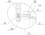
In the figure: the device comprises a base 1, a placing groove 2, a fixing plate 3, a sliding plate 4, a rotating motor 5, a cam 6, a hit plate 7, a placing plate 8, a blanking plate 9, a sliding hole 10, an L-shaped clamping plate 11, a rubber friction block 12, a hydraulic oil cylinder 13, a laser cutter 14, a rack 15, a mounting box 16, a spring 17, a movable rod 18, a fixing block 19, a lead screw guide sleeve 20, a gear 21 and a lead screw 22.
Detailed Description
The technical solutions in the embodiments of the present invention will be described clearly and completely with reference to the accompanying drawings in the embodiments of the present invention, and it is obvious that the described embodiments are only some embodiments of the present invention, not all embodiments.
Example one
Referring to fig. 1-3, a laser cutting machine with a feeding device comprises a base 1, a mounting box 16 is fixedly mounted on the top of the base 1, a fixed plate 3 and a placing plate 8 are fixedly mounted on the inner wall of the bottom of the mounting box 16, the fixed plate 3 is positioned below the placing plate 8, the fixed plate 3 and the placing plate 8 are directly and fixedly mounted with a sliding plate 4 which inclines towards the fixed plate 3, one side of the mounting box 16 close to the placing plate 8 is provided with a discharging hole positioned above the placing plate 8, a discharging plate 9 which inclines towards the placing plate 8 is fixedly mounted in the discharging hole, the top of the placing plate 8 is provided with a sliding hole 10, one side of the mounting box 16 close to the sliding hole 10 is provided with a through hole along the horizontal direction, a movable rod 18 positioned below the sliding hole 10 is movably mounted in the through hole, two ends of the movable rod 18 both extend out of the through hole, and one end of the movable rod, one side of the base 1 close to the beaten plate 7 is fixedly provided with a rotating motor 5, and an output shaft of the rotating motor 5 is fixedly sleeved with a cam 6 matched with the beaten plate 7.
Example two
The utility model discloses in, the top fixed mounting of movable rod 18 has the one end that is located two connecting rods of install bin 16, and the other end of two connecting rods all extends to in the sliding hole 10 and equal fixed mounting has rubber friction fast 12, and when the in-process that two rubber friction blocks 12 moved left, think the contact through two rubber friction blocks 12 and panel bottom, be convenient for promote panel and move left, with panel sliding plate to 4 on, panel is in through the standing groove 2 that 4 gliding fixed plates 3 on of slide.
The utility model discloses in, standing groove 2 has been seted up at the top of fixed plate 3, standing groove 2's both sides all follow the horizontal direction on set up with standing groove 2 be linked together change the hole, change the downthehole equal rotation and install lead screw guide pin bushing 20, the equal screw thread of one end that two lead screw guide pin bushings 20 are close to each other has cup jointed lead screw 22, the equal symmetrical fixed mounting of one end that two lead screws 22 are close to each other has L type clamp plate 11, two lead screw guide pin bushing 20's the other end all extends to fixed plate 3 outer and fixed the cup joint has gear 21, the equal fixed mounting in output shaft both sides of hydraulic cylinder 13 has fixed horizontal pole, the equal fixed mounting in bottom of two fixed horizontal poles has rack 15, two rack 15 mesh with corresponding gear 21 respectively, two rack 15 are at the in-process of downshifting, drive two gears 21's.
The utility model discloses in, two lead screws 22's screw thread direction sets up for opposite, because two lead screws 22's screw thread direction sets up for opposite, so rotate the in-process when two lead screw guide pin bushings 20, drive two lead screws 22 and remove in opposite directions, drive two L type clamp plates 11 and remove in opposite directions then, can press from both sides tightly to panel through two L type clamp plates 11 then.
The utility model discloses in, the spout has been seted up on the horizontal direction in the bottom of standing groove 2, and slidable mounting has two sliders in the spout, two sliders respectively with the bottom fixed connection of two L type clamp plates 11, through the removal of spout and slider two L type clamp plates 11 of being convenient for.
The utility model discloses in, fixed block 19 has been cup jointed to the last fixed block that has cup jointed of movable rod 18, and fixed block 19 is close to the one end of two springs 17 of one side fixed mounting of cam 6, and the other end of spring 17 all fixes on the inner wall of install bin 16, through the reset of the movable rod 18 of being convenient for of spring 17.
In the utility model, firstly, the rotating motor 5 is started to drive the cam 6 to rotate, the cam 6 is used to continuously hit the hit plate 7, the movable rod 18 is driven to move back and forth left and right under the action of the spring 17, then the two rubber friction blocks 12 are driven to move back and forth left and right, the plate is placed on the blanking plate 9, the plate slides down onto the placing plate 8 through the blanking plate 9, when the two rubber friction blocks 12 move left, the plate is convenient to be pushed to move left through the contact between the two rubber friction blocks 12 and the bottom of the plate, the plate is pushed to slide to the plate 4, the plate slides down into the placing groove 2 on the fixed plate 3 through the sliding plate 4, then the hydraulic cylinder 13 is started to drive the laser cutter 14 and the two racks 15 to move down, the two racks 15 drive the two gears 21 to rotate in the process of moving down, the gears 21 drive the guide sleeve 20 to rotate, because the screw thread direction of two lead screws 22 sets up for opposite, so rotate the in-process when two lead screw guide pin bushings 20, drive two lead screws 22 and remove in opposite directions, drive two L type clamp plates 11 and remove in opposite directions then, can press from both sides tightly panel through two L type clamp plates 11 then, when pressing from both sides tight the completion, laser cutter 14 just drops to suitable height, can press from both sides tight cutting to panel. The utility model discloses simple structure, convenient to use, be convenient for carry out the material loading to laser cutting machine and be convenient for carry on spacing fixedly to the panel after the material loading, it is automatic strong.
The above, only be the concrete implementation of the preferred embodiment of the present invention, but the protection scope of the present invention is not limited thereto, and any person skilled in the art is in the technical scope of the present invention, according to the technical solution of the present invention and the utility model, the concept of which is equivalent to replace or change, should be covered within the protection scope of the present invention.
Claims (6)
1. A laser cutting machine with a feeding device comprises a base (1) and is characterized in that a mounting box (16) is fixedly mounted at the top of the base (1), a fixed plate (3) and a placing plate (8) are fixedly mounted on the inner wall of the bottom of the mounting box (16), the fixed plate (3) is positioned below the placing plate (8), a sliding plate (4) which inclines towards the fixed plate (3) is directly and fixedly mounted on the fixed plate (3) and the placing plate (8), a blanking hole which is positioned above the placing plate (8) is formed in one side, close to the placing plate (8), of the mounting box (16), a blanking plate (9) which inclines towards the placing plate (8) is fixedly mounted in the blanking hole, a sliding hole (10) is formed in the top of the placing plate (8), a through hole is formed in the horizontal direction in one side, close to the sliding hole (10), of the mounting box (16), and a movable rod (18) which is positioned below the sliding hole (10) is movably mounted, both ends of the movable rod (18) all extend to the through hole and one end of the movable rod is fixedly provided with a hit plate (7) positioned outside the installation box (16), one side of the base (1) close to the hit plate (7) is fixedly provided with a rotating motor (5), and an output shaft of the rotating motor (5) is fixedly sleeved with a cam (6) matched with the hit plate (7).
2. The laser cutting machine with the feeding device according to claim 1, characterized in that the top of the movable rod (18) is fixedly provided with one end of two connecting rods in the mounting box (16), the other ends of the two connecting rods both extend into the sliding hole (10) and are fixedly provided with rubber friction blocks (12).
3. Laser cutting machine with loading device according to claim 1, standing groove (2) have been seted up at the top of fixed plate (3), the both sides of standing groove (2) are all followed and are seted up the commentaries on classics hole that is linked together with standing groove (2) on the horizontal direction, downthehole equal rotation of commentaries on classics installs lead screw guide pin bushing (20), the equal screw thread of one end that two lead screw guide pin bushings (20) are close to each other has cup jointed lead screw (22), the equal symmetrical fixed mounting in one end that two lead screw (22) are close to each other has L type clamp plate (11), the other end of two lead screw guide pin bushings (20) all extends to fixed plate (3) outer and fixed cover and has connect gear (21), the equal fixed mounting in output shaft both sides of hydraulic cylinder (13) has fixed horizontal pole, the equal fixed mounting in bottom of two fixed horizontal poles has rack (15.
4. A laser cutting machine with a feeding device according to claim 3, characterized in that the thread directions of the two screw rods (22) are opposite.
5. The laser cutting machine with the feeding device according to claim 3, wherein a sliding groove is formed in the bottom of the placing groove (2) along the horizontal direction, two sliding blocks are slidably mounted in the sliding groove, and the two sliding blocks are respectively and fixedly connected with the bottoms of the two L-shaped clamping plates (11).
6. The laser cutting machine with the feeding device according to claim 1, wherein the movable rod (18) is fixedly sleeved with a fixed block (19), one side of the fixed block (19) close to the cam (6) is fixedly provided with one end of two springs (17), and the other end of each spring (17) is fixed on the inner wall of the mounting box (16).
Priority Applications (1)
| Application Number | Priority Date | Filing Date | Title |
|---|---|---|---|
| CN202021538690.3U CN213033905U (en) | 2020-07-30 | 2020-07-30 | Laser cutting machine with loading attachment |
Applications Claiming Priority (1)
| Application Number | Priority Date | Filing Date | Title |
|---|---|---|---|
| CN202021538690.3U CN213033905U (en) | 2020-07-30 | 2020-07-30 | Laser cutting machine with loading attachment |
Publications (1)
| Publication Number | Publication Date |
|---|---|
| CN213033905U true CN213033905U (en) | 2021-04-23 |
Family
ID=75529120
Family Applications (1)
| Application Number | Title | Priority Date | Filing Date |
|---|---|---|---|
| CN202021538690.3U Active CN213033905U (en) | 2020-07-30 | 2020-07-30 | Laser cutting machine with loading attachment |
Country Status (1)
| Country | Link |
|---|---|
| CN (1) | CN213033905U (en) |
-
2020
- 2020-07-30 CN CN202021538690.3U patent/CN213033905U/en active Active
Similar Documents
| Publication | Publication Date | Title |
|---|---|---|
| CN205342675U (en) | Cantilever lathe with tool magazine group | |
| CN209578768U (en) | The central spindle axle sleeve of potentiometer or encoder assembles equipment | |
| CN213033905U (en) | Laser cutting machine with loading attachment | |
| CN109746675A (en) | The central spindle axle sleeve of potentiometer or encoder assembles equipment | |
| CN111085708B (en) | Self-floating automobile part processing and conveying line | |
| CN218050042U (en) | New forms of energy fill electric pile sheet metal component bending device | |
| CN215239512U (en) | Guide swinging type manual tool changing mechanism applied to tool magazine of horizontal machining center | |
| CN212793153U (en) | Positioner is used in power takeoff spare part processing | |
| CN210189172U (en) | Long drill tail screw drill tail processing mechanism | |
| CN210849389U (en) | Machine tool with cooling and recycling functions | |
| CN210943862U (en) | Automatic briquetting unloading machine | |
| CN215142347U (en) | Test equipment is used in production of cell-phone charger | |
| CN220181487U (en) | Wire harness wire stripping machine | |
| CN109544792A (en) | A kind of container automatic device for taking out | |
| CN220612548U (en) | Screw processing device | |
| CN110640367A (en) | Circuit box welding robot and process | |
| CN215620055U (en) | Plastic accessory ultrasonic welding device | |
| CN217996676U (en) | Intelligent substation communication equipment installs auxiliary device | |
| CN211101697U (en) | Manufacturing equipment for tension wheel | |
| CN220614010U (en) | Multifunctional manipulator | |
| CN217776117U (en) | Automatic super capacitor assembling machine | |
| CN215788478U (en) | Manipulator translation device for composite machining of multiple machine tools | |
| CN215280571U (en) | Automatic rapid welding equipment for power distribution cabinet partition plate | |
| CN219466118U (en) | Mechanical part processing table convenient to use | |
| CN215469832U (en) | Mobile manipulator device for processing semi-solid products |
Legal Events
| Date | Code | Title | Description |
|---|---|---|---|
| GR01 | Patent grant | ||
| GR01 | Patent grant |