CN213032810U - Aluminum alloy section powder spraying device - Google Patents
Aluminum alloy section powder spraying device Download PDFInfo
- Publication number
- CN213032810U CN213032810U CN202021567489.8U CN202021567489U CN213032810U CN 213032810 U CN213032810 U CN 213032810U CN 202021567489 U CN202021567489 U CN 202021567489U CN 213032810 U CN213032810 U CN 213032810U
- Authority
- CN
- China
- Prior art keywords
- aluminum alloy
- block
- spraying frame
- spraying
- sliding plate
- Prior art date
- Legal status (The legal status is an assumption and is not a legal conclusion. Google has not performed a legal analysis and makes no representation as to the accuracy of the status listed.)
- Expired - Fee Related
Links
- 238000005507 spraying Methods 0.000 title claims abstract description 72
- 239000000843 powder Substances 0.000 title claims abstract description 42
- 229910000838 Al alloy Inorganic materials 0.000 title claims abstract description 40
- 230000007246 mechanism Effects 0.000 claims abstract description 19
- 238000001125 extrusion Methods 0.000 claims abstract description 15
- 239000007921 spray Substances 0.000 claims description 19
- 238000003860 storage Methods 0.000 claims description 14
- 230000005540 biological transmission Effects 0.000 claims description 9
- 239000000463 material Substances 0.000 claims description 5
- 230000000903 blocking effect Effects 0.000 claims description 4
- 238000000034 method Methods 0.000 description 10
- 230000008569 process Effects 0.000 description 9
- 238000005516 engineering process Methods 0.000 description 4
- 238000003466 welding Methods 0.000 description 3
- 230000009286 beneficial effect Effects 0.000 description 2
- 238000012986 modification Methods 0.000 description 2
- 230000004048 modification Effects 0.000 description 2
- 239000002699 waste material Substances 0.000 description 2
- CWYNVVGOOAEACU-UHFFFAOYSA-N Fe2+ Chemical compound [Fe+2] CWYNVVGOOAEACU-UHFFFAOYSA-N 0.000 description 1
- 238000005034 decoration Methods 0.000 description 1
- 238000010586 diagram Methods 0.000 description 1
- 238000004134 energy conservation Methods 0.000 description 1
- 230000007613 environmental effect Effects 0.000 description 1
- 238000004519 manufacturing process Methods 0.000 description 1
- 229910052751 metal Inorganic materials 0.000 description 1
- 239000002184 metal Substances 0.000 description 1
- 239000000126 substance Substances 0.000 description 1
Images


Landscapes
- Nozzles (AREA)
Abstract
The utility model provides an aluminum alloy ex-trusions powder spraying device, including spraying frame and unable adjustment base, the bottom of spraying frame is fixed with unable adjustment base, unable adjustment base's one end is provided with the storing groove, unable adjustment base's the other end is provided with the aggregate bin. The utility model discloses in, through the sliding plate with adjustable both sides are all about the inside setting of spraying frame, and the inboard accessible driving motor driven extrusion piece of sliding plate, not only can fix aluminum alloy workpiece through the extrusion piece, still can drive aluminum alloy workpiece through driving motor simultaneously and rotate, set up the shower nozzle on vertical moving mechanism simultaneously, can drive the shower nozzle through ball and reciprocate, drive the actuating lever then through miniature cylinder and drive the toothed disc rotation, can drive the shower nozzle rotation, angle regulation, consequently adopt such structure can be with the more comprehensive spraying that carries on of powder.
Description
Technical Field
The utility model relates to an aluminum alloy field especially relates to an aluminum alloy ex-trusions powder spraying device.
Background
Aluminum alloy sections are the most widely used non-ferrous metal structural materials in industry. The aluminum alloy section is used in aviation, aerospace, automobile, machinery manufacturing, ships, building and decoration. And has been used in a large number of applications in the chemical industry. With the rapid development of scientific technology and industrial economy in recent years, the demand for aluminum alloy welded structural parts is increasing, and the weldability research of aluminum alloy is also deepened. The wide application of the aluminum alloy promotes the development of the aluminum alloy welding technology, and meanwhile, the development of the welding technology expands the application field of the aluminum alloy, so that the aluminum alloy welding technology is becoming one of the hot spots of research.
Aluminum alloy ex-trusions need carry out the powder spraying according to user's needs in the course of working to the spraying becomes user's required pattern and required colour, but the aluminum alloy still has some weak points at the in-process of carrying out the powder spraying, and traditional work piece is fixed comparatively simply with the work piece carrying out the general shower nozzle of spraying process, and the work piece is adjusted not nimble enough, and the shower nozzle is difficult for adjusting, leads to work piece spraying inefficiency for this reason, and the spraying quality is low, consequently the utility model provides an aluminum alloy ex-trusions powder spraying device solves above-mentioned problem.
SUMMERY OF THE UTILITY MODEL
An object of the utility model is to provide an aluminum alloy ex-trusions powder spraying device to solve above-mentioned technical problem.
The utility model discloses a solve above-mentioned technical problem, adopt following technical scheme to realize: the utility model provides an aluminum alloy ex-trusions powder spraying device, includes spraying frame and unable adjustment base, its characterized in that: a fixed base is fixed at the bottom of the spraying frame, a storage groove is formed in one end of the fixed base, and a material collecting bin is arranged at the other end of the fixed base;
the upper side and the lower side of the interior of the spraying frame are both connected with sliding plates through hydraulic telescopic rods, one side of each sliding plate, which is close to the middle position of the spraying frame, is provided with an extrusion block, the extrusion block penetrates through the sliding plates through a rotating shaft and is in transmission connection with a driving motor positioned on the other side of the sliding plate, the middle position of one side of the spraying frame is provided with a sliding groove, and the middle position of the other side of the spraying frame is provided with a;
a blocking rod is fixed on one side of the top of the storage tank, a ball screw is arranged on one side, close to the blocking rod, of the spraying frame, the bottom of the ball screw is in transmission connection with a driving motor, a vertical moving mechanism is in threaded transmission on the outer side of the ball screw, a venturi powder pump is arranged on the top of the storage tank, the inlet of the venturi powder pump is communicated into the storage tank through a communicating pipe, the outlet of the venturi powder pump is connected with a spray head through an elastic pipe, the spray head extends into the spraying frame through a sliding groove, and the spray head is fixed on the vertical moving mechanism;
the discharge port is connected to an air extractor through a communicating pipe, and the air extractor is communicated to the aggregate bin through the communicating pipe.
Preferably, the extrusion block is made of rubber.
Preferably, the two sides of the sliding plate are movably provided with rollers, and the rollers are attached to the inner side wall of the spraying frame.
Preferably, the sliding groove and the center of the discharge hole are positioned on the same horizontal line.
Preferably, the vertical moving mechanism comprises a spiral moving block, a positioning block, a gear disc and a limiting block, the spiral moving block is sleeved on the outer side of the ball screw in a threaded manner, the gear disc is movably connected to one side of the spiral moving block, the limiting block is arranged on the outer side of the gear disc, the spray head penetrates through the limiting block, and the positioning block penetrates through the middle position of the outer side of the limiting block.
Preferably, a gear block is arranged on the outer side of the gear disc, a driving rod is slidably connected to one side of the spiral moving block and above the gear disc, the inner side of the driving rod is slidably connected to a sliding groove formed in the spiral moving block, a gear is arranged at the bottom of the driving rod, the driving rod is meshed with the gear disc and is connected with the gear disc, a micro cylinder is arranged on one side of the spiral moving block, and the micro cylinder is connected to the driving rod through a telescopic rod.
Compared with the prior art, the utility model provides a pair of aluminum alloy ex-trusions powder spraying device has following beneficial effect:
the utility model provides an aluminum alloy section powder spraying device, firstly, through setting up the sliding plate with both sides adjustable up and down in the spraying frame, and the inner side of the sliding plate can be fixed to the aluminum alloy workpiece through the extrusion block driven by the driving motor, and simultaneously, the aluminum alloy workpiece can be driven to rotate through the driving motor, and the nozzle is set on the vertical moving mechanism, the nozzle can be driven to move up and down through the ball screw, the driving rod is driven by the micro-cylinder to drive the gear disc to rotate, thereby the nozzle can be driven to rotate, the angle can be adjusted, therefore, the powder can be sprayed more comprehensively by adopting the structure, the more uniform and complete spraying of the aluminum alloy workpiece is ensured, the working quality is improved, the working efficiency is accelerated, secondly, one side of the spraying frame 1 is also provided with a discharge port, an air extractor and a, the air pump can pump out the redundant powder generated in the spraying frame 1, so that the powder is prevented from falling, the resource waste is avoided, and the energy conservation and the environmental protection are realized.
Drawings
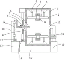
Fig. 1 is a schematic structural view of an aluminum alloy profile powder spraying device of the present invention;
fig. 2 is a schematic structural view of the vertical moving mechanism of the present invention;
fig. 3 is a top view of the vertical moving mechanism of the present invention;
reference numerals: 1. spraying a frame; 2. a roller; 3. a sliding plate; 4. a drive motor; 5. a hydraulic telescopic rod; 6. a spray head; 7. a ball screw; 8. a vertical moving mechanism; 81. a spiral moving block; 82. a drive rod; 83. a chute; 84. positioning blocks; 85. a gear plate; 86. a limiting block; 87. a telescopic rod; 88. a micro cylinder; 9. an elastic tube; 10. a gear lever; 11. a sliding groove; 12. a venturi powder pump; 13. a storage tank; 14. a drive motor; 15. a fixed base; 16. a discharge port; 17. extruding the block; 18. an air extractor; 19. a material collecting bin.
Detailed Description
In order to make the technical means, the creation features, the achievement purposes and the functions of the present invention easy to understand, the present invention will be further explained below with reference to the following embodiments and the accompanying drawings, but the following embodiments are only the preferred embodiments of the present invention, and not all embodiments are included. Based on the embodiments in the implementation, other embodiments obtained by those skilled in the art without any creative efforts belong to the protection scope of the present invention.
The following describes an embodiment of the present invention with reference to the accompanying drawings, please refer to fig. 1, fig. 2 and fig. 3, wherein fig. 1 is a schematic structural diagram of an aluminum alloy profile powder spraying apparatus of the present invention; fig. 2 is a schematic structural view of the vertical moving mechanism of the present invention; fig. 3 is a top view of the vertical moving mechanism of the present invention.
In the specific implementation process, as shown in fig. 1-3, an aluminum alloy section powder spraying device comprises a spraying frame 1 and a fixing base 15, and is characterized in that: a fixed base 15 is fixed at the bottom of the spraying frame 1, a storage groove 13 is arranged at one end of the fixed base 15, and a material collecting bin 19 is arranged at the other end of the fixed base 15; the upper side and the lower side of the interior of the spraying frame 1 are both connected with a sliding plate 3 through hydraulic telescopic rods 5, one side of the sliding plate 3 close to the middle position of the spraying frame 1 is provided with an extrusion block 17, wherein the extrusion block 17 penetrates through the sliding plate 3 through a rotating shaft and is in transmission connection with a driving motor 4 positioned on the other side of the sliding plate 3, the middle position of one side of the spraying frame 1 is provided with a sliding groove 11, and the middle position of the other side of the spraying frame 1 is provided with a; a stop rod 10 is fixed on one side of the top of a storage tank 13, a ball screw 7 is arranged on one side, close to the stop rod 10, of a spraying frame 1, wherein the bottom of the ball screw 7 is in transmission connection with a driving motor 14, a vertical moving mechanism 8 is in threaded transmission on the outer side of the ball screw 7, a venturi powder pump 12 is arranged on the top of the storage tank 13, an inlet of the venturi powder pump 12 is communicated into the storage tank 13 through a communicating pipe, an outlet of the venturi powder pump 12 is connected with a spray head 6 through an elastic pipe 9, the spray head 6 extends into the spraying frame 1 through a sliding groove 11, and the spray head 6 is fixed on the vertical moving mechanism 8; the discharge opening 16 is connected to an air extractor 18 via a communicating pipe, the air extractor 18 in turn being connected to a collecting bin 19 via a communicating pipe.
In the specific implementation, as shown in fig. 1, the extrusion block 17 is made of rubber.
In the specific implementation process, as shown in fig. 1, rollers 2 are movably disposed on both sides of the sliding plate 3, wherein the rollers 2 are attached to the inner side wall of the spraying frame 1.
In the specific implementation process, as shown in fig. 1, the center positions of the sliding groove 11 and the discharge hole 16 are on the same horizontal line.
In the specific implementation process, as shown in fig. 2-3, the vertical moving mechanism 8 includes a spiral moving block 81, a positioning block 84, a gear disc 85 and a limiting block 86, the spiral moving block 81 is sleeved outside the ball screw 7, one side of the spiral moving block 81 is movably connected with the gear disc 85, the limiting block 86 is arranged outside the gear disc 85, the spray head 6 penetrates through the inside of the limiting block 86, and the positioning block 84 penetrates through the middle position of the outside of the limiting block 86.
In a specific implementation process, as shown in fig. 2-3, the vertical moving mechanism 8 includes a spiral moving block 81, a positioning block 84, a gear disc 85 and a limiting block 86, the spiral moving block 81 is in threaded sleeve connection with the outer side of the ball screw 7, one side of the spiral moving block 81 is movably connected with the gear disc 85, the outer side of the gear disc 85 is provided with the limiting block 86, the spray head 6 penetrates through the inside of the limiting block 86, and the positioning block 84 penetrates through the middle position of the outer side of the limiting block 86; the outside of toothed disc 85 is provided with the gear piece, and one side of spiral moving block 81 and the top sliding connection that is located toothed disc 85 have a drive lever 82, and wherein the inboard sliding connection of drive lever 82 is in seting up the spout 83 on spiral moving block 81, and the bottom of drive lever 82 is provided with the gear, and drive lever 82 is connected with toothed disc 85 meshing, and one side of spiral moving block 81 is provided with micro cylinder 88, and micro cylinder 88 is connected to on drive lever 82 through telescopic link 87.
The working principle of the utility model is as follows: firstly, an aluminum alloy workpiece is prevented from being in the spraying frame 1, the positions of the upper sliding plate 3 and the lower sliding plate 3 are adjusted through the hydraulic telescopic rod 5, so that the workpiece is extruded and fixed through the extrusion blocks 17 on the two sliding plates 3, when the workpiece is sprayed, powder in the storage groove 13 is firstly undetermined into the spray head 6 through the Venturi powder pump 12 and then sprayed onto the workpiece in the spraying frame 1 through the spray head 6, in the process of spraying, the driving motor 14 is controlled to drive the ball screw 7 to rotate, the ball screw 7 can drive the vertical moving mechanism 8 to move up and down when rotating, and further drive the spray head 6 to move up and down, corresponding adjustment can be carried out according to the position of the workpiece, meanwhile, the micro cylinder 88 drives the driving rod 82 to move, the driving rod 82 is meshed with the limiting block 86 and can drive the limiting block 86 to rotate, and the rotation angle is-45 degrees to 45 degrees, so that the workpiece can be sprayed in all aspects by adjusting the angle of the spray head 6 at the position where the spray head can not be sprayed in the horizontal direction, and the air extractor 18 works in the spraying process or after the spraying process, so that the rest powder in the spraying frame 1 can be pumped into the collecting bin 19 for collection.
Compared with the prior art, the utility model provides a pair of aluminum alloy ex-trusions powder spraying device has following beneficial effect:
the utility model provides an aluminum alloy ex-trusions powder spraying device, firstly, sliding plate 3 with both sides all adjustable about through setting up in spraying frame 1 inside, and sliding plate 3's inboard accessible actuating motor 4 driven extrusion piece 17, not only can fix the aluminum alloy work piece through extrusion piece 17, still can drive the aluminum alloy work piece through actuating motor 4 simultaneously and rotate, set up shower nozzle 6 on vertical moving mechanism 8 simultaneously, can drive shower nozzle 6 through ball 7 and reciprocate, drive actuating lever 82 then through miniature cylinder 88 and drive toothed disc 85 and rotate, can drive shower nozzle 6 and rotate, angle regulation, consequently, adopt such structure can be with the more comprehensive spraying of powder, guarantee the more even of aluminum alloy work piece spraying, it is complete, the work quality is improved, and the work efficiency is accelerated, secondly, still be provided with discharge gate 16 in one side of spraying frame 1, Air extractor 18 and collecting bin 19 can take out the unnecessary powder that produces in the frame 1 of spraying through air extractor 18, prevents that the powder from dropping, causes the waste of resource, and is energy-concerving and environment-protective.
The foregoing shows and describes the general principles, essential features, and advantages of the invention. It should be understood by those skilled in the art that the present invention is not limited by the above embodiments, and the description in the above embodiments and the description is only preferred examples of the present invention, and is not intended to limit the present invention, and that the present invention can have various changes and modifications without departing from the spirit and scope of the present invention, and these changes and modifications all fall into the scope of the claimed invention. The scope of the invention is defined by the appended claims and equivalents thereof.
Claims (6)
1. The utility model provides an aluminum alloy ex-trusions powder spraying device, includes spraying frame (1) and unable adjustment base (15), its characterized in that: a fixed base (15) is fixed at the bottom of the spraying frame (1), a storage groove (13) is formed in one end of the fixed base (15), and a material collecting bin (19) is formed in the other end of the fixed base (15);
the upper side and the lower side of the interior of the spraying frame (1) are both connected with a sliding plate (3) through hydraulic telescopic rods (5), one side of the sliding plate (3) close to the middle position of the spraying frame (1) is provided with an extrusion block (17), the extrusion block (17) penetrates through the sliding plate (3) through a rotating shaft and is in transmission connection with a driving motor (4) positioned on the other side of the sliding plate (3), the middle position of one side of the spraying frame (1) is provided with a sliding groove (11), and the middle position of the other side is provided with a discharge hole (16);
a blocking rod (10) is fixed on one side of the top of the storage tank (13), a ball screw (7) is arranged on one side, close to the blocking rod (10), of the spraying frame (1), a driving motor (14) is connected to the bottom of the ball screw (7) in a transmission mode, a vertical moving mechanism (8) is arranged on the outer side of the ball screw (7) in a threaded transmission mode, a venturi powder pump (12) is arranged on the top of the storage tank (13), an inlet of the venturi powder pump (12) is communicated into the storage tank (13) through a communicating pipe, an outlet of the venturi powder pump (12) is connected with a spray head (6) through an elastic pipe (9), the spray head (6) extends into the spraying frame (1) through a sliding groove (11), and the spray head (6) is fixed on the vertical moving mechanism (8);
the discharge port (16) is connected to an air extractor (18) through a communicating pipe, and the air extractor (18) is communicated to a collecting bin (19) through the communicating pipe.
2. The aluminum alloy profile powder spraying device according to claim 1, wherein: the extrusion block (17) is made of rubber.
3. The aluminum alloy profile powder spraying device according to claim 1, wherein: both sides of the sliding plate (3) are movably provided with idler wheels (2), wherein the idler wheels (2) are attached to the inner side wall of the spraying frame (1).
4. The aluminum alloy profile powder spraying device according to claim 1, wherein: the center positions of the sliding groove (11) and the discharge hole (16) are on the same horizontal line.
5. The aluminum alloy profile powder spraying device according to claim 1, wherein: the vertical moving mechanism (8) comprises a spiral moving block (81), a positioning block (84), a gear disc (85) and a limiting block (86), the spiral moving block (81) is sleeved on the outer side of the ball screw (7) in a threaded manner, the gear disc (85) is movably connected to one side of the spiral moving block (81), the limiting block (86) is arranged on the outer side of the gear disc (85), the spray head (6) penetrates through the inside of the limiting block (86), and the positioning block (84) penetrates through the middle position of the outer side of the limiting block (86).
6. The aluminum alloy profile powder spraying device according to claim 5, wherein: the outer side of the gear disc (85) is provided with a gear block, one side of the spiral moving block (81) is connected with a driving rod (82) in a sliding mode above the gear disc (85), the inner side of the driving rod (82) is connected with a sliding groove (83) formed in the spiral moving block (81) in a sliding mode, the bottom of the driving rod (82) is provided with a gear, the driving rod (82) is connected with the gear disc (85) in a meshed mode, one side of the spiral moving block (81) is provided with a micro air cylinder (88), and the micro air cylinder (88) is connected to the driving rod (82) through a telescopic rod (87).
Priority Applications (1)
| Application Number | Priority Date | Filing Date | Title |
|---|---|---|---|
| CN202021567489.8U CN213032810U (en) | 2020-08-01 | 2020-08-01 | Aluminum alloy section powder spraying device |
Applications Claiming Priority (1)
| Application Number | Priority Date | Filing Date | Title |
|---|---|---|---|
| CN202021567489.8U CN213032810U (en) | 2020-08-01 | 2020-08-01 | Aluminum alloy section powder spraying device |
Publications (1)
| Publication Number | Publication Date |
|---|---|
| CN213032810U true CN213032810U (en) | 2021-04-23 |
Family
ID=75529155
Family Applications (1)
| Application Number | Title | Priority Date | Filing Date |
|---|---|---|---|
| CN202021567489.8U Expired - Fee Related CN213032810U (en) | 2020-08-01 | 2020-08-01 | Aluminum alloy section powder spraying device |
Country Status (1)
| Country | Link |
|---|---|
| CN (1) | CN213032810U (en) |
Cited By (1)
| Publication number | Priority date | Publication date | Assignee | Title |
|---|---|---|---|---|
| CN117816454A (en) * | 2024-03-04 | 2024-04-05 | 大地(山东)汽车零部件有限公司 | Automobile part spraying equipment |
-
2020
- 2020-08-01 CN CN202021567489.8U patent/CN213032810U/en not_active Expired - Fee Related
Cited By (1)
| Publication number | Priority date | Publication date | Assignee | Title |
|---|---|---|---|---|
| CN117816454A (en) * | 2024-03-04 | 2024-04-05 | 大地(山东)汽车零部件有限公司 | Automobile part spraying equipment |
Similar Documents
| Publication | Publication Date | Title |
|---|---|---|
| CN107262318A (en) | One kind machining uses plate workpiece spray-painting plant | |
| CN108970849A (en) | A kind of automotive rim processing unit (plant) | |
| CN205833452U (en) | Rotary paint spraying machine | |
| CN214881824U (en) | Blowing-plating spraying passivation device | |
| CN222701449U (en) | A multi-angle portable spraying device for building decoration | |
| CN217140841U (en) | Spraying device for wear-resistant ceramic protective agent | |
| CN219861487U (en) | Spray quenching machine for roller processing | |
| CN218963060U (en) | Anticorrosion spraying machine for building steel structure | |
| CN206778793U (en) | A kind of angle of gun adjusting apparatus of polyurethane spray automatic doubler surface glouer | |
| CN212263616U (en) | A high-efficient surface coating device for hardware processing | |
| CN215975912U (en) | Energy-saving quenching device for aluminum profile production | |
| CN213996425U (en) | Lifting appliance for spraying steel pipe | |
| CN212285356U (en) | Aluminum alloy hot extrusion section atomization cooler | |
| CN116764857A (en) | Pipe spraying device | |
| CN214390744U (en) | Double-sided paint spraying device for processing aluminum alloy lampshade | |
| CN113172890A (en) | A special cleaning equipment for SLM | |
| CN216276732U (en) | Frock of usefulness is paintd to concrete | |
| CN218945412U (en) | Automatic lacquer device that drenches of gilled radiator | |
| CN223249641U (en) | Nonferrous metal spraying device | |
| CN220004497U (en) | Adjustable spraying structure for PST surface treatment | |
| CN222114521U (en) | Deburring device for aluminum profile material processing | |
| CN224208897U (en) | Forging equipment is used in gear production | |
| CN223127603U (en) | A spray dust suppression device for green construction of building | |
| CN110701289A (en) | Gear drive bit lubricating arrangement | |
| CN211660315U (en) | Spraying device for metal surface treatment |
Legal Events
| Date | Code | Title | Description |
|---|---|---|---|
| GR01 | Patent grant | ||
| GR01 | Patent grant | ||
| CF01 | Termination of patent right due to non-payment of annual fee | ||
| CF01 | Termination of patent right due to non-payment of annual fee |
Granted publication date: 20210423 |