Portable high-power optical fiber laser
Technical Field
The utility model relates to a fiber laser technical field specifically is a portable high power fiber laser.
Background
The invention of the laser is a major achievement of scientific technology in the 20 th century, and is mainly divided into a gas laser, a solid laser, a liquid laser, a semiconductor laser and a fiber laser according to working substances. With the further improvement of the technology, the fiber laser and the semiconductor laser have taken a very important role in the modern processing technology, and can be widely applied to a plurality of fields such as industry, communication, medical treatment, military and the like in the future, and the continuous fiber laser with medium and high power has been widely applied in recent years.
Although the electro-optic conversion efficiency of the fiber laser is very obvious by more than 30%, the high heat productivity of the pumping source and the local heat productivity of other core fiber devices still bring potential hidden dangers to the safe operation of the fiber laser with medium and high power, such as a beam combiner, a mold stripper and other devices, so that a safe and effective heat management scheme must be adopted to discharge the redundant heat, and the normal operation of the fiber laser is guaranteed. At present, the temperature control scheme of the fiber laser of the medium-high power fiber laser mainly adopts a separated water-cooling heat dissipation mode, circulating water in a water cooling machine is cooled through a compressor, and cooling water is conveyed to a cold water plate of a laser optical module by a water pump. The heating module (pump source and optical fiber device) is placed on the cold water plate of the optical module of the laser to realize the temperature control of the optical module of the optical fiber laser. Because the water chiller is bulky and cannot move, the high-power laser must be fixedly placed, and the portable movement cannot be realized. Meanwhile, the indirect refrigeration mode through secondary cooling has low cooling efficiency, and the energy efficiency of the system is low. In practical application, the development direction of the fiber laser is efficient, compact and movable, and can meet the requirements of different special occasions and environmental applications, such as power grid obstacle clearance, unmanned aerial vehicle interception, mobile guidance and the like, and the current high-power fiber laser cannot meet the requirements of the current heat dissipation scheme and system integration technology. Therefore, an efficient thermal management and laser control integration scheme is needed, the system integration technology of temperature control, portability and stable work of the high-power fiber laser is comprehensively solved, the fiber laser is efficient, stable, compact and light, and the requirements of portability and mobility under various environments are met.
SUMMERY OF THE UTILITY MODEL
An object of the utility model is to provide a portable high power fiber laser to solve the problem that proposes in the above-mentioned background art.
In order to achieve the above object, the utility model provides a following technical scheme: a portable high-power optical fiber laser comprises a case, wherein an optical path module, a direct refrigeration module and a circuit module which are connected are arranged in the case, the optical path module comprises a shell, a substrate which divides the shell into an upper part and a lower part is arranged in the middle of the shell, a cavity is arranged in the middle of the substrate, a pumping optical path is arranged below the substrate, a laser optical path is arranged above the substrate, the pumping optical path comprises a pumping source and a pumping combiner which are fixed on the substrate and are connected with each other, the laser optical path comprises a high-reflection grating, a ytterbium-doped gain optical fiber, a low-reflection grating, a mode stripper and an output optical fiber port, the high-reflection grating is connected with the pumping combiner and the ytterbium-doped gain optical fiber, the low-reflection grating is connected with the ytterbium-doped gain optical fiber and the mode stripper, and the mode stripper is connected with the;
the direct refrigeration module comprises a condenser, a compressor, a thermal mass fluid micro-channel and a thermal mass fluid macro-channel, the condenser is fixed above the optical path module in the case, the compressor is fixed on the side edge of the optical path module, a partition plate is arranged between the compressor and the optical path module, the thermal mass fluid micro-channel and the thermal mass fluid macro-channel are connected in series and are both arranged in the middle cavity of the substrate, and two ends of the thermal mass fluid macro-channel are respectively connected with the condenser and the compressor;
the circuit module comprises a main control board, a refrigeration drive board and a power board, the main control board and the power board are fixed on the side face, close to the compressor, of the partition board, and the refrigeration drive board is arranged in the case below the main control board.
Preferably, the pumping sources are arranged on the substrate in parallel, and a plurality of through holes penetrating up and down are formed in the edge of the substrate.
Further preferably, a temperature sensor and a photoelectric sensor are arranged on the mold stripping device.
Further preferably, an input port and an output port are arranged on the side edge of the substrate, the input port is connected with the condenser, and the output port is connected with the compressor.
Preferably, the thermal mass fluid micro-channels are formed by a plurality of parallel copper capillary tubes, five thermal mass fluid micro-channels are correspondingly arranged below the pumping source and the pumping beam combiner, and the five thermal mass fluid micro-channels are connected in series through the thermal mass fluid macro-channels.
Further preferably, the condenser comprises fins and high-speed fans, and the four fans are arranged on the fins in a rectangular shape.
Further preferably, four circular air outlets are arranged above the case, rectangular air inlets are symmetrically formed in the two side faces of the case and close to the condenser, and dust filter screens are arranged at the air outlets and the air inlets.
Preferably, the housing is made of a heat-insulating material, and the circuit module is connected with an input interface and a communication interface which are fixed on the side surface of the case.
Preferably, the combination surfaces of the pumping optical path, the laser optical path and the substrate are filled with a heat-conducting medium with a low thermal resistance coefficient, and the combination surfaces are covered with transparent heat-conducting gel.
Advantageous effects
The utility model discloses a portable high power fiber laser realizes accurate temperature control through direct refrigeration module, realizes light path module, direct refrigeration module, temperature detection and laser operating parameter's closed-loop control through circuit module, has realized the system integration of high power fiber laser control by temperature change and laser control technique, has realized the demand of miniaturization, the many environment of high efficiency application and portable mobility of fiber laser.
Drawings
Fig. 1 is a diagram of an external box of a portable high power fiber laser according to an embodiment of the present invention;
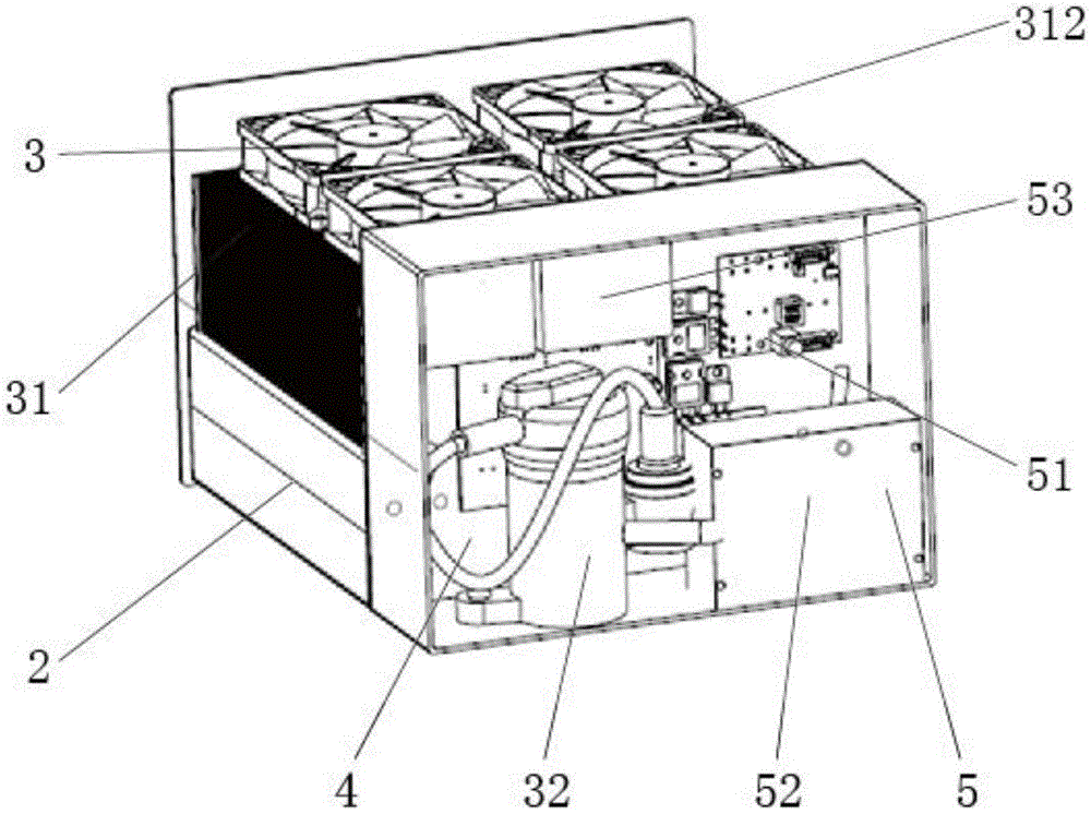
fig. 2 is a schematic diagram of an internal structure of a portable high-power fiber laser according to an embodiment of the present invention;
fig. 3 is a schematic structural diagram of an optical path module of a portable high-power fiber laser disclosed in an embodiment of the present invention;
fig. 4 is a schematic diagram of a pumping optical path structure of a portable high-power fiber laser disclosed in an embodiment of the present invention;
fig. 5 is a schematic diagram of a laser optical path structure of a portable high-power fiber laser disclosed in an embodiment of the present invention;
fig. 6 is a schematic view of an internal structure of a substrate according to an embodiment of the present invention;
fig. 7 is a schematic structural diagram of a condenser according to an embodiment of the present invention;
fig. 8 is a schematic diagram of the operation of the direct refrigeration module according to the embodiment of the present invention.
Reference numerals
1-case, 11-input interface, 12-communication interface, 13-air outlet, 14-air inlet, 2-optical path module, 21-shell, 22-base plate, 221-via hole, 23-pumping optical path, 231-pumping source, 232-pumping beam combiner, 233-single fiber, 24-laser optical path, 241-high reflection grating, 242-ytterbium doped gain fiber, 243-low reflection grating, 244-stripping device, 245-temperature sensor, 246-photoelectric sensor, 247-output fiber port, 3-direct refrigeration module, 31-condenser, 311-fin, 312-high speed fan, 32-compressor, 33-thermal mass fluid micro-channel, 331-photoelectric sensor, 34-thermal mass fluid macro-channel, 341-output port, 4-partition board, 5-circuit module, 51-main control board, 52-refrigeration drive board, 53-power board, 6-throttle valve.
Detailed Description
The following are specific embodiments of the present invention and the accompanying drawings are used to further describe the technical solution of the present invention, but the present invention is not limited to these embodiments.
As shown in fig. 1-8, a portable high-power fiber laser includes a case 1, a light path module 2, a direct refrigeration module 3, and a circuit module 5 connected to each other are disposed in the case 1, the light path module 2 includes a housing 21, a substrate 22 dividing the housing 21 into an upper portion and a lower portion is disposed in the middle of the housing, a cavity is disposed in the middle of the substrate 22, a pumping light path 23 is disposed below the substrate 22, a laser light path 24 is disposed above the substrate 22, the pumping light path 23 includes a pumping source 231 and a pumping combiner 232 fixed on the substrate 22, the laser light path 24 includes a high-reflection grating 241, a ytterbium-doped gain fiber 242, a low-reflection grating 243, a mode stripper 244, and an output fiber port 247, the high-reflection grating 241 is connected to the pumping combiner 232 and the ytterbium-doped gain fiber 242, the low-reflection grating 243 is connected to the ytterbium-doped gain fiber 242 and the mode stripper 244, the stripper 244 is connected to the output fiber port 247;
the direct refrigeration module 3 comprises a condenser 31, a compressor 32, a thermal mass fluid micro-channel 33 and a thermal mass fluid macro-channel 34, the condenser 31 is fixed above the optical path module 2 in the case 1, the compressor 32 is fixed on the side edge of the optical path module 2, a partition plate 4 is arranged between the compressor and the optical path module 2, the thermal mass fluid micro-channel 33 and the thermal mass fluid macro-channel 34 are connected in series and are both arranged in the middle cavity of the substrate 22, and two ends of the thermal mass fluid macro-channel 34 are respectively connected with the condenser 31 and the compressor 32;
the circuit module 5 comprises a main control board 51, a refrigeration drive board 52 and a power board 53, the main control board 51 and the power board 53 are fixed on the partition board 4 near the side of the compressor 32, and the refrigeration drive board 52 is arranged in the case 1 below the main control board 51.
In this embodiment, the working principle of the light path module 2 is as follows: the multiple optical fibers output by the pump source 231 are bundled into a single fiber 233 through a pump beam combiner 232, the single fiber 233 passes through a high reflective grating 241 of a laser oscillator after passing through a through hole 221, and then is absorbed by the ytterbium-doped gain fiber 242 to generate stimulated emission fluorescence with the wavelength of 1060 1080nm, the fluorescence is transmitted and amplified along the ytterbium-doped gain fiber 242 until a low reflective grating 243 forms positive feedback and is continuously enhanced, the fluorescence is finally output from the low reflective grating 243 to a mode stripper 244, the residual pump light in the cladding of the single fiber 233 is stripped, and finally the laser is expanded from an output optical fiber port 247 and then output.
All optical fiber devices of the optical fiber laser require matching of fiber cores and cladding layers so as to reduce welding loss of joints and improve photoelectric efficiency of the laser.
In this embodiment, the working principle of the direct refrigeration module 3 is as follows: the direct refrigeration module 3 is a totally enclosed refrigerant circulation system, the phase-change thermal mass (such as freon, R134a, and other refrigerants) from the throttle valve 6 enters the thermal mass fluid macro-channel 34 in the substrate 22 through the input port 331, absorbs the redundant heat generated by the pump source 231 and the pump beam combiner 232 when passing through the position of the thermal mass fluid micro-channel 33 connected in series with the same, generates phase change, converts the phase change into gas phase through the liquid state, outputs the gas phase into the compressor 32 through the output port 341, the main control board 51 controls the refrigeration driving board 52 to drive the compressor 32 to push the gaseous phase-change thermal mass into the condenser 31, the heat of the phase-change thermal mass is transferred to the fins 311, then completes the heat exchange with the air through the high-speed fan 312, converts the gaseous phase-change thermal mass into gas-liquid mixed thermal mass, the condenser 31 outputs the gas phase change thermal mass to the throttle valve 6, and returns to the thermal mass fluid macro-channel 34 and the thermal mass fluid micro-channel 33 in the, the cooling cycle is completed.
Preferably, the pumping sources 231 are four and arranged on the substrate 22 side by side, and the edge of the substrate 22 is provided with a plurality of through holes 221 penetrating up and down for connecting channels of the pumping optical path 23 and the laser optical path 24.
Preferably, the stripper 244 is provided with a temperature sensor 245 and a photoelectric sensor 246, which are used for monitoring the state of the fiber laser and performing closed-loop control, and the working state of the fiber laser is set according to the instruction requirement.
Preferably, an input port 331 and an output port 341 are provided at a side edge of the substrate 22, the input port 331 is connected to the condenser 31 through a thermal mass copper pipe, and the output port 341 is connected to the compressor 32 through a thermal mass copper pipe.
Preferably, the thermal mass fluid micro-channel 33 is composed of a plurality of parallel copper capillaries, five thermal mass fluid micro-channels 33 are correspondingly arranged below the pumping source 231 and the pumping combiner 232, and the five thermal mass fluid micro-channels 33 are connected in series through the thermal mass fluid macro-channel 34 and are used for absorbing redundant heat of the pumping source 231 and the pumping combiner 232 and cooling the optical fiber laser.
Preferably, the condenser 31 includes fins 311 and high-speed fans 312, and the four fans 312 are arranged on the fins 311 in a rectangular shape, so that the heat dissipation speed is high, and the structure is compact.
Preferably, the top of machine case 1 is equipped with four circular air outlets 13, the side that is close to condenser 31 on machine case 1 is equipped with rectangle air intake 14, two air intake 14 symmetry sets up in the both sides face of machine case 1, realizes condenser 31's quick heat dissipation, air outlet 13 and air intake 14 all are equipped with the dust filter screen, prevent that the dust from entering into fiber laser's machine case 1.
Preferably, the housing 21 is made of a heat insulating material, and the circuit module 5 is connected to an input interface 11 and a communication interface 12 fixed on a side surface of the chassis 1. The input interface 101 is connected to a dc power supply, the input voltage is 20-100V, and the communication interface 12 can communicate with an upper computer outside the case 1.
Preferably, the bonding surfaces of the pumping optical path 23, the laser optical path 24 and the substrate 22 are filled with a heat conducting medium with a low thermal resistance coefficient, and a transparent heat conducting gel is covered on the bonding surfaces, so that heat generated during the operation of the pumping optical path 23 and the laser optical path 24 is absorbed by the phase change thermal mass in the substrate 22.
In this embodiment, the main control board 51 of the fiber laser turns on or off the optical path module 2 and controls the voltage and current of the optical path module after receiving an external input command. The refrigeration drive board 52 controls the opening and the rotating speed of the condenser 31 and the compressor 32, and the refrigeration drive board 52 receives the temperature signal of the temperature sensor 245 and the instruction signal of the main control board 51, performs matching control on the direct refrigeration module 3, and generates the cooling capacity equal to the heat dissipation requirements of the pumping source 231, the pumping combiner 232 and the fiber laser, so as to realize accurate control on the fiber laser.
Finally, it should be noted that: although the present invention has been described in detail with reference to the foregoing embodiments, it will be apparent to those skilled in the art that modifications may be made to the embodiments described in the foregoing embodiments, or equivalents may be substituted for elements thereof. Any modification, equivalent replacement, or improvement made within the spirit and principle of the present invention should be included in the content of the present invention within the protection scope of the present invention.