Individual weighing device of chicken
Technical Field
The utility model relates to a weighing device technical field specifically is an individual weighing device of chicken.
Background
With the development of science and technology, the breeding industry is continuously improved, the chicken farm breeding is continuously improved, the chicken growth observation and breeding needs to be carried out, the devices on the weighing equipment are more and more, and therefore the existing chicken individual weighing device basically meets the requirements of people, but still has some problems.
The first problem is that: traditional individual weighing device of chicken is a whole, and after weighing, weighing device can't carry out simple dismouting and deposit, can only place outside, long-time placing at will, and weighing device can receive the influence of some external forces and receive the damage, when the transportation, also has certain inconvenience.
The second problem is that: traditional individual weighing device of chicken, before using, need pass through the button to weighing device, debug, weigh the chicken after debugging well, but when weighing, touch the button by mistake easily, lead to the inaccurate of weighing result.
Therefore, an individual chicken weighing device is needed to solve the above problems.
SUMMERY OF THE UTILITY MODEL
An object of the utility model is to provide an individual weighing device of chicken is in order to solve the inconvenient problem of dismouting that proposes in the above-mentioned background art.
In order to achieve the above object, the utility model provides a following technical scheme: an individual chicken weighing device comprises a weighing main body, wherein the weighing main body comprises a weighing device, a bearing plate, a shock absorber, a placing cylinder and a button, the bearing plate is arranged on the upper side of the weighing device, a third open slot is formed in the bearing plate, the shock absorber is inserted in the third open slot, the placing cylinder is arranged at the upper end of the shock absorber, a sixth open slot is formed in each shock absorber, a disassembling and assembling mechanism is arranged in each sixth open slot and is convenient to disassemble and assemble, each disassembling and assembling mechanism comprises a bolt rod, a slide rail, a limiting block, a first spring, a second connecting block, a push plate, a rubber block and a protective pad and is convenient to disassemble and assemble, the bolt rods are inserted in the sixth open slots, one ends of the bolt rods, far away from the sixth open slot, are inserted in the fourth open slot, the outer sides of the fourth open slot are all opened in the bearing plate, and one ends of the bolt rods, far away from the shock, one side that the bolt pole was kept away from to first connecting block has all linked firmly the slider, and the one end that first connecting block was kept away from to the slider all slides on the slide rail, one side that the bolt pole was kept away from to the slide rail has all linked firmly on the bearing plate, and one side that the bumper shock absorber was kept away from to the bolt pole has all linked firmly first spring, the one end that the bolt pole was kept away from to first spring has all linked firmly on the bearing plate, and one side that the slide rail was kept away from to the bolt pole has all linked firmly the second connecting block, the one end that the bolt pole was kept away from to the second connecting block is all inserted and is established in the fifth fluting, and the fifth fluting outside all sets up in the bearing plate, one side that the bolt.
Preferably, the front of the weighing device is provided with a button, the interior of the weighing device is provided with a protective device for facilitating protection, the protective device comprises a rotating rod, a protective glass plate, a third connecting block, a fourth connecting block, a second spring and a pull handle, the protective device is convenient to protect, the upper end of the weighing device is connected with the rotating rod in a switching manner, one end of the rotating rod, far away from the weighing device, is connected with the protective glass plate in a switching manner, one end of the protective glass plate, far away from the rotating rod, is fixedly connected with the third connecting block, one end of the third connecting block, far away from the protective glass plate, is inserted into the first open groove, the outer side of the first open groove is inserted into the weighing device, the third connecting block is internally provided with a seventh open groove, a fourth connecting block is inserted into the seventh open groove, one side of the fourth connecting block, far away from the weighing device, is fixedly connected with the second spring, one end of the second spring, far away from the fourth connecting block, and the outer side of the second slot is arranged in the weighing device.
Preferably, one side that the second connecting block was kept away from to the push pedal has all linked firmly the block rubber, is convenient for promote, and the block rubber sets up to "ladder" shape, is convenient for promote.
Preferably, the inside protection pad that all is provided with of fifth fluting is convenient for protect, and the protection pad keeps away from one side of second connecting block and all links firmly on the bearing plate, is convenient for protect.
Preferably, one side of the fourth connecting block, which is far away from the weighing device, is fixedly connected with a buffer block, so that buffering is facilitated, and the buffer block is arranged in an I shape, so that buffering is facilitated.
Preferably, one side of the protective glass plate, which is far away from the third connecting block, is fixedly connected with a pull handle, so that the protective glass plate is convenient to pull, and the pull handle is U-shaped, so that the protective glass plate is convenient to pull.
Compared with the prior art, the beneficial effects of the utility model are that:
1. the chicken individual weighing device is provided with a bolt rod, a slide rail, a limiting block, a first spring, a second connecting block, a push plate, rubber blocks and a protective pad, wherein before weighing, a shock absorber is inserted into a third groove and pressed downwards, the shock absorber extrudes the bolt rods on two sides, so that the bolt rods compress the first spring under the assistance of the sliding of the first connecting block and the slide block, when the bolt rods reach the position of a sixth groove, the bolt rods are driven to be inserted into the sixth groove due to the elastic potential energy of the first spring, the shock absorber and the bearing plate are installed and fixed, when weighing and dismantling are carried out, the rubber blocks on two sides are pushed to drive the second connecting block and the bolt rods, under the assistance of the sliding of the first connecting block and the slide block, the first spring is compressed, the bolt rods are pulled out of the sixth groove, the shock absorber is pulled, the shock absorber and the bearing plate are released from a clamping state, the rubber blocks are loosened, under the elastic potential energy of the first spring, the original working state is recovered, the problem that the traditional chicken individual weighing device is a whole, after weighing, the weighing device cannot be simply disassembled, assembled and stored, can only be placed outside, can be randomly placed for a long time, and can be damaged under the influence of some external force, and certain inconvenience is caused during transportation is solved, so that the weighing device can be disassembled and stored after weighing, the service life of the weighing device is prolonged, the transportation is more convenient during transportation, the damage is reduced, and the later maintenance is reduced;
2. the chicken individual weighing device is provided with a rotating rod, a protective glass plate, a third connecting block, a fourth connecting block, a second spring and a pull handle, wherein before weighing, the pull handle is pulled to enable the fourth connecting block to be extruded and slide into a seventh groove, the second spring is compressed, after the fourth connecting block is inserted into the seventh groove, under the limit rotation of the rotating rod, the protective glass plate is opened, after a button is arranged, the protective glass plate is pulled and pressed to enable the third connecting block to be inserted into the first groove, the fourth connecting block is extruded into the seventh groove, when the position of the second groove is reached, the fourth connecting block drives the fourth connecting block to be inserted into the second groove under the elastic potential energy of the second spring, the traditional chicken individual weighing device is solved, before using, the weighing device needs to be debugged through the button, the chicken is weighed after debugging, but when weighing is carried out, the button is touched to the mistake easily, leads to the unsafe problem of weighing result, makes after setting up good data, during weighing, avoids causing the mistake to touch because of external force to the button, promotes the accuracy of weighing, is convenient for weigh, improves work efficiency.
Drawings
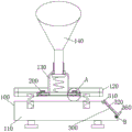
FIG. 1 is a schematic front view of the structure of the present invention;
FIG. 2 is a schematic sectional view of the right side of the structure of the present invention;
fig. 3 is a schematic structural view of a portion a in fig. 2 according to the present invention;
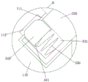
fig. 4 is a schematic structural diagram of the position B in fig. 2 according to the present invention.
In the figure: 100. weighing the main body; 110. a weighing device; 111. a first slot; 112. a second slot; 120. a bearing plate; 121. a third slot is formed; 122. a fourth slot is formed; 123. fifthly, slotting; 130. a shock absorber; 131. a sixth groove is formed; 140. placing the cylinder; 150. a button; 200. a disassembly and assembly mechanism; 210. a latch rod; 211. a first connection block; 212. a slider; 220. a slide rail; 230. a limiting block; 240. a first spring; 250. a second connecting block; 260. pushing the plate; 270. a rubber block; 280. a protective pad; 300. a guard; 310. a rotating rod; 320. a cover glass plate; 330. a third connecting block; 331. a seventh slot; 340. a fourth connecting block; 341. a buffer block; 350. a second spring; 360. and (5) pulling the handle.
Detailed Description
The technical solutions in the embodiments of the present invention will be described clearly and completely with reference to the accompanying drawings in the embodiments of the present invention, and it is obvious that the described embodiments are only some embodiments of the present invention, not all embodiments. Based on the embodiments in the present invention, all other embodiments obtained by a person skilled in the art without creative work belong to the protection scope of the present invention.
Referring to fig. 1-4, the present invention provides an embodiment: an individual chicken weighing device comprises a weighing main body 100, wherein the weighing main body 100 comprises a weighing device 110, a bearing plate 120, a shock absorber 130, a placing cylinder 140 and a button 150, the bearing plate 120 is arranged on the upper side of the weighing device 110, a third groove 121 is formed in the bearing plate 120, the shock absorber 130 is inserted in the third groove 121, the placing cylinder 140 is arranged at the upper end of the shock absorber 130, a sixth groove 131 is formed in each shock absorber 130, a dismounting mechanism 200 convenient to dismount and mount is arranged in each sixth groove 131 and convenient to connect, the dismounting mechanism 200 comprises a bolt rod 210 convenient to dismount and mount, a slide rail 220, a limiting block 230, a first spring 240, a second connecting block 250, a push plate 260, a rubber block 270 and a protective pad 280 and convenient to connect, the bolt rod 210 is inserted in each sixth groove 131, one end, far away from the sixth groove 131, of the bolt rod 210 is inserted in the fourth groove 122, the outer side of the fourth groove 122 is arranged in the bearing plate 120, and the one end that the shock absorber 130 was kept away from to bolt pole 210 all has linked firmly first connecting block 211, the one side that the bolt pole 210 was kept away from to first connecting block 211 all has linked firmly the slider 212, and the one end that the first connecting block 211 was kept away from to slider 212 all slides on slide rail 220, the one side that the bolt pole 210 was kept away from to slide rail 220 all has linked firmly on bearing plate 120, and the one side that the shock absorber 130 was kept away from to bolt pole 210 all has linked firmly first spring 240, the one end that the bolt pole 210 was kept away from to first spring 240 all has linked firmly on bearing plate 120, and the one side that the slide rail 220 was kept away from to bolt pole 210 all has linked firmly second connecting block 250, the one end that the bolt pole 210 was kept away from to second connecting block 250 all is inserted and is established in fifth fluting 123, and the fifth fluting 123 outside all is seted up in bearing plate 120, the one.
The front surface of the weighing device 110 is provided with a button 150, the interior of the weighing device 110 is provided with a protection device 300 which is convenient to protect and is convenient to connect, the protection device 300 comprises a rotating rod 310 which is convenient to protect, a protective glass plate 320, a third connecting block 330, a fourth connecting block 340, a second spring 350 and a pull handle 360 which are convenient to connect, the upper end of the weighing device 110 is connected with the rotating rod 310 in a rotating way, one end of the rotating rod 310, far away from the weighing device 110, is connected with the protective glass plate 320 in a rotating way, one end of the protective glass plate 320, far away from the rotating rod 310, is fixedly connected with the third connecting block 330, one end of the third connecting block 330, far away from the protective glass plate 320, is inserted into the first groove 111, the outer side of the first groove 111 is opened into the weighing device 110, a seventh groove 331 is opened into the third connecting block 330, a fourth connecting block 340 is inserted into the seventh groove 331, one side of the fourth connecting block 340, far away from the weighing device 110, is fixedly connected with the, one end of the fourth connecting block 340 far away from the second spring 350 is inserted into the second slot 112, and the outside of the second slot 112 is opened in the weighing device 110.
One side of the push plate 260 away from the second connecting block 250 is fixedly connected with a rubber block 270 convenient to push, so that the rubber block 270 is convenient to bear the force, and the rubber block 270 is arranged into a ladder shape convenient to push, so that the force is convenient to bear.
The protection pad 280 convenient for protection is arranged in the fifth slot 123 for connection, and one side of the protection pad 280 far away from the second connecting block 250 is fixedly connected to the bearing plate 120 convenient for protection for connection.
One side of the fourth connecting block 340, which is far away from the weighing device 110, is fixedly connected with a buffer block 341 convenient for buffering, and the buffer block 341 is arranged in an "I" shape convenient for buffering and is convenient for connection.
One side of the protection glass plate 320 far from the third connecting block 330 is fixedly connected with a pulling handle 360 convenient to pull, so that the protection glass plate is convenient to bear force, and the pulling handle 360 is in a U shape convenient to pull, so that the protection glass plate is convenient to bear force.
The working principle is as follows: before weighing, the shock absorber 130 is inserted into the third slot 121 and pressed downwards, the shock absorber 130 presses the latch rods 210 on both sides, so that the latch rods 210 are driven to be inserted into the sixth slot 131 by the aid of sliding of the first connecting block 211 and the slider 212 to compress the first spring 240, when the latch rods 210 reach the position of the sixth slot 131, the latch rods 210 are driven to be inserted into the sixth slot 131 due to elastic potential energy of the first spring 240, the shock absorber 130 and the bearing plate 120 are installed and fixed, when weighing is removed, the rubber blocks 270 on both sides are pushed to drive the second connecting block 250 and the latch rods 210, under the aid of sliding of the first connecting block 211 and the slider 212, the first spring 240 is compressed, so that the latch rods 210 are pulled out of the sixth slot 131, the shock absorber 130 is pulled, the shock absorber 130 is disengaged from the bearing plate 120, the rubber blocks 270 are released, and the original working state is restored under the elastic potential energy of the first spring 240.
Before weighing, the pull handle 360 is pulled to enable the fourth connecting block 340 to be extruded and slide into the seventh open groove 331, the second spring 350 is compressed, after the fourth connecting block 340 is inserted into the seventh open groove 331, the protective glass plate 320 is opened under the limiting rotation of the rotating rod 310, after the button 150 is set, the protective glass plate 320 is pulled and pressed to enable the third connecting block 330 to be inserted into the first open groove 111, the fourth connecting block 340 is extruded into the seventh open groove 331, and when the position of the second open groove 112 is reached, the fourth connecting block 340 drives the fourth connecting block 340 to be inserted into the second open groove 112 under the elastic potential energy of the second spring 350.
It is obvious to a person skilled in the art that the invention is not restricted to details of the above-described exemplary embodiments, but that it can be implemented in other specific forms without departing from the spirit or essential characteristics of the invention. The present embodiments are therefore to be considered in all respects as illustrative and not restrictive, the scope of the invention being indicated by the appended claims rather than by the foregoing description, and all changes which come within the meaning and range of equivalency of the claims are therefore intended to be embraced therein. Any reference sign in a claim should not be construed as limiting the claim concerned.