CN213018646U - Lifting structure for security monitoring vertical rod support - Google Patents
Lifting structure for security monitoring vertical rod support Download PDFInfo
- Publication number
- CN213018646U CN213018646U CN202021359605.7U CN202021359605U CN213018646U CN 213018646 U CN213018646 U CN 213018646U CN 202021359605 U CN202021359605 U CN 202021359605U CN 213018646 U CN213018646 U CN 213018646U
- Authority
- CN
- China
- Prior art keywords
- rod
- fixedly connected
- bottom plate
- base
- threaded
- Prior art date
- Legal status (The legal status is an assumption and is not a legal conclusion. Google has not performed a legal analysis and makes no representation as to the accuracy of the status listed.)
- Active
Links
- 238000012544 monitoring process Methods 0.000 title claims abstract description 25
- 229910000831 Steel Inorganic materials 0.000 claims description 12
- 239000010959 steel Substances 0.000 claims description 12
- 230000005540 biological transmission Effects 0.000 claims description 7
- 210000003128 head Anatomy 0.000 description 2
- 238000009434 installation Methods 0.000 description 2
- 238000012423 maintenance Methods 0.000 description 2
- 230000009286 beneficial effect Effects 0.000 description 1
- 238000012986 modification Methods 0.000 description 1
- 230000004048 modification Effects 0.000 description 1
Images

Landscapes
- Burglar Alarm Systems (AREA)
Abstract
The utility model discloses a lifting structure for a security monitoring vertical rod support, which comprises a base, wherein the upper end of the base is contacted with a bottom plate, one end of the bottom plate is rotationally connected with the base through a hinge, one side of the upper end of the bottom plate is rotationally connected with a threaded rod, the surface of the threaded rod is in threaded connection with a threaded sleeve, the surface of the threaded sleeve is fixedly connected with a movable rod, one side of the surface of the movable rod is provided with a rectangular groove, and the upper end of the threaded rod is fixedly connected with a limiting rod. The monitoring camera is convenient to overhaul or replace.
Description
Technical Field
The utility model relates to an elevation structure field especially relates to a be used for security protection control pole setting support elevation structure.
Background
The security monitoring can reflect the monitored object in real time, vividly and truly, not only greatly prolongs the observation distance of human eyes, but also expands the functions of the human eyes, can replace manpower to carry out long-time monitoring in severe environment, enables people to see all the actual conditions of the monitored site, and records the actual conditions through a video recorder. Meanwhile, the alarm system device alarms illegal intrusion, generated alarm signals are input into the alarm host, and the alarm host triggers the monitoring system to record and record videos.
Security protection control pole setting support elevation structure who uses in the existing market is because simple structure, and the operation is stable easily damaged inadequately, and is more troublesome moreover in installation and later stage maintenance during operation, needs to improve.
SUMMERY OF THE UTILITY MODEL
The utility model aims at solving the shortcoming that exists among the prior art, and the utility model provides a be used for security protection control pole setting support elevation structure.
In order to achieve the above purpose, the utility model adopts the following technical scheme: a lifting structure for a security monitoring vertical rod support comprises a base, wherein the upper end of the base is contacted with a bottom plate, one end of the bottom plate is rotatably connected with the base through a hinge, one side of the upper end of the bottom plate is rotatably connected with a threaded rod, the surface of the threaded rod is in threaded connection with a threaded sleeve, the surface of the threaded sleeve is fixedly connected with a movable rod, one side of the surface of the movable rod is provided with a rectangular groove, the upper end of the threaded rod is fixedly connected with a limiting rod, the upper end of the movable rod is fixedly connected with a fixed rod, the bottom of one end of the fixed rod is fixedly connected with a monitoring camera, one side of the upper end of the bottom plate is fixedly connected with a motor, the output end of the motor is fixedly connected with a driving shaft, the surface of the driving shaft is fixedly connected with a first, the motor base is characterized in that one end, close to the motor, of the base plate is provided with a first threaded hole, the surface, located below the first threaded hole, of the base is provided with a second threaded hole, the inner threads of the first threaded hole and the second threaded hole are connected with screws, and one end, close to the motor, of the base plate is fixedly connected with a steel wire.
As a further description of the above technical solution:
the limiting rod penetrates through the rectangular groove to be in smooth contact with the rectangular groove.
As a further description of the above technical solution:
the first belt pulley and the second belt pulley are in transmission connection through a belt.
As a further description of the above technical solution:
the other end of the steel wire is fixedly connected with the surface of the base.
As a further description of the above technical solution:
when the steel wire is completely extended, the threaded rod keeps a certain distance from the ground.
As a further description of the above technical solution:
the motor is electrically connected to a power source and a switch.
As a further description of the above technical solution:
the base is fixedly installed with the ground.
The utility model discloses following beneficial effect has:
the utility model discloses a set up threaded rod, thread bush, movable rod, rectangular channel, gag lever post, motor, first belt pulley, second belt pulley and belt isotructure component, can ensure the stable lift of movable rod, improved the device's security.
The utility model discloses a set up structural component such as base, bottom plate, first screw hole, second screw hole, screw and steel wire, when needs installation or maintenance change surveillance camera head, unscrew the screw and can make threaded rod and movable rod rotate and form fixed contained angle to ground, conveniently overhaul or change surveillance camera head.
Drawings
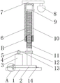
Fig. 1 is a side view of a lifting structure for a security monitoring upright support provided by the present invention;
fig. 2 is a schematic view of a movable rod for a lifting structure of a security monitoring vertical rod support provided by the present invention;
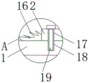
FIG. 3 is an enlarged view taken at A in FIG. 1;
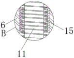
fig. 4 is an enlarged view at B in fig. 1.
Illustration of the drawings:
1. a base; 2. a base plate; 3. an electric motor; 4. a first pulley; 5. a drive shaft; 6. a movable rod; 7. fixing the rod; 8. a surveillance camera; 9. a limiting rod; 10. a rectangular groove; 11. a threaded rod; 12. a second pulley; 13. a belt; 14. a hinge; 15. a threaded sleeve; 16. a steel wire; 17. a first threaded hole; 18. a second threaded hole; 19. and (4) screws.
Detailed Description
The technical solutions in the embodiments of the present invention will be described clearly and completely with reference to the accompanying drawings in the embodiments of the present invention, and it is obvious that the described embodiments are only some embodiments of the present invention, not all embodiments. Based on the embodiments in the present invention, all other embodiments obtained by a person skilled in the art without creative work belong to the protection scope of the present invention.
In the description of the present invention, it should be noted that the terms "center", "upper", "lower", "left", "right", "vertical", "horizontal", "inner", "outer", and the like indicate orientations or positional relationships based on the orientations or positional relationships shown in the drawings, and are only for convenience of description and simplification of description, but do not indicate or imply that the device or element referred to must have a specific orientation, be constructed and operated in a specific orientation, and thus, should not be construed as limiting the present invention; the terms "first," "second," and "third" are used for descriptive purposes only and are not to be construed as indicating or implying relative importance, and furthermore, unless otherwise explicitly stated or limited, the terms "mounted," "connected," and "connected" are to be construed broadly and may be, for example, fixedly connected, detachably connected, or integrally connected; can be mechanically or electrically connected; they may be connected directly or indirectly through intervening media, or they may be interconnected between two elements. The specific meaning of the above terms in the present invention can be understood in specific cases to those skilled in the art.
Referring to fig. 1-4, the present invention provides an embodiment: a lifting structure for a security monitoring upright pole support comprises a base 1, the upper end of the base 1 is contacted with a bottom plate 2, one end of the bottom plate 2 is rotatably connected with the base 1 through a hinge 14, one side of the upper end of the bottom plate 2 is rotatably connected with a threaded rod 11, the surface of the threaded rod 11 is in threaded connection with a threaded sleeve 15, up-and-down movement of a movable rod 6 is realized, the surface of the threaded sleeve 15 is fixedly connected with a movable rod 6, one side of the surface of the movable rod 6 is provided with a rectangular groove 10, the upper end of the threaded rod 11 is fixedly connected with a limiting rod 9, the movement direction of the movable rod 6 is limited, the movable rod is enabled to do up-and-down linear movement, the upper end of the movable rod 6 is fixedly connected with a fixed rod 7, the bottom of one end of the fixed rod 7 is fixedly connected with a monitoring camera 8, one, transmission power, the first belt pulley 4 of fixed surface of drive shaft 5, transmission power, the position fixedly connected with second belt pulley 12 that the bottom of threaded rod 11 is close to first belt pulley 4, transmission power, first screw hole 17 has been seted up to the one end that bottom plate 2 is close to motor 3, second screw hole 18 has been seted up to the below surface that base 1 is located first screw hole 17, the internal thread of first screw hole 17 and second screw hole 18 is connected with screw 19, the fixed of bottom plate 2 is realized to first screw hole 17 of cooperation and second screw hole 18, bottom plate 2 is close to motor 3's one end fixedly connected with steel wire 16.
The limiting rod 9 penetrates through the rectangular groove 10 to be in smooth contact with the rectangular groove, and the moving direction of the movable rod 6 is limited to prevent the movable rod from rotating. The first belt pulley 4 and the second belt pulley 12 are in transmission connection through a belt 13 to transmit power. The other end of the steel wire 16 is fixedly connected with the surface of the base 1. When the steel wire 16 extends completely, the threaded rod 11 keeps a certain distance from the ground, and the situation that the monitoring camera 8 rotates to the ground due to the fact that the rotating angle of the bottom plate 2 is too large is avoided. The motor 3 is electrically connected with a power supply and a switch to realize the control of the device. The base 1 is fixedly installed with the ground, and the positions of the base 1 and the bottom plate 2 are fixed.
The working principle is as follows: when the monitoring camera 8 needs to be installed or overhauled, firstly, the screw 19 is screwed out of the first threaded hole 17 and the second threaded hole 18, then the threaded rod 11 and the bottom plate 2 are rotated towards one side close to the monitoring camera 8 until the steel wire 16 is straightened, the threaded rod 11 and the movable rod 6 form a fixed included angle with the ground, thereby the monitoring camera 8 is conveniently overhauled or replaced, after the overhaul or the replacement is finished, the bottom plate 2 is rotated back to the original position, then the screw 19 is screwed into the first threaded hole 17 and the second threaded hole 18, the device can be fixed, when the height is required to be adjusted, the driving motor 3 drives the threaded rod 11 to rotate through the transmission of the first belt pulley 4, the second belt pulley 12 and the belt 13, then the threaded sleeve 15 moves up and down, the movable rod 6 is driven to move up and down, and the realization of the monitoring camera 8 is moved.
Finally, it should be noted that: although the present invention has been described in detail with reference to the foregoing embodiments, it will be apparent to those skilled in the art that modifications and variations can be made in the embodiments or in part of the technical features of the embodiments without departing from the spirit and the scope of the invention.
Claims (7)
1. The utility model provides a be used for security protection control pole setting support elevation structure, includes base (1), its characterized in that: the upper end of the base (1) is contacted with a bottom plate (2), one end of the bottom plate (2) is rotatably connected with the base (1) through a hinge (14), one side of the upper end of the bottom plate (2) is rotatably connected with a threaded rod (11), the surface of the threaded rod (11) is in threaded connection with a threaded sleeve (15), the surface of the threaded sleeve (15) is fixedly connected with a movable rod (6), one side of the surface of the movable rod (6) is provided with a rectangular groove (10), the upper end of the threaded rod (11) is fixedly connected with a limiting rod (9), the upper end of the movable rod (6) is fixedly connected with a fixed rod (7), the bottom of one end of the fixed rod (7) is fixedly connected with a monitoring camera (8), one side of the upper end of the bottom plate (2) is fixedly connected with a motor (3), and the output end of the motor, the utility model discloses a motor, including drive shaft (5), the fixed surface of drive shaft (5) is connected with first belt pulley (4), the position fixedly connected with second belt pulley (12) that the bottom of threaded rod (11) is close to first belt pulley (4), bottom plate (2) are close to the one end of motor (3) and have seted up first screw hole (17), second screw hole (18) have been seted up to base (1) below surface that is located first screw hole (17), the internal thread of first screw hole (17) and second screw hole (18) is connected with screw (19), bottom plate (2) are close to one end fixedly connected with steel wire (16) of motor (3).
2. The lifting structure for the security monitoring upright rod bracket according to claim 1, characterized in that: the limiting rod (9) penetrates through the rectangular groove (10) to be in smooth contact with the rectangular groove.
3. The lifting structure for the security monitoring upright rod bracket according to claim 1, characterized in that: the first belt pulley (4) is in transmission connection with the second belt pulley (12) through a belt (13).
4. The lifting structure for the security monitoring upright rod bracket according to claim 1, characterized in that: the other end of the steel wire (16) is fixedly connected with the surface of the base (1).
5. The lifting structure for the security monitoring upright rod bracket according to claim 1, characterized in that: when the steel wire (16) is fully extended, the threaded rod (11) keeps a certain distance from the ground.
6. The lifting structure for the security monitoring upright rod bracket according to claim 1, characterized in that: the motor (3) is electrically connected with a power supply and a switch.
7. The lifting structure for the security monitoring upright rod bracket according to claim 1, characterized in that: the base (1) is fixedly installed with the ground.
Priority Applications (1)
| Application Number | Priority Date | Filing Date | Title |
|---|---|---|---|
| CN202021359605.7U CN213018646U (en) | 2020-07-13 | 2020-07-13 | Lifting structure for security monitoring vertical rod support |
Applications Claiming Priority (1)
| Application Number | Priority Date | Filing Date | Title |
|---|---|---|---|
| CN202021359605.7U CN213018646U (en) | 2020-07-13 | 2020-07-13 | Lifting structure for security monitoring vertical rod support |
Publications (1)
| Publication Number | Publication Date |
|---|---|
| CN213018646U true CN213018646U (en) | 2021-04-20 |
Family
ID=75501887
Family Applications (1)
| Application Number | Title | Priority Date | Filing Date |
|---|---|---|---|
| CN202021359605.7U Active CN213018646U (en) | 2020-07-13 | 2020-07-13 | Lifting structure for security monitoring vertical rod support |
Country Status (1)
| Country | Link |
|---|---|
| CN (1) | CN213018646U (en) |
Cited By (1)
| Publication number | Priority date | Publication date | Assignee | Title |
|---|---|---|---|---|
| CN114639226A (en) * | 2022-03-17 | 2022-06-17 | 国网辽宁省电力有限公司信息通信分公司 | Three-dimensional computer lab equipment information acquisition system with electric leakage alarming function |
-
2020
- 2020-07-13 CN CN202021359605.7U patent/CN213018646U/en active Active
Cited By (1)
| Publication number | Priority date | Publication date | Assignee | Title |
|---|---|---|---|---|
| CN114639226A (en) * | 2022-03-17 | 2022-06-17 | 国网辽宁省电力有限公司信息通信分公司 | Three-dimensional computer lab equipment information acquisition system with electric leakage alarming function |
Similar Documents
| Publication | Publication Date | Title |
|---|---|---|
| CN112422913B (en) | Self-cleaning monitoring camera convenient to adjust | |
| CN214675283U (en) | Security monitoring camera with dustproof ability | |
| CN104767967B (en) | A kind of removable comprehensively monitoring alarm system of the LAN based on LabVIEW | |
| CN209762618U (en) | Camera for security protection monitored control system convenient to installation | |
| CN212776388U (en) | Wisdom mill flow management equipment | |
| CN117081235A (en) | A monitoring system for new energy power generation | |
| CN216280241U (en) | Be used for building engineering remote monitering equipment | |
| CN216438392U (en) | A small animal invasion automatic expulsion and remote inspection device for power distribution equipment | |
| CN109185646B (en) | Urban road traffic monitor detection method | |
| CN220038051U (en) | All-angle rotation security monitoring device | |
| CN219809701U (en) | Building networking monitoring mechanism | |
| CN216243067U (en) | Adjustable lifting device for security alarm monitoring equipment | |
| CN220135020U (en) | Video monitoring recheck emergency alarm equipment | |
| CN213394442U (en) | Intelligent supervision system for electric power construction site | |
| CN213361805U (en) | Monitoring equipment mounting structure for network security | |
| CN210297910U (en) | Security protection supervisory equipment | |
| CN113963508B (en) | Electric shock prevention alarm device for pole and tower operating personnel | |
| CN221375286U (en) | Security protection is with adjustable video monitoring device | |
| CN221784244U (en) | An intelligent building indoor monitoring device | |
| CN221858240U (en) | Adjustable base of monitoring equipment | |
| CN220817135U (en) | Security monitoring equipment | |
| CN221222073U (en) | Security protection control support | |
| CN221504635U (en) | Monitoring equipment | |
| CN221407675U (en) | Cable short-circuit grounding wire clamp | |
| CN214500553U (en) | Road bridge engineering machine tool remote monitoring support |
Legal Events
| Date | Code | Title | Description |
|---|---|---|---|
| GR01 | Patent grant | ||
| GR01 | Patent grant |