CN213010613U - Feeding device - Google Patents
Feeding device Download PDFInfo
- Publication number
- CN213010613U CN213010613U CN202021717417.7U CN202021717417U CN213010613U CN 213010613 U CN213010613 U CN 213010613U CN 202021717417 U CN202021717417 U CN 202021717417U CN 213010613 U CN213010613 U CN 213010613U
- Authority
- CN
- China
- Prior art keywords
- mounting plate
- limiting block
- station
- fixedly connected
- close
- Prior art date
- Legal status (The legal status is an assumption and is not a legal conclusion. Google has not performed a legal analysis and makes no representation as to the accuracy of the status listed.)
- Active
Links
Images


Abstract
The utility model discloses a feeding device, which comprises a frame; the feeding station and the carrying station are respectively positioned in the outer side areas of two side ends of the rack, the feeding station is used for loading workpieces on the feeding disc assembly, and the carrying station is used for transferring the workpieces in the feeding disc assembly to a set station; and at least two groups of the charging tray assemblies are arranged in the rack at intervals along the vertical direction. This loading attachment can improve this loading attachment's loading capacity under the unchangeable operating mode of occupation space.
Description
Technical Field
The utility model relates to a lithium cell manufacturing equips technical field, especially relates to a loading attachment.
Background
In the lithium battery module manufacturing process, need assemble the part in this lithium battery module, this part needs shift to the transport station by the material loading station to conveniently snatch this part to the lithium battery module in.
The existing feeding device has small loading capacity and can reduce the production efficiency of the lithium battery module.
SUMMERY OF THE UTILITY MODEL
The application provides a loading attachment, and the device can improve this loading attachment's loading capacity under the unchangeable operating mode of occupation space.
The application provides a loading attachment includes: a frame; the feeding station and the carrying station are respectively positioned in the outer side areas of two side ends of the rack, the feeding station is used for loading workpieces on the feeding disc assembly, and the carrying station is used for transferring the workpieces in the feeding disc assembly to a set station; and at least two groups of the charging tray assemblies are arranged in the rack at intervals along the vertical direction.
Further, the tray assembly includes: the first mounting plate is arranged in the rack; the second mounting plate is horizontally and slidably connected to the upper surface of the first mounting plate; the third mounting plate is horizontally and slidably connected to the upper surface of the second mounting plate; wherein the third mounting plate is movable completely to an outer region of the frame to move the third mounting plate to the loading station.
Further, a first sliding block is fixedly arranged on the upper surface of the side end, close to the feeding station, of the first mounting plate; and a first line rail is fixedly arranged on the lower surface of the second mounting plate and is in sliding connection with the first sliding block.
Further, a second sliding block is fixedly arranged on the upper surface of the side end, close to the feeding station, of the second mounting plate; and a second line rail is fixedly arranged on the lower surface of the third mounting plate and is in sliding connection with the second sliding block.
Furthermore, a plurality of grooves are formed in the upper surface of the third mounting plate, and the grooves are used for placing the workpieces.
Furthermore, the tray assembly also comprises a support which is fixedly connected in the rack, and the first mounting plate is horizontally connected to the support in a sliding manner; and a driving piece is fixedly arranged on the support and used for driving the first mounting plate to move towards the conveying station so as to enable the third mounting plate to move to the conveying station.
Further, a first limiting block is fixedly connected to the upper surface of the side end, close to the feeding station, of the first mounting plate, a second limiting block is fixedly connected to the side end, close to the carrying station, of the second mounting plate, and the first limiting block and the second limiting block are arranged oppositely; a third limiting block is fixedly connected to the upper surface of the side end, close to the carrying station, of the first mounting plate, and the third limiting block and the second limiting block are arranged oppositely; the second limiting block is located between the third limiting block and the first limiting block, and the first limiting block and the third limiting block are used for limiting the horizontal movement stroke of the second mounting plate on the first mounting plate.
Further, a fourth limiting block is fixedly connected to the upper surface of the side end, close to the feeding station, of the second mounting plate, a fifth limiting block is fixedly connected to the side end, far away from the feeding station, of the third mounting plate, and the fourth limiting block and the fifth limiting block are arranged oppositely; a second limiting block is fixedly connected to the surface of the side end, close to the carrying station, of the second mounting plate, and the fourth limiting block is arranged opposite to the second limiting block; the fourth limiting block is located between the second limiting block and the fourth limiting block, and the second limiting block and the fourth limiting block are used for limiting the moving stroke of the second mounting plate.
Further, a clamping block is fixedly arranged on the first mounting plate, and an elastic plunger is fixedly arranged on the third mounting plate; the elastic plunger can be clamped into the clamping block and is used for fixedly connecting the first mounting plate, the second mounting plate and the third mounting plate relatively.
Furthermore, the two groups of supports are arranged at intervals and are fixedly connected to the rack respectively, and third linear rails are fixedly connected to the side ends of the two groups of supports; the first mounting plate sets up in two sets of between the support, and be in first mounting plate both sides end all links firmly the third slider, the third slider set up in first mounting plate is close to the side of material loading station, the third slider with third track sliding connection.
The beneficial effect of this application is:
(1) the loading capacity of the feeding device can be improved under the working condition that the occupied space is not changed.
(2) The charging tray subassembly in this frame can set up the multiunit, but independent action between the multiunit charging tray subassembly, and multiunit charging tray subassembly does not have the influence each other, improves this loading attachment's material loading efficiency.
Drawings
In order to more clearly illustrate the technical solutions in the embodiments of the present invention, the drawings needed to be used in the embodiments will be briefly described below, and it is obvious that the drawings in the following description are only some embodiments of the present invention, and it is obvious for those skilled in the art that other drawings can be obtained according to these drawings without creative efforts.
FIG. 1 is a schematic structural diagram of a loading device according to an embodiment of the present application;
FIG. 2 is a schematic view of the tray assembly of FIG. 1;
FIG. 3 is a schematic top view of FIG. 2;
FIG. 4 is a schematic left side view of the structure of FIG. 2;
FIG. 5 is a schematic bottom view of FIG. 2;
FIG. 6 is a schematic view of another configuration of the tray assembly of FIG. 1;
Detailed Description
The technical solutions in the embodiments of the present invention will be described clearly and completely with reference to the accompanying drawings in the embodiments of the present invention, and it is obvious that the described embodiments are only some embodiments of the present invention, not all embodiments. Based on the embodiments of the present invention, all other embodiments obtained by a person of ordinary skill in the art without any creative work belong to the protection scope of the present invention.
Referring to fig. 1 to 6, the feeding device includes a frame 10 and tray assemblies 20, at least two sets of tray assemblies 20 are installed in the frame 10 at intervals along a vertical direction, wherein each set of tray assemblies 20 is connected to the frame 10 in a sliding manner along a horizontal direction, the tray assemblies 20 can move to a feeding station 30 and a carrying station 40 under the action of an external force, and the feeding station 30 and the carrying station 40 are respectively located at outer regions of two side ends of the frame 10.
In this embodiment, the loading station 30 and the carrying station 40 are both located outside the rack 10, when the tray assembly 20 moves to the loading station 30, it is convenient for loading the workpiece on the tray assembly 20, it should be noted that the workpiece may be a copper bar or the like, the workpiece may be loaded in the tray assembly 20 in a manual carrying manner or a manipulator carrying manner, after the tray assembly 20 is filled with the workpiece, the tray assembly 20 may be transferred to the carrying station 40 from the loading station 30, at the carrying station 40, the workpiece on the tray assembly 20 is transferred to a set station, and the set station may be a lithium battery module mounting assembly station.
Because a plurality of sets of tray assemblies 20 are arranged in the rack 10, the plurality of sets of tray assemblies 20 are arranged in a stacked manner at intervals in the vertical direction, so that under the condition that the occupied space of the rack in the horizontal direction is unchanged, the loading device can load more workpieces, and each tray assembly 20 can be independently moved to the loading station 30 and the carrying station 40, so that the movement of each layer of tray assemblies 20 has no influence on each other, for example, when one tray assembly 20 is moved to the carrying station 40, the other tray assembly 20 can be simultaneously moved to the loading station 30, and the loading efficiency of the loading device is improved.
The tray assembly 20 includes a first mounting plate 21, a second mounting plate 22 and a third mounting plate 23, the first mounting plate 21 is disposed on the rack 10, the second mounting plate 22 is horizontally slidably connected to the first mounting plate 21, and the third mounting plate 23 is horizontally slidably connected to the second mounting plate 22.
In order to facilitate manual grabbing of the third mounting plate 23, a handle is fixedly arranged on the third mounting plate 23, and when the handle on the third mounting plate 23 is pulled manually, the third mounting plate 23 and the second mounting plate 22 can both move towards the feeding station 30, so that the third mounting plate 23 moves to the outer side of the rack 10 and the third mounting plate 23 is located at the feeding station 30, and a workpiece can be conveniently fed to the third mounting plate 23 manually.
When the third mounting plate 23 is filled with the workpiece, the third mounting plate 23 can be manually pushed into the rack 10, and at this time, the third mounting plate 23 and the second mounting plate 22 both move in a direction away from the loading station 30, so that the third mounting plate 23 is located inside the rack 10.
It should be noted that pushing and pulling the third mounting plate 23 to move toward the feeding station 30 or move away from the feeding station 30 can be achieved manually or by using an air cylinder.
A driving member 29 is further disposed inside the frame 10, and the driving member 29 is operated to drive the third mounting plate 23 to the carrying station 40, so that the carrying station 40 is located at the outer region of the frame 10, thereby facilitating the transfer of the workpiece on the third mounting plate 23 to the setting station.
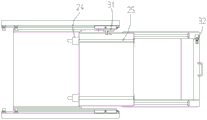
For improving the intensity of this charging tray subassembly 20, be close to at this first mounting panel 21 the side upper surface of material loading station 30 sets firmly first slider 24, and this first slider 24 can set up two sets ofly, and these two sets of first slider 24 set up along the vertical direction interval of first mounting panel 21 moving direction, and equal sliding connection has first rail 25 on these two sets of first slider 24, and this first rail 25 links firmly in this second mounting panel 22 lower surface, because this first slider 24 is located first mounting panel 21 and is close to the side upper surface of material loading station 30 to make this second mounting panel 22 can move to more strokes to material loading station 30 direction.
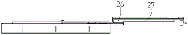
The upper surface of the side end close to the feeding station 30 on the second mounting plate 22 is fixedly provided with the second sliding blocks 26, the second sliding blocks 26 can be arranged in two groups, the two groups of second sliding blocks 26 are arranged at intervals along the vertical direction of the moving direction of the second mounting plate 22, the two groups of second sliding blocks 26 are connected with the second line rails 27 in a sliding mode, the second line rails 27 are fixedly arranged on the lower surface of the third mounting plate 23, and the second sliding blocks 26 are located on the upper surface of the side end close to the feeding station 30 on the second mounting plate 22, so that the third mounting plate 23 can move to more strokes towards the feeding station 30, and in the embodiment, the second mounting plate 22 and the third mounting plate 23 are connected by adopting a line rail sliding block structure, so that the strength of the tray assembly 20 is improved.
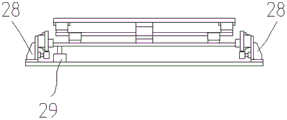
In another embodiment, as shown in fig. 3-5, the tray assembly 20 further includes two support seats 28, the support seats 28 are fixedly connected to the frame 10, two sets of the support seats 28 can be respectively fixedly connected to two side ends of the frame 10, the first mounting plate 21 is disposed between the two sets of the support seats 28, a third sliding block 214 is fixedly connected to each side end of the first mounting plate 21, a third track 213 is fixedly connected to each side end of the two sets of the support seats 28, the third sliding block 214 is slidably connected to the third track 213, a driving member 29 is fixedly disposed on the support seat 28, the driving member 29 is configured to drive the first mounting plate 21 to move toward the conveying station 40, so that the third mounting plate 23 moves to the conveying station 40
In this embodiment, the driving member 29 may be a cylinder, one end of the cylinder is fixed on the support 28, and the other end of the cylinder is connected to the first mounting plate 21, and when the cylinder is operated, the first mounting plate 21, the second mounting plate 22 and the third mounting plate 23 are driven to move toward the carrying station 40, so that the third mounting plate 23 moves out of the rack 10 to the carrying station 40, thereby facilitating the transfer of the workpiece on the third mounting plate 23 to the setting station.
Furthermore, a plurality of grooves 231 are formed in the third mounting plate 23, and the plurality of grooves 231 are used for placing workpieces respectively, so that the workpieces are prevented from falling off from the third mounting plate 23 in the moving process of the third mounting plate 23.
In order to prevent the driving member 29 from moving relatively between the first mounting plate 21, the second mounting plate 22 and the third mounting plate 23 when driving the first mounting plate 21, in another embodiment, a fixture block 50 is fixedly disposed on the first mounting plate 21, a groove is formed in the fixture block 50, the fixture block 50 is preferably disposed at a side end of the first mounting plate 21 close to the feeding station 30, an elastic plunger 60 is fixedly disposed on the third mounting plate 23, the elastic plunger 60 is preferably disposed at a side end of the third mounting plate 23 close to the feeding station 30, and the elastic plunger 60 can move along with the third mounting plate 23 and be clamped into the groove in the fixture block 50, so as to fixedly connect the first mounting plate 21, the second mounting plate 22 and the third mounting plate 23 relatively.
In this embodiment, since the first mounting plate 21, the second mounting plate 22 and the third mounting plate 23 are fixed relatively, when the driving member 29 drives the first mounting plate 21 to move, the driving member simultaneously drives the second mounting plate 22 and the third mounting plate 23 to move, so as to move the third mounting plate 23 to the carrying station 40.
In another embodiment, to control the moving stroke of the second mounting plate 22 on the first mounting plate 21, a first stopper 211 is fixedly attached to the upper surface of the side end of the first mounting plate 21 close to the loading station 30, a second stopper 221 is fixedly attached to the side end of the second mounting plate 22 close to the carrying station 40, the first stopper 211 and the second stopper 221 are disposed opposite to each other, when the second mounting plate 22 moves toward the loading station 30, the second stopper 221 on the second mounting plate 22 will abut against the first stopper 211, so as to prevent the second mounting plate 22 from moving further toward the loading station 30.
In addition, a third stopper 212 is fixedly connected to the upper surface of the side end of the first mounting plate 21 close to the carrying station 40, the third stopper 212 is disposed opposite to the second stopper 221, when the second mounting plate 22 moves toward the carrying station 40, the second stopper 221 on the second mounting plate 22 will abut against the third stopper 212, so as to prevent the second mounting plate 22 from moving toward the carrying station 40, in this embodiment, the second stopper 221 is located between the third stopper 212 and the first stopper 211, so as to control the moving stroke of the second mounting plate 22 on the first mounting plate 21.
In another embodiment, to control the moving stroke of the third mounting plate 23 on the second mounting plate 22, a fourth limiting block 222 is fixedly connected to the upper surface of the side end of the second mounting plate 22 close to the feeding station 30, a fifth limiting block 232 is fixedly connected to the side end of the third mounting plate 23 far from the feeding station 30, the fourth limiting block 222 and the fifth limiting block 232 are disposed opposite to each other, when the third mounting plate 23 moves toward the feeding station 30, the fifth limiting block 232 on the third mounting plate 23 will abut against the fourth limiting block 222, so as to limit the third mounting plate 23 to continue moving toward the feeding station 30.
The second stopper 221 is fixedly connected to the side end surface of the second mounting plate 22 close to the carrying station 40, the fourth stopper 232 is disposed opposite to the second stopper 221, and when the third mounting plate 23 slides on the surface of the second mounting plate 22 and moves toward the carrying station 40, the fourth stopper 232 on the third mounting plate 23 will abut against the second stopper 221, so as to limit the third mounting plate 23 from moving toward the carrying station 40.
In this embodiment, the second limiting block 221 and the fourth limiting block 222 are fixed at two side ends of the second mounting plate 22, and the fourth limiting block 232 is located between the second limiting block 221 and the fourth limiting block 222, so as to limit the moving stroke of the third mounting plate 23 on the surface of the second mounting plate 22.
The present invention has been described in connection with specific embodiments, but it should be clear to a person skilled in the art that these descriptions are intended to be illustrative and not limiting to the scope of the invention. Various modifications and adaptations of the present invention may occur to those skilled in the art, which are within the scope of the present invention, based on the spirit and principles of the present invention.
Claims (10)
1. A loading device, comprising:
a frame;
the feeding station and the carrying station are respectively positioned in the outer side areas of two side ends of the rack, the feeding station is used for loading workpieces on the feeding disc assembly, and the carrying station is used for transferring the workpieces in the feeding disc assembly to a set station;
and at least two groups of the charging tray assemblies are arranged in the rack at intervals along the vertical direction.
2. The loading device of claim 1, wherein the tray assembly comprises:
the first mounting plate is arranged in the rack;
the second mounting plate is horizontally and slidably connected to the upper surface of the first mounting plate;
the third mounting plate is horizontally and slidably connected to the upper surface of the second mounting plate;
wherein the third mounting plate is movable completely to an outer region of the frame to move the third mounting plate to the loading station.
3. The loading device according to claim 2, characterized in that:
a first sliding block is fixedly arranged on the upper surface of the side end, close to the feeding station, of the first mounting plate;
and a first line rail is fixedly arranged on the lower surface of the second mounting plate and is in sliding connection with the first sliding block.
4. A loading device according to claim 2 or 3, characterized in that:
a second sliding block is fixedly arranged on the upper surface of the side end, close to the feeding station, of the second mounting plate;
and a second line rail is fixedly arranged on the lower surface of the third mounting plate and is in sliding connection with the second sliding block.
5. The loading device according to claim 4, characterized in that:
and a plurality of grooves are formed in the upper surface of the third mounting plate and used for placing the workpiece.
6. The loading device according to claim 2, characterized in that:
the charging tray assembly further comprises a support, the support is fixedly connected in the rack, and the first mounting plate is horizontally connected to the support in a sliding manner;
and a driving piece is fixedly arranged on the support and used for driving the first mounting plate to move towards the conveying station so as to enable the third mounting plate to move to the conveying station.
7. The loading device according to claim 2, characterized in that:
a first limiting block is fixedly connected to the upper surface of the side end, close to the feeding station, of the first mounting plate, a second limiting block is fixedly connected to the side end, close to the carrying station, of the second mounting plate, and the first limiting block and the second limiting block are arranged oppositely;
a third limiting block is fixedly connected to the upper surface of the side end, close to the carrying station, of the first mounting plate, and the third limiting block and the second limiting block are arranged oppositely;
the second limiting block is located between the third limiting block and the first limiting block, and the first limiting block and the third limiting block are used for limiting the horizontal movement stroke of the second mounting plate on the first mounting plate.
8. The loading device according to claim 2, characterized in that:
a fourth limiting block is fixedly connected to the upper surface of the side end, close to the feeding station, of the second mounting plate, a fifth limiting block is fixedly connected to the side end, far away from the feeding station, of the third mounting plate, and the fourth limiting block and the fifth limiting block are arranged oppositely;
a second limiting block is fixedly connected to the surface of the side end, close to the carrying station, of the second mounting plate, and the fourth limiting block is arranged opposite to the second limiting block;
the fourth limiting block is located between the second limiting block and the fourth limiting block, and the second limiting block and the fourth limiting block are used for limiting the moving stroke of the second mounting plate.
9. The loading device according to claim 2, characterized in that:
a clamping block is fixedly arranged on the first mounting plate, and an elastic plunger is fixedly arranged on the third mounting plate;
the elastic plunger can be clamped into the clamping block and is used for fixedly connecting the first mounting plate, the second mounting plate and the third mounting plate relatively.
10. The loading device according to claim 6, characterized in that:
the two groups of supports are arranged at intervals and are fixedly connected to the rack respectively, and third linear rails are fixedly connected to the side ends of the two groups of supports;
the first mounting plate sets up in two sets of between the support, and be in first mounting plate both sides end all links firmly the third slider, the third slider set up in first mounting plate is close to the side of material loading station, the third slider with third track sliding connection.
Priority Applications (1)
| Application Number | Priority Date | Filing Date | Title |
|---|---|---|---|
| CN202021717417.7U CN213010613U (en) | 2020-08-18 | 2020-08-18 | Feeding device |
Applications Claiming Priority (1)
| Application Number | Priority Date | Filing Date | Title |
|---|---|---|---|
| CN202021717417.7U CN213010613U (en) | 2020-08-18 | 2020-08-18 | Feeding device |
Publications (1)
| Publication Number | Publication Date |
|---|---|
| CN213010613U true CN213010613U (en) | 2021-04-20 |
Family
ID=75468335
Family Applications (1)
| Application Number | Title | Priority Date | Filing Date |
|---|---|---|---|
| CN202021717417.7U Active CN213010613U (en) | 2020-08-18 | 2020-08-18 | Feeding device |
Country Status (1)
| Country | Link |
|---|---|
| CN (1) | CN213010613U (en) |
Cited By (1)
| Publication number | Priority date | Publication date | Assignee | Title |
|---|---|---|---|---|
| CN113639702A (en) * | 2021-10-13 | 2021-11-12 | 江苏莱克智能电器有限公司 | Automatic system and method for machining and flatness detection |
-
2020
- 2020-08-18 CN CN202021717417.7U patent/CN213010613U/en active Active
Cited By (1)
| Publication number | Priority date | Publication date | Assignee | Title |
|---|---|---|---|---|
| CN113639702A (en) * | 2021-10-13 | 2021-11-12 | 江苏莱克智能电器有限公司 | Automatic system and method for machining and flatness detection |
Similar Documents
| Publication | Publication Date | Title |
|---|---|---|
| CN215325537U (en) | Material machine is grabbed to panel | |
| CN213010613U (en) | Feeding device | |
| CN210943854U (en) | Transfer system | |
| CN113104563B (en) | Loading jig and jig backflow device | |
| CN214114068U (en) | Single-power dislocation cutting device | |
| CN213079804U (en) | Riveting device for elevator fixing plate assembly | |
| CN210837682U (en) | Novel solid brilliant machine material receiving system | |
| CN211419325U (en) | Flexible clamping and holding device suitable for multiple vehicle types | |
| CN212371446U (en) | Laser cutting machine change table | |
| CN215159007U (en) | Tray clamp and stack dish device | |
| CN210223981U (en) | Automatic feeding mechanism of semiconductor packaging all-in-one machine | |
| CN217755399U (en) | Automatic feeding device for screw rod spring | |
| CN219751229U (en) | Overturning stacking device | |
| CN213677358U (en) | Feeding platform capable of being switched in rapid circulation mode | |
| CN211469990U (en) | Moving iron feeding assembly of electromagnetic valve | |
| CN213230503U (en) | Battery voltage login equipment location and move and carry mechanism | |
| CN214358865U (en) | Hoisting stacking equipment for storage | |
| CN215905393U (en) | Automatic feeding device for connecting and assembling double workpieces | |
| CN220617497U (en) | Automatic feeding device | |
| CN217946817U (en) | Workpiece circulating feeding device | |
| CN218448022U (en) | Assembly equipment of battery device | |
| CN218619100U (en) | Plane type material transferring platform | |
| CN217478463U (en) | Clamp for battery cell and cover plate, carrying device and carrying system | |
| CN215923697U (en) | Move and carry structure and production line | |
| CN210456591U (en) | High-speed liquid crystal screen module switching device |
Legal Events
| Date | Code | Title | Description |
|---|---|---|---|
| GR01 | Patent grant | ||
| GR01 | Patent grant |