CN213005652U - Violently indulge integrative cutting equipment - Google Patents
Violently indulge integrative cutting equipment Download PDFInfo
- Publication number
- CN213005652U CN213005652U CN202021206566.7U CN202021206566U CN213005652U CN 213005652 U CN213005652 U CN 213005652U CN 202021206566 U CN202021206566 U CN 202021206566U CN 213005652 U CN213005652 U CN 213005652U
- Authority
- CN
- China
- Prior art keywords
- feeding
- cutting
- roller
- transverse cutting
- transverse
- Prior art date
- Legal status (The legal status is an assumption and is not a legal conclusion. Google has not performed a legal analysis and makes no representation as to the accuracy of the status listed.)
- Active
Links
- 238000005520 cutting process Methods 0.000 title claims abstract description 251
- 239000000463 material Substances 0.000 claims abstract description 50
- 239000002699 waste material Substances 0.000 claims abstract description 47
- 230000000903 blocking effect Effects 0.000 claims description 73
- 238000007599 discharging Methods 0.000 claims description 72
- 238000009434 installation Methods 0.000 claims description 23
- 230000005540 biological transmission Effects 0.000 claims description 18
- 230000001360 synchronised effect Effects 0.000 claims description 14
- 230000006835 compression Effects 0.000 claims description 3
- 238000007906 compression Methods 0.000 claims description 3
- 238000004519 manufacturing process Methods 0.000 description 6
- 230000007547 defect Effects 0.000 description 3
- 230000000694 effects Effects 0.000 description 3
- 238000012986 modification Methods 0.000 description 2
- 230000004048 modification Effects 0.000 description 2
- 238000006467 substitution reaction Methods 0.000 description 2
- 239000010425 asbestos Substances 0.000 description 1
- 238000000034 method Methods 0.000 description 1
- 230000001737 promoting effect Effects 0.000 description 1
- 229910052895 riebeckite Inorganic materials 0.000 description 1
Images




Landscapes
- Nonmetal Cutting Devices (AREA)
Abstract
The utility model discloses a violently indulge integrative cutting means, including cylinder pay-off module, ejection of compact conveying module and set up the violently integrative module that cuts of indulging between cylinder pay-off module and ejection of compact conveying module, violently indulge integrative cutting module including cut the module frame and set up at the preceding fender material device that cuts in the module frame, indulge and cut branch strip device, layer board guider, crosscut device and keep off the waste material device, indulge and cut the strip device and include a plurality of circle cutters, the crosscut device includes the crosscut knife subassembly, still be provided with circle cutter drive arrangement and crosscut cutter drive arrangement in cutting the module frame, circle cutter drive arrangement and crosscut cutter drive arrangement are used for the drive respectively circle cutter and crosscut the motion is done to circle cutter and crosscut knife subassembly. The horizontal and vertical integrated cutting equipment has the advantages that the structure is simple, the occupied space is small, the equipment cost is saved, the automation degree is high, the working efficiency is high, the working strength is low, the labor cost is saved and the like, which are not possessed by the prior art.
Description
Technical Field
The utility model relates to a sheet cuts processing equipment, especially a violently indulge integrative cutting equipment.
Background
For some sheet materials, such as asbestos paper, etc., the sheet materials need to be transversely and longitudinally cut during production, application, etc. to achieve miniaturization.
The existing sheet cutting equipment is generally complex, has the defects of difficult manufacture, large volume and high implementation cost, and needs to transfer and process the transverse cutting and longitudinal cutting of the sheet in two pieces of equipment, thereby seriously affecting the production efficiency and also increasing the labor cost and the labor intensity.
In view of the above, the present invention provides a new technical solution to solve the existing technical drawbacks.
SUMMERY OF THE UTILITY MODEL
In order to overcome the not enough of prior art, the utility model provides a violently indulge integrative cutting equipment has solved the technical defect such as the structure complicacy that prior art exists, bulky, equipment cost is high, production efficiency is low, the cost of labor is high, intensity of labour is high.
The utility model provides a technical scheme that its technical problem adopted is:
the utility model provides a violently indulge integrative cutting means, includes cylinder pay-off module, ejection of compact conveying module and sets up the integrative module that cuts of violently indulging between cylinder pay-off module and ejection of compact conveying module, violently indulge integrative cutting module including cut the module frame and set up preceding fender material device, rip cutting slitting device, layer board guider, crosscut device and fender waste material device in cutting the module frame, rip cutting slitting device includes a plurality of circle cutters, the crosscut device includes the crosscut knife subassembly, still be provided with circle cutter drive arrangement and crosscut knife drive arrangement in cutting the module frame, circle cutter drive arrangement and crosscut knife drive arrangement are used for the drive respectively circle cutter and crosscut knife subassembly are the cutting motion.
As an improvement of the above technical solution, the transverse cutting device includes a transverse cutting device bottom plate fixed on the cutting module frame and transverse cutting device side plates fixedly disposed on both sides of the transverse cutting device bottom plate, transverse cutter chutes are disposed on both the two transverse cutting device side plates, transverse cutter sliders are disposed in the transverse cutter chutes, an upper transverse cutter is fixedly disposed between the two transverse cutter sliders, a lower transverse cutter matched with the upper transverse cutter is further disposed on the transverse cutting device bottom plate, the upper transverse cutter and the lower transverse cutter constitute the transverse cutter assembly, an output end of the transverse cutter driving device is connected to the transverse cutter sliders and can drive the transverse cutter sliders to slide in the transverse cutter chutes, and the transverse cutter sliders drive the upper transverse cutter to move and cooperate with the lower transverse cutter to perform transverse cutting operation on the material to be cut.
As a further improvement of the technical scheme, a transverse cutting first rubber covered roller, a transverse cutting second rubber covered roller, a transverse cutting first guide roller and a transverse cutting second guide roller are further arranged between the two transverse cutting device side plates, the transverse cutting first rubber covered roller and the transverse cutting second rubber covered roller are used in a matched mode, the transverse cutting first guide roller and the transverse cutting second guide roller are used in a matched mode, a first sliding groove and a second sliding groove are formed in each transverse cutting device side plate, a top limiting plate is arranged at the top of each transverse cutting device side plate, a first sliding block is arranged in each first sliding groove, two ends of each transverse cutting first rubber covered roller are installed on the two transverse cutting device side plates through bearings, the end portion of each transverse cutting second rubber covered roller is installed on the first sliding block through a bearing, a compression spring is arranged between each first sliding block and the top limiting plate, a second sliding block and a third sliding block are arranged in each second sliding groove, and, the end part of the transverse cutting second guide roller is installed on a third sliding block through a bearing, a first distance adjusting bolt is arranged between the second sliding block and the top limiting plate, a second distance adjusting bolt is arranged between the third sliding block and the top limiting plate, and a first sliding block connecting rod is arranged between the two first sliding blocks.
As a further improvement of the above technical solution, a lower cross cutting knife holder is arranged on a bottom plate of the cross cutting device, an upper cross cutting knife holder is arranged between two cross cutting knife sliders, the lower cross cutting knife is fixedly mounted on the lower cross cutting knife holder, the upper cross cutting knife is fixed on the upper cross cutting knife holder, a slider connecting rod is fixedly connected between the two cross cutting knife sliders, an upper cutting knife limiting rod is arranged on the slider connecting rod, an upper cutting knife limiting plate is fixedly arranged on the upper cross cutting knife, a limiting groove is formed on the upper cutting knife limiting plate, and a free end of the upper cutting knife limiting rod extends into the limiting groove and can move within a limiting range of the limiting groove.
As a further improvement of the above technical solution, the cross-cutting knife driving device includes a driving motor, and a first installation shaft, a second installation shaft, and a third installation shaft installed on the cutting module frame, the output end of the driving motor is provided with a first driving pulley, the first installation shaft is provided with a first driven pulley and a second driving pulley, the second installation shaft is provided with a second driven pulley, a first belt is wound between the first driving pulley and the first driven pulley, a second belt is wound between the second driving pulley and the second driven pulley, the second installation shaft is provided with an eccentric wheel, the outer edge of the eccentric wheel is sleeved with an eccentric wheel sleeve, the eccentric wheel sleeve is provided with a first connecting rod, the third installation shaft is provided with a first oscillating rod and a second oscillating rod, the free end of the first connecting rod is hinged to the free end of the first oscillating rod, the free end of the second swing rod is hinged to a second connecting rod, and the free end of the second connecting rod is hinged to the lower end of the sliding block of the transverse cutter.
As a further improvement of the above technical scheme, the slitting and slitting device comprises two slitting device side plates fixed on a cutting module frame, and a first circular knife mounting roller and a second circular knife mounting roller which are arranged between the two slitting device side plates, wherein a plurality of circular knives are arranged on the second circular knife mounting roller, a cutter matching wheel matched with the circular knives in use is arranged on the first circular knife mounting roller, a driving wheel is arranged at one end of the first circular knife mounting roller, the output end of the circular knife driving device is connected to the driving wheel and drives the first circular knife mounting roller to rotate through the driving wheel, and the first circular knife mounting roller drives the second circular knife mounting roller to rotate through a gear set and further drives the circular knives and the cutter matching wheel to rotate so as to realize the slitting function.
As a further improvement of the technical scheme, a longitudinal cutting first rubber roller and a longitudinal cutting second rubber roller are further arranged between the two longitudinal cutting device side plates, a third sliding groove and a fourth sliding groove are formed in each longitudinal cutting device side plate, a longitudinal cutting top cover plate is arranged at the top of each longitudinal cutting device side plate, a fourth sliding block capable of sliding in the third sliding groove is arranged in each third sliding groove, two ends of each longitudinal cutting first rubber roller are mounted on the longitudinal cutting device side plates through bearings, two ends of each longitudinal cutting second rubber roller are mounted on the fourth sliding block through bearings, and a fourth sliding block connecting rod is arranged between the two fourth sliding blocks; the rubber belt cutting device is characterized in that a fifth sliding block capable of sliding in the fourth sliding groove is arranged in the fourth sliding groove, two ends of the first circular knife installation roller are installed on the longitudinal cutting device side plate through bearings, two ends of the second circular knife installation roller are installed on the fifth sliding block through bearings, height fine adjustment devices are arranged among the fourth sliding block, the fifth sliding block and the longitudinal cutting top cover plate, and a transmission device is arranged between the end portion of the longitudinal cutting first rubber roller and the first circular knife installation roller.
As a further improvement of the above technical scheme, the front material stopping device comprises a front material stopping device support fixed on the cutting module rack, and a front material stopping driving cylinder and a front material stopping guide pillar which are arranged on the front material stopping device support, wherein a front material stopping plate is fixedly arranged at the lower end of the front material stopping guide pillar, and the output end of the front material stopping driving cylinder is fixedly connected to the front material stopping plate and can drive the front material stopping plate to move in the guiding direction of the front material stopping guide pillar so as to realize the material stopping function.
As a further improvement of the above technical scheme, the support plate guiding device comprises two guiding device supports directly or indirectly fixed on the cutting module frame and two lower support plate mounting rods and two upper support plate mounting rods arranged on the guiding device supports, a lower guiding support plate is fixedly arranged on the lower support plate mounting rods, a plurality of upper support plate mounting frames are arranged on the upper support plate mounting rods, an upper guiding support plate is arranged on the upper support plate mounting frames, and a gap through which a cut material can pass is formed between the upper guiding support plate and the lower guiding support plate.
As a further improvement of the technical proposal, the waste material blocking device comprises two waste material blocking brackets fixed on the cutting module frame and a waste material blocking guide post arranged between the two waste material blocking brackets, the waste material blocking guide post is provided with a waste material blocking slide block which can slide on the waste material blocking guide post, the waste material blocking slide block is fixedly provided with a waste material baffle plate, the waste blocking bracket is also provided with an adjusting screw rod, the waste blocking slide block is provided with an adjusting screw hole matched with the adjusting screw rod, one end of the adjusting screw rod is connected in the adjusting screw hole in a threaded manner, the other end of the adjusting screw rod is arranged on the waste material blocking bracket through a bearing, the outer end of the adjusting screw rod is provided with a waste material blocking adjusting hand wheel, the waste blocking adjusting hand wheel can drive the adjusting screw rod to rotate and further drive the waste blocking sliding block to slide on the waste blocking guide column so as to adjust the blocking range of the waste blocking plate.
As a further improvement of the above technical solution, the roller feeding module comprises a feeding module mounting frame, the feeding module mounting frame is provided with a feeding roller driving motor, a feeding intermediate transmission shaft and a plurality of feeding rollers arranged in parallel, the output end of the feeding roller driving motor is provided with a feeding driving synchronizing wheel, one end of the feeding intermediate transmission shaft is provided with a feeding driven synchronizing wheel, a feeding synchronous belt is wound between the feeding driving synchronizing wheel and the feeding driven synchronizing wheel, the feeding intermediate transmission shaft is provided with a number of feeding driving belt pulleys matching the number of the feeding rollers, the feeding roller is provided with a feeding driven belt pulley, a feeding belt is wound between the feeding driving belt pulley and the feeding driven belt pulley in a one-to-one correspondence manner, the feeding roller driving motor can drive the feeding intermediate transmission shaft to rotate through the feeding driving synchronizing wheel, the feeding driven synchronizing wheel and the feeding synchronous belt, the feeding middle transmission shaft drives the feeding roller to rotate through the feeding driving belt pulley, the feeding driven belt pulley and the feeding belt so as to realize the feeding function.
As a further improvement of the above technical scheme, the roller feeding module further comprises a discharging baffle device and a feeding baffle device;
as a further improvement of the technical proposal, the discharging baffle device comprises a discharging baffle guide post fixed on the feeding module mounting rack, a first discharging baffle slide block and a second discharging baffle slide block which are arranged on the discharging baffle guide post and can slide on the discharging baffle guide post, the first discharging baffle sliding block and the second discharging baffle sliding block are respectively provided with a first discharging baffle and a second discharging baffle, the feeding module mounting frame is also provided with a first discharging baffle adjusting screw and a second discharging baffle adjusting screw, the first discharging baffle adjusting screw and the second discharging baffle adjusting screw are respectively in threaded connection with a first discharging baffle slider and a second discharging baffle slider, and the outer ends of the first discharging baffle adjusting screw and the second discharging baffle adjusting screw are respectively provided with a first discharging baffle adjusting hand wheel and a second discharging baffle adjusting hand wheel;
as a further improvement of the above technical solution, the feeding baffle device includes a feeding baffle guide pillar fixed on the feeding module mounting rack, and a first feeding baffle slider and a second feeding baffle slider which are mounted on the feeding baffle guide pillar and can slide on the feeding baffle guide pillar, the first feeding baffle slider and the second feeding baffle slider are respectively mounted with a first feeding baffle and a second feeding baffle, the feeding module mounting rack is further provided with a feeding baffle driving cylinder and a feeding baffle adjusting screw, an output end of the feeding baffle driving cylinder is connected to the first feeding baffle slider and can drive the first feeding baffle slider to slide on the feeding baffle guide pillar, an inner end of the feeding baffle adjusting screw is in threaded connection with the second feeding baffle slider, and an outer end of the feeding baffle adjusting screw is provided with a feeding baffle adjusting hand wheel.
As the further improvement of above-mentioned technical scheme, ejection of compact conveying module includes ejection of compact module mounting bracket and sets up ejection of compact driving motor, exit conveyor drive roll, exit conveyor driven voller, exit conveyor auxiliary roll on ejection of compact module mounting bracket, around being equipped with exit conveyor between exit conveyor drive roll and the exit conveyor driven voller, exit drive motor's output is provided with ejection of compact initiative synchronizing wheel exit conveyor drive roll's one end is provided with ejection of compact driven synchronizing wheel, around being equipped with ejection of compact hold-in range between ejection of compact initiative synchronizing wheel and the ejection of compact driven synchronizing wheel, ejection of compact driving motor accessible ejection of compact initiative synchronizing wheel, ejection of compact driven synchronizing wheel and ejection of compact hold-in range drive exit conveyor drive roll rotate and further cooperate exit conveyor driven voller to rotate.
The utility model has the advantages that: the utility model provides a violently indulge integrative cutting equipment, this kind violently indulge integrative cutting equipment can realize crosscut and rip cutting function through rip cutting slitting device and crosscut device in an equipment, has simple structure, small advantage, effectively promotes production efficiency and reduces intensity of labour when practical application, and the cost of labor is lower, saves equipment cost, helps promoting the productivity effect of enterprise.
In a word, this kind of violently indulge integrative cutting equipment has solved the technical defect that prior art exists that the structure is complicated, bulky, equipment cost is high, production efficiency is low, the cost of labor is high, intensity of labour is high.
Drawings
The present invention will be further explained with reference to the drawings and examples.
FIG. 1 is a schematic assembly view of the present invention;
FIG. 2 is an assembly view of the middle transverse and longitudinal integrated cutting module of the present invention;
fig. 3 is an assembly schematic view of the crosscutting apparatus of the present invention;
fig. 4 is another schematic assembly view of the cross cutting device of the present invention;
FIG. 5 is a sectional view taken along line A-A of FIG. 4;
FIG. 6 is an assembly view of the slitting and slitting device of the present invention;
FIG. 7 is another schematic assembly view of the slitting and slitting apparatus of the present invention;
FIG. 8 is a sectional view taken in the direction B-B in FIG. 7;
fig. 9 is an assembly schematic view of the middle front material blocking device of the present invention;
fig. 10 is an assembly view of the pallet guide of the present invention;
FIG. 11 is an assembly view of the waste blocking device of the present invention;
fig. 12 is an assembly view of the cross-cutter driving device of the present invention;
fig. 13 is an assembly view of the roller feed module of the present invention;
fig. 14 is an assembly schematic view of the discharge baffle device of the present invention;
FIG. 15 is an assembled view of the feed baffle assembly of the present invention;
FIG. 16 is an assembly schematic of the outfeed transfer module of the present invention;
fig. 17 is a schematic view of the internal assembly of the discharging transfer module of the present invention.
Detailed Description
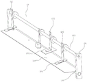
The conception, the specific structure, and the technical effects produced by the present invention will be clearly and completely described below in conjunction with the embodiments and the accompanying drawings to fully understand the objects, the features, and the effects of the present invention. Obviously, the described embodiments are only a part of the embodiments of the present invention, and not all embodiments, and other embodiments obtained by those skilled in the art without inventive labor based on the embodiments of the present invention all belong to the protection scope of the present invention. In addition, all the connection/connection relations referred to in the patent do not mean that the components are directly connected, but mean that a better connection structure can be formed by adding or reducing connection auxiliary components according to specific implementation conditions. The technical characteristics of the utility model can be combined interactively on the premise of not conflicting with each other, refer to fig. 1
The utility model provides a violently indulge integrative cutting means, includes cylinder pay-off module 5, ejection of compact conveying module 6 and sets up the integrative module that cuts of violently indulging between cylinder pay-off module 5 and ejection of compact conveying module 6, violently indulge integrative cutting module including cut module frame 1 and set up cutting preceding dam device 11, rip cutting on module frame 1 and divide strip device 2, layer board guider 12, crosscut device 3 and keep off waste material device 13, rip cutting divides strip device 2 to include a plurality of circle cutters 201, crosscut device 3 includes the crosscut knife subassembly, still be provided with circle cutter drive arrangement and crosscut cutter drive arrangement 4 on cutting module frame 1, circle cutter drive arrangement and crosscut cutter drive arrangement 4 are used for the drive respectively circle cutter 201 and crosscut the motion is done to the crosscut cutter subassembly.
Detailed implementation the utility model discloses in the time, the material 10 that needs the cutting enters into in the cutting module in the past dam device 11, the material 10 that needs the cutting at first is cut by slitting device 2 and becomes predetermined width, cut by crosscut device 3 again and become predetermined length, realize slitting, the function of slitting integrative cutting, can accomplish slitting, the crosscut in an equipment, save equipment cost, the transport work between the different equipment has been eliminated, work efficiency is higher, labor intensity and cost of labor are reduced.
Preferably, the transverse cutting device 3 comprises a transverse cutting device bottom plate 311 fixed on the cutting module frame 1 and transverse cutting device side plates 312 fixedly arranged on two sides of the transverse cutting device bottom plate 311, a transverse cutting knife sliding slot 321 is arranged on each of the two transverse cutting device side plates 312, a transverse cutter sliding block 322 is arranged in the transverse cutter sliding chute 321, an upper transverse cutter 331 is fixedly arranged between the two transverse cutter sliding blocks 322, the bottom plate 311 of the transverse cutting device is also provided with a lower transverse cutting knife 332 matched with the upper transverse cutting knife 331, the upper cross cutter 331 and the lower cross cutter 332 constitute the cross cutter assembly, the output end of the cross cutter driving device 4 is connected to the cross cutter slider 322 and can drive the cross cutter slider 322 to slide in the cross cutter runner 321, the cross cutting knife slider 322 drives the upper cross cutting knife 331 to move and cooperates with the lower cross cutting knife 332 to perform a cross cutting operation on the material 10 to be cut.
Preferably, a transverse cutting first rubber covered roller 341, a transverse cutting second rubber covered roller 342, a transverse cutting first guide roller 351 and a transverse cutting second guide roller 352 are further arranged between the two transverse cutting device side plates 312, the transverse cutting first rubber covered roller 341 and the transverse cutting second rubber covered roller 342 are used in a matched mode, the transverse cutting first guide roller 351 and the transverse cutting second guide roller 352 are used in a matched mode, a first sliding groove 313 and a second sliding groove 314 are formed in the transverse cutting device side plates 312, a top limiting plate 315 is arranged at the top of the transverse cutting device side plates 312, a first sliding block 316 is arranged in the first sliding groove 313, two ends of the transverse cutting first rubber covered roller 341 are mounted on the two transverse cutting device side plates 312 through bearings, an end of the transverse cutting second rubber covered roller 342 is mounted on the first sliding block 316 through a bearing, a compression spring 317 is arranged between the first sliding block 316 and the top limiting plate 315, a second sliding block 318 and, the end part of the transverse first guide roller 351 is mounted on the second sliding block 318 through a bearing, the end part of the transverse second guide roller 352 is mounted on the third sliding block 319 through a bearing, a first distance adjusting bolt 361 is arranged between the second sliding block 318 and the top limiting plate 315, a second distance adjusting bolt 362 is arranged between the third sliding block 319 and the top limiting plate 315, and a first sliding block connecting rod 363 is arranged between the two first sliding blocks 316.
Preferably, a lower cross-cutting knife seat 323 is arranged on the bottom plate 311 of the cross-cutting device, an upper cross-cutting knife seat 327 is arranged between the two cross-cutting knife sliders 322, the lower cross-cutting knife 332 is fixedly mounted on the lower cross-cutting knife seat 323, the upper cross-cutting knife 331 is fixed on the upper cross-cutting knife seat 327, a slider connecting rod 324 is fixedly connected between the two cross-cutting knife sliders 322, an upper cutting knife limiting rod 325 is arranged on the slider connecting rod 324, an upper cutting knife limiting plate 326 is fixedly arranged on the upper cross-cutting knife 331, a limiting groove is formed on the upper cutting knife limiting plate 326, and a free end of the upper cutting knife limiting rod 325 extends into the limiting groove and can move within the limiting range of the limiting groove.
Preferably, the cross cutting knife driving device 4 comprises a driving motor, and a first installation shaft 41, a second installation shaft 42 and a third installation shaft 43 which are installed on the cutting module frame 1, wherein an output end of the driving motor is provided with a first driving pulley, the first installation shaft 41 is provided with a first driven pulley 411 and a second driving pulley 412, the second installation shaft 42 is provided with a second driven pulley 421, a first belt is wound between the first driving pulley and the first driven pulley 411, a second belt is wound between the second driving pulley 412 and the second driven pulley 421, the second installation shaft 42 is provided with an eccentric wheel 422, an eccentric wheel sleeve 423 is sleeved on an outer edge of the eccentric wheel 422, the eccentric wheel sleeve 423 is provided with a first connecting rod 44, and the third installation shaft 43 is provided with a first swinging rod 431 and a second swinging rod 432, the free end of the first connecting rod 44 is hinged to the free end of the first swinging rod 431, the free end of the second swinging rod 432 is hinged to the second connecting rod 45, and the free end of the second connecting rod 45 is hinged to the lower end of the transverse cutter sliding block 322.
Preferably, the slitting and slitting device 2 comprises two slitting device side plates 21 fixed on the cutting module frame 1, a first circular knife mounting roller 221 and a second circular knife mounting roller 222 arranged between the two slitting device side plates 21, a plurality of circular knives 201 are arranged on the second circular knife mounting roller 222, a cutter matching wheel 202 matched with the circular knives 201 for use is arranged on the first circular knife mounting roller 221, a driving wheel 223 is arranged at one end of the first circular knife mounting roller 221, the output end of the circular knife driving device is connected to the driving wheel 223 and drives the first circular knife mounting roller 221 to rotate through the driving wheel 223, and the first circular knife mounting roller 221 drives the second circular knife mounting roller 222 to rotate through a gear set and further drives the circular knives 201 and the cutter matching wheel 202 to rotate so as to realize the slitting function.
Preferably, a first longitudinal cutting rubber roll 231 and a second longitudinal cutting rubber roll 232 are further arranged between the two lateral plates 21 of the longitudinal cutting device, a third sliding groove 211 and a fourth sliding groove 212 are arranged on the lateral plates 21 of the longitudinal cutting device, a top longitudinal cutting cover plate 213 is arranged at the top of the lateral plates 21 of the longitudinal cutting device, a fourth sliding block 241 capable of sliding in the third sliding groove 211 is arranged in the third sliding groove 211, two ends of the first longitudinal cutting rubber roll 231 are mounted on the lateral plates 21 of the longitudinal cutting device through bearings, two ends of the second longitudinal cutting rubber roll 232 are mounted on the fourth sliding block 241 through bearings, and a fourth sliding block connecting rod 243 is arranged between the two fourth sliding blocks 241; a fifth slider 242 which can slide in the fourth sliding chute 212 is arranged in the fourth sliding chute 212, two ends of the first circular knife installation roller 221 are installed on the longitudinal cutting device side plate 21 through bearings, two ends of the second circular knife installation roller 222 are installed on the fifth slider 242 through bearings, height fine adjustment devices are arranged among the fourth slider 241, the fifth slider 242 and the longitudinal cutting top cover plate 213, and a transmission device is arranged between the end of the longitudinal cutting first rubber roll 231 and the first circular knife installation roller 221.
Preferably, the front material blocking device 11 includes a front material blocking device bracket 111 fixed on the cutting module frame 1, and a front material blocking driving cylinder 112 and a front material blocking guide post 113 arranged on the front material blocking device bracket 111, the lower end of the front material blocking guide post 113 is fixedly provided with a front material blocking plate 114, the output end of the front material blocking driving cylinder 112 is fixedly connected to the front material blocking plate 114 and can drive the front material blocking plate 114 to move in the guiding direction of the front material blocking guide post 113 to realize the material blocking function.
Preferably, the supporting plate guiding device 12 includes two guiding device brackets 121 directly or indirectly fixed on the cutting module frame 1, and a lower supporting plate mounting rod 122 and an upper supporting plate mounting rod 123 arranged on the two guiding device brackets 121, a lower guiding supporting plate 124 is fixedly arranged on the lower supporting plate mounting rod 122, a plurality of upper supporting plate mounting brackets 125 are arranged on the upper supporting plate mounting rod 123, an upper guiding supporting plate 126 is arranged on the upper supporting plate mounting brackets 125, and a gap through which the cut material can pass is formed between the upper guiding supporting plate 126 and the lower guiding supporting plate 124.
Preferably, the waste blocking device 13 comprises two waste blocking brackets 131 fixed on the cutting module frame 1 and a waste blocking guide pillar 132 arranged between the two waste blocking brackets 131, the scrap-catching guide post 132 is provided with a scrap-catching slider 133 slidable on the scrap-catching guide post 132, a waste blocking plate 134 is fixedly arranged on the waste blocking slide block 133, an adjusting screw 135 is also arranged on the waste blocking bracket 131, the waste blocking slide block 133 is provided with an adjusting screw hole matched with the adjusting screw 135, one end of the adjusting screw 135 is connected with the adjusting screw through a thread, the other end of the adjusting screw 135 is arranged on the waste material blocking bracket 131 through a bearing, the outer end of the adjusting screw 135 is provided with a waste material blocking adjusting hand wheel 136, the scrap-retaining adjusting handwheel 136 can drive the adjusting screw 135 to rotate and further drive the scrap-retaining slider 133 to slide on the scrap-retaining guide post 132 so as to adjust the blocking range of the scrap baffle 134.
Preferably, the roller feeding module 5 includes a feeding module mounting frame 51, the feeding module mounting frame 51 is provided with a feeding roller driving motor 52, a feeding intermediate transmission shaft 53 and a plurality of feeding rollers 54 arranged in parallel, the output end of the feeding roller driving motor 52 is provided with a feeding driving synchronizing wheel 551, one end of the feeding intermediate transmission shaft 53 is provided with a feeding driven synchronizing wheel 552, a feeding synchronous belt is wound between the feeding driving synchronizing wheel 551 and the feeding driven synchronizing wheel 552, the feeding intermediate transmission shaft 53 is provided with feeding driving belt pulleys 561 with the number matched with that of the feeding rollers 54, the feeding rollers 54 are provided with feeding driven belt pulleys 562, feeding belts 563 are wound between the feeding driving belt pulleys 561 and the feeding driven belt pulleys 562 in a one-to-one correspondence manner, and the feeding roller driving motor 52 can pass through the feeding driving synchronizing wheels 551, 53, The feeding driven synchronizing wheel 552 and the feeding synchronizing belt drive the feeding middle transmission shaft 53 to rotate, and the feeding middle transmission shaft 53 drives the feeding roller 54 to rotate through the feeding driving belt pulley 561, the feeding driven belt pulley 562 and the feeding belt 563 so as to realize a feeding function.
Preferably, the roller feeding module 5 further comprises a discharging baffle device 7 and a feeding baffle device 8;
preferably, the discharging baffle device 7 comprises a discharging baffle guide post 71 fixed on the feeding module mounting frame 51, and a first discharging baffle slide block 721 and a second discharging baffle slide block 722 which are installed on the discharging baffle guide post 71 and can slide on the discharging baffle guide post 71, the first discharging baffle sliding block 721 and the second discharging baffle sliding block 722 are respectively provided with a first discharging baffle 731 and a second discharging baffle 732, a first discharging baffle adjusting screw 741 and a second discharging baffle adjusting screw 742 are further arranged on the feeding module mounting frame 51, the first discharging baffle adjusting screw 741 and the second discharging baffle adjusting screw 742 are respectively in threaded connection with the first discharging baffle slider 721 and the second discharging baffle slider 722, and a first discharging baffle adjusting hand wheel 751 and a second discharging baffle adjusting hand wheel 752 are respectively arranged at the outer ends of the first discharging baffle adjusting screw 741 and the second discharging baffle adjusting screw 742;
preferably, the feeding baffle device 8 comprises a feeding baffle guide post 81 fixed on the feeding module mounting frame 51, and a first feeding baffle sliding block 821 and a second feeding baffle sliding block 822 mounted on the feeding baffle guide post 81 and capable of sliding on the feeding baffle guide post 81, the first feeding baffle slider 821 and the second feeding baffle slider 822 are respectively provided with a first feeding baffle 831 and a second feeding baffle 832, the feeding module mounting frame 51 is further provided with a feeding baffle driving cylinder 841 and a feeding baffle adjusting screw 842, the output of the feed flapper drive cylinder 841 is connected to the first feed flapper slide block 821 and drives the first feed flapper slide block 821 to slide on the feed flapper guide post 81, the inner end of the feeding baffle adjusting screw 842 is in threaded connection with the second feeding baffle slider 822, and the outer end of the feeding baffle adjusting screw 842 is provided with a feeding baffle adjusting hand wheel 85.
Preferably, the discharging conveying module 6 comprises a discharging module mounting frame 61, a discharging driving motor 62, a discharging conveying belt driving roller 63, a discharging conveying belt driven roller 64 and a discharging conveying belt auxiliary roller 66 which are arranged on the discharging module mounting frame 61, an discharging conveyor belt 65 is wound between the discharging conveyor belt driving roller 63 and the discharging conveyor belt driven roller 64, the output end of the discharging driving motor 62 is provided with a discharging driving synchronizing wheel 671, one end of the discharging conveying belt driving roller 63 is provided with a discharging driven synchronizing wheel 672, a discharging synchronous belt is wound between the discharging driving synchronous wheel 671 and the discharging driven synchronous wheel 672, the discharging driving motor 62 can drive the discharging conveyor belt driving roller 63 to rotate through the discharging driving synchronizing wheel 671, the discharging driven synchronizing wheel 672 and the discharging synchronizing belt and further drive the discharging conveyor belt 65 to run in cooperation with the discharging conveyor belt driven roller 64.
Preferably, a control electrical box 9 is also included.
While the preferred embodiments of the present invention have been described, the present invention is not limited to the above embodiments, and those skilled in the art can make various equivalent modifications or substitutions without departing from the spirit of the present invention, and such equivalent modifications or substitutions are intended to be included within the scope of the present invention as defined by the appended claims.
Claims (10)
1. The utility model provides a violently indulge integrative cutting equipment which characterized in that: comprises a roller feeding module (5), a discharging conveying module (6) and a transverse and longitudinal integrated cutting module arranged between the roller feeding module (5) and the discharging conveying module (6), the transverse and longitudinal integrated cutting module comprises a cutting module frame (1), a front material blocking device (11), a longitudinal cutting splitting device (2), a supporting plate guiding device (12), a transverse cutting device (3) and a waste blocking device (13) which are arranged on the cutting module frame (1), the longitudinal cutting and slitting device (2) comprises a plurality of circular cutters (201), the transverse cutting device (3) comprises a transverse cutter assembly, a circular cutter driving device and a transverse cutter driving device (4) are also arranged on the cutting module frame (1), the circular cutter driving device and the transverse cutter driving device (4) are respectively used for driving the circular cutter (201) and the transverse cutter assembly to do cutting movement.
2. The integrated horizontal and vertical cutting equipment as claimed in claim 1, wherein: the transverse cutting device (3) comprises a transverse cutting device bottom plate (311) fixed on the cutting module rack (1) and transverse cutting device side plates (312) fixedly arranged on two sides of the transverse cutting device bottom plate (311), transverse cutting knife sliding grooves (321) are formed in the two transverse cutting device side plates (312), transverse cutting knife sliding blocks (322) are arranged in the transverse cutting knife sliding grooves (321), an upper transverse cutting knife (331) is fixedly arranged between the two transverse cutting knife sliding blocks (322), a lower transverse cutting knife (332) matched with the upper transverse cutting knife (331) in use is further arranged on the transverse cutting device bottom plate (311), the upper transverse cutting knife (331) and the lower transverse cutting knife (332) form a transverse cutting knife assembly, the output end of the transverse cutting knife driving device (4) is connected to the transverse cutting knife sliding blocks (322) and can drive the transverse cutting knife sliding blocks (322) to slide in the transverse cutting knife sliding grooves (321), and the transverse cutting knife sliding blocks (322) drive the upper transverse cutting knife (331) to The cut material (10) is subjected to a cross-cutting operation.
3. The integrated horizontal and vertical cutting equipment as claimed in claim 2, wherein: a transverse cutting first rubber covered roller (341), a transverse cutting second rubber covered roller (342), a transverse cutting first guide roller (351) and a transverse cutting second guide roller (352) are further arranged between the two transverse cutting device side plates (312), the transverse cutting first rubber covered roller (341) and the transverse cutting second rubber covered roller (342) are used in a matched mode, the transverse cutting first guide roller (351) and the transverse cutting second guide roller (352) are used in a matched mode, a first sliding groove (313) and a second sliding groove (314) are formed in the transverse cutting device side plates (312), a top limiting plate (315) is arranged at the top of each transverse cutting device side plate (312), a first sliding block (316) is arranged in each first sliding groove (313), two ends of each transverse cutting first rubber covered roller (341) are mounted on the two transverse cutting device side plates (312) through bearings, the end portion of each transverse cutting second rubber covered roller (342) is mounted on the first sliding block (316) through a bearing, and a compression spring (317) is arranged between each first, a second sliding block (318) and a third sliding block (319) are arranged in the second sliding chute (314), the end part of the transverse cutting first guide roller (351) is mounted on the second sliding block (318) through a bearing, the end part of the transverse cutting second guide roller (352) is mounted on the third sliding block (319) through a bearing, a first distance adjusting bolt (361) is arranged between the second sliding block (318) and the top limiting plate (315), a second distance adjusting bolt (362) is arranged between the third sliding block (319) and the top limiting plate (315), and a first sliding block connecting rod (363) is arranged between the two first sliding blocks (316);
the transverse cutting device comprises a transverse cutting device base plate (311), a lower transverse cutting tool holder (323) is arranged on the transverse cutting device base plate (311), an upper transverse cutting tool holder (327) is arranged between two transverse cutting tool sliders (322), a lower transverse cutting tool (332) is fixedly arranged on the lower transverse cutting tool holder (323), an upper transverse cutting tool (331) is fixed on the upper transverse cutting tool holder (327), a slider connecting rod (324) is fixedly connected between the two transverse cutting tool sliders (322), an upper cutting tool limiting rod (325) is arranged on the slider connecting rod (324), an upper cutting tool limiting plate (326) is fixedly arranged on the upper transverse cutting tool (331), a limiting groove is formed in the upper cutting tool limiting plate (326), and the free end of the upper cutting tool limiting rod (325) extends into the limiting groove and can move within the limiting range of the limiting groove.
4. The integrated horizontal and vertical cutting equipment as claimed in claim 2, wherein: the transverse cutting knife driving device (4) comprises a driving motor, a first mounting shaft (41), a second mounting shaft (42) and a third mounting shaft (43), wherein the first mounting shaft (41), the second mounting shaft (42) and the third mounting shaft (43) are mounted on a cutting module rack (1), the output end of the driving motor is provided with a first driving pulley, a first driven pulley (411) and a second driving pulley (412) are arranged on the first mounting shaft (41), a second driven pulley (421) is arranged on the second mounting shaft (42), a first belt is wound between the first driving pulley and the first driven pulley (411), a second belt is wound between the second driving pulley (412) and the second driven pulley (421), an eccentric wheel (422) is arranged on the second mounting shaft (42), an eccentric wheel sleeve (423) is sleeved outside the eccentric wheel (422), and a first connecting rod (44) is arranged on the eccentric wheel sleeve (423), a first swing rod (431) and a second swing rod (432) are arranged on the third mounting shaft (43), the free end of the first connecting rod (44) is hinged to the free end of the first swing rod (431), the free end of the second swing rod (432) is hinged to a second connecting rod (45), and the free end of the second connecting rod (45) is hinged to the lower end of the transverse cutter sliding block (322).
5. The integrated horizontal and vertical cutting equipment as claimed in claim 1, wherein: the longitudinal cutting slitting device (2) comprises two longitudinal cutting device side plates (21) fixed on the cutting module frame (1) and a first circular knife mounting roller (221) and a second circular knife mounting roller (222) arranged between the two longitudinal cutting device side plates (21), the second circular knife mounting roller (222) is provided with a plurality of circular cutting knives (201), a cutter matching wheel (202) matched with the round cutter (201) for use is arranged on the first round cutter mounting roller (221), one end of the first circular knife mounting roller (221) is provided with a driving wheel (223), the output end of the circular cutter driving device is connected to the driving wheel (223) and drives the first circular cutter mounting roller (221) to rotate through the driving wheel (223), and the first circular cutter mounting roller (221) drives the second circular cutter mounting roller (222) to rotate through the gear set and further drives the circular cutter (201) and the cutter matching wheel (202) to rotate so as to achieve the longitudinal cutting function.
6. The integrated horizontal and vertical cutting equipment as claimed in claim 5, wherein: a first longitudinal cutting rubber roll (231) and a second longitudinal cutting rubber roll (232) are further arranged between the two longitudinal cutting device side plates (21), a third sliding groove (211) and a fourth sliding groove (212) are formed in each longitudinal cutting device side plate (21), a longitudinal cutting top cover plate (213) is arranged at the top of each longitudinal cutting device side plate (21), a fourth sliding block (241) capable of sliding in the third sliding groove (211) is arranged in each third sliding groove (211), two ends of each longitudinal cutting first rubber roll (231) are mounted on the corresponding longitudinal cutting device side plate (21) through bearings, two ends of each longitudinal cutting second rubber roll (232) are mounted on the corresponding fourth sliding block (241) through bearings, and a fourth sliding block connecting rod (243) is arranged between the two fourth sliding blocks (241); the rubber belt cutting machine is characterized in that a fifth sliding block (242) capable of sliding in the fourth sliding groove (212) is arranged in the fourth sliding groove (212), two ends of a first circular knife installation roller (221) are installed on a longitudinal cutting device side plate (21) through bearings, two ends of a second circular knife installation roller (222) are installed on the fifth sliding block (242) through bearings, height fine adjustment devices are arranged among the fourth sliding block (241), the fifth sliding block (242) and a longitudinal cutting top cover plate (213), and a transmission device is arranged between the end portion of the longitudinal cutting first rubber roll (231) and the first circular knife installation roller (221).
7. The integrated horizontal and vertical cutting equipment as claimed in claim 1, wherein: the front material blocking device (11) comprises a front material blocking device support (111) fixed on the cutting module rack (1), a front material blocking driving cylinder (112) and a front material blocking guide post (113) which are arranged on the front material blocking device support (111), wherein a front material blocking plate (114) is fixedly arranged at the lower end of the front material blocking guide post (113), the output end of the front material blocking driving cylinder (112) is fixedly connected to the front material blocking plate (114) and can drive the front material blocking plate (114) to move in the guide direction of the front material blocking guide post (113) to realize the material blocking function;
the supporting plate guiding device (12) comprises two guiding device supports (121) directly or indirectly fixed on the cutting module rack (1), and a lower supporting plate mounting rod (122) and an upper supporting plate mounting rod (123) which are arranged on the two guiding device supports (121), wherein a lower guiding supporting plate (124) is fixedly arranged on the lower supporting plate mounting rod (122), a plurality of upper supporting plate mounting frames (125) are arranged on the upper supporting plate mounting rod (123), an upper guiding supporting plate (126) is arranged on the upper supporting plate mounting frames (125), and a gap through which a cut material can pass is formed between the upper guiding supporting plate (126) and the lower guiding supporting plate (124);
the waste blocking device (13) comprises two waste blocking supports (131) fixed on the cutting module rack (1) and a waste blocking guide post (132) arranged between the two waste blocking supports (131), a waste blocking slide block (133) capable of sliding on the waste blocking guide post (132) is arranged on the waste blocking guide post (132), a waste blocking plate (134) is fixedly arranged on the waste blocking slide block (133), an adjusting screw rod (135) is further arranged on the waste blocking support (131), an adjusting screw hole matched with the adjusting screw rod (135) is arranged on the waste blocking slide block (133), one end of the adjusting screw rod (135) is in threaded connection with the adjusting screw hole, the other end of the adjusting screw rod (135) is installed on the waste blocking support (131) through a bearing, a waste blocking adjusting hand wheel (136) is arranged at the outer end of the adjusting screw rod (135), and the waste blocking adjusting hand wheel (136) can drive the adjusting screw rod (135) to rotate and further drive the waste blocking slide block (133) Slides on the scrap-catching guide post (132) to adjust the blocking range of the scrap blocking plate (134).
8. The integrated horizontal and vertical cutting equipment as claimed in claim 1, wherein: the roller feeding module (5) comprises a feeding module mounting frame (51), a feeding roller driving motor (52), a feeding middle transmission shaft (53) and a plurality of feeding rollers (54) which are arranged in parallel are mounted on the feeding module mounting frame (51), a feeding driving synchronous wheel (551) is arranged at the output end of the feeding roller driving motor (52), a feeding driven synchronous wheel (552) is arranged at one end of the feeding middle transmission shaft (53), a feeding synchronous belt is wound between the feeding driving synchronous wheel (551) and the feeding driven synchronous wheel (552), feeding driving belt pulleys (561) with the number matched with the number of the feeding rollers (54) are arranged on the feeding middle transmission shaft (53), feeding driven belt pulleys (562) are arranged on the feeding rollers (54), and feeding belts (563) are wound between the feeding driving pulleys (561) and the feeding driven belt pulleys (562) in a one-to-one correspondence manner, the feeding roller driving motor (52) can drive the feeding intermediate transmission shaft (53) to rotate through the feeding driving synchronous wheel (551), the feeding driven synchronous wheel (552) and the feeding synchronous belt, and the feeding intermediate transmission shaft (53) drives the feeding roller (54) to rotate through the feeding driving belt pulley (561), the feeding driven belt pulley (562) and the feeding belt (563) so as to achieve a feeding function.
9. The integrated horizontal and vertical cutting equipment as claimed in claim 8, wherein: the roller feeding module (5) also comprises a discharging baffle device (7) and a feeding baffle device (8);
the feeding baffle device (7) comprises a feeding baffle guide post (71) fixed on a feeding module mounting frame (51) and a first feeding baffle sliding block (721) and a second feeding baffle sliding block (722) which are arranged on the feeding baffle guide post (71) and can slide on the feeding baffle guide post (71), a first feeding baffle (731) and a second feeding baffle (732) are respectively arranged on the first feeding baffle sliding block (721) and the second feeding baffle sliding block (722), a first feeding baffle adjusting screw (741) and a second feeding baffle adjusting screw (742) are further arranged on the feeding module mounting frame (51), the first feeding baffle adjusting screw (741) and the second feeding baffle adjusting screw (742) are respectively in threaded connection with the first feeding baffle sliding block (721) and the second feeding baffle sliding block (722), and a first feeding baffle adjusting hand is respectively arranged at the outer ends of the first feeding baffle adjusting screw (741) and the second feeding baffle adjusting screw (742) A wheel (751) and a second discharging baffle adjusting hand wheel (752);
the feeding baffle device (8) comprises a feeding baffle guide post (81) fixed on a feeding module mounting frame (51), and a first feeding baffle sliding block (821) and a second feeding baffle sliding block (822) which are arranged on the feeding baffle guide post (81) and can slide on the feeding baffle guide post (81), wherein a first feeding baffle (831) and a second feeding baffle (832) are respectively arranged on the first feeding baffle sliding block (821) and the second feeding baffle sliding block (822), a feeding baffle driving cylinder (841) and a feeding baffle adjusting screw (842) are also arranged on the feeding module mounting frame (51), the output end of the feeding baffle driving cylinder (841) is connected to the first feeding baffle sliding block (821) and can drive the first feeding baffle sliding block (821) to slide on the feeding baffle guide post (81), and the inner end of the feeding baffle adjusting screw (842) is in threaded connection with the second feeding baffle sliding block (822), the outer end of the feeding baffle adjusting screw rod (842) is provided with a feeding baffle adjusting hand wheel (85).
10. The integrated horizontal and vertical cutting equipment as claimed in claim 1, wherein: ejection of compact conveying module (6) are including ejection of compact module mounting bracket (61) and ejection of compact driving motor (62), ejection of compact conveyer belt drive roller (63), ejection of compact conveyer belt driven roller (64), ejection of compact conveyer belt auxiliary roller (66) of setting on ejection of compact module mounting bracket (61), around being equipped with ejection of compact conveyer belt (65) between ejection of compact conveyer belt drive roller (63) and ejection of compact conveyer belt driven roller (64), the output of ejection of compact driving motor (62) is provided with ejection of compact initiative synchronizing wheel (671), the one end of ejection of compact conveyer belt drive roller (63) is provided with ejection of compact driven synchronizing wheel (672), around being equipped with ejection of compact hold-in range between ejection of compact initiative synchronizing wheel (671) and the ejection of compact driven synchronizing wheel (672), ejection of compact driving motor (62) accessible ejection of compact initiative synchronizing wheel (671), ejection of compact driven synchronizing wheel (672) and ejection of compact hold-in range drive ejection of compact ) The discharging conveyor belt (65) is driven to run.
Priority Applications (1)
| Application Number | Priority Date | Filing Date | Title |
|---|---|---|---|
| CN202021206566.7U CN213005652U (en) | 2020-06-24 | 2020-06-24 | Violently indulge integrative cutting equipment |
Applications Claiming Priority (1)
| Application Number | Priority Date | Filing Date | Title |
|---|---|---|---|
| CN202021206566.7U CN213005652U (en) | 2020-06-24 | 2020-06-24 | Violently indulge integrative cutting equipment |
Publications (1)
| Publication Number | Publication Date |
|---|---|
| CN213005652U true CN213005652U (en) | 2021-04-20 |
Family
ID=75498339
Family Applications (1)
| Application Number | Title | Priority Date | Filing Date |
|---|---|---|---|
| CN202021206566.7U Active CN213005652U (en) | 2020-06-24 | 2020-06-24 | Violently indulge integrative cutting equipment |
Country Status (1)
| Country | Link |
|---|---|
| CN (1) | CN213005652U (en) |
Cited By (2)
| Publication number | Priority date | Publication date | Assignee | Title |
|---|---|---|---|---|
| CN111761643A (en) * | 2020-06-24 | 2020-10-13 | 深圳市华之鑫自动化设备有限公司 | Violently indulge integrative cutting equipment |
| CN115042252A (en) * | 2022-05-13 | 2022-09-13 | 福建锐信新材料科技有限公司 | Automatic cutting equipment of synthetic leather |
-
2020
- 2020-06-24 CN CN202021206566.7U patent/CN213005652U/en active Active
Cited By (4)
| Publication number | Priority date | Publication date | Assignee | Title |
|---|---|---|---|---|
| CN111761643A (en) * | 2020-06-24 | 2020-10-13 | 深圳市华之鑫自动化设备有限公司 | Violently indulge integrative cutting equipment |
| CN111761643B (en) * | 2020-06-24 | 2024-10-01 | 深圳市华之鑫自动化设备有限公司 | Horizontal and vertical one-piece cutting equipment |
| CN115042252A (en) * | 2022-05-13 | 2022-09-13 | 福建锐信新材料科技有限公司 | Automatic cutting equipment of synthetic leather |
| CN115042252B (en) * | 2022-05-13 | 2023-08-22 | 福建锐信新材料科技有限公司 | Automatic cutting equipment of synthetic leather |
Similar Documents
| Publication | Publication Date | Title |
|---|---|---|
| CN111761643A (en) | Violently indulge integrative cutting equipment | |
| CN217673688U (en) | Tectorial membrane flattening crosscut rip cutting all-in-one | |
| CN117680751B (en) | Bidirectional metal sheet grooving machine and use method thereof | |
| CN213005653U (en) | Horizontal and vertical integrated cutting module | |
| CN212978440U (en) | Angle-adjustable transverse cutting equipment | |
| CN213471306U (en) | Automatic change fibre apparatus for producing | |
| CN220217454U (en) | Steel strip longitudinal shearing production line | |
| CN219951527U (en) | High-efficient cloth cutting mechanism | |
| CN212581116U (en) | Mask sheet-punching machine | |
| CN213976331U (en) | A meltblown cloth slitting and rewinding machine | |
| CN214981654U (en) | Width adjusting system of sawing machine and sawing machine with same | |
| CN214527080U (en) | Laminating equipment for die cutting machine | |
| CN111660338A (en) | Angle-adjustable transverse cutting equipment | |
| CN211709963U (en) | Conveying belt for cooling rubber | |
| CN223130885U (en) | Die cutting mechanism and die cutting machine | |
| CN223325683U (en) | Cloth finishing device of cloth laser cutting machine | |
| CN214981653U (en) | Longitudinal sawing excess material discharging system and sawing machine thereof | |
| CN120326366B (en) | Device is tailor to door and window aluminum product | |
| CN211517601U (en) | Adjustable waste material transverse cutting machine | |
| CN220313499U (en) | Intelligent cutting equipment for plate slitting | |
| CN223030120U (en) | Butyl reclaimed rubber lamination device | |
| CN220838467U (en) | Laser ribbon cutting machine | |
| CN223961796U (en) | Aluminum foil dividing and cutting machine waste recovery device | |
| CN218453039U (en) | A cut-to-size saw for panel processing | |
| CN216884133U (en) | Paper shifting assisting precision cutting machine |
Legal Events
| Date | Code | Title | Description |
|---|---|---|---|
| GR01 | Patent grant | ||
| GR01 | Patent grant |