CN212987896U - High-efficient drying device is used in tea processing - Google Patents
High-efficient drying device is used in tea processing Download PDFInfo
- Publication number
- CN212987896U CN212987896U CN202021006552.0U CN202021006552U CN212987896U CN 212987896 U CN212987896 U CN 212987896U CN 202021006552 U CN202021006552 U CN 202021006552U CN 212987896 U CN212987896 U CN 212987896U
- Authority
- CN
- China
- Prior art keywords
- box body
- box
- wall
- tea processing
- drying device
- Prior art date
- Legal status (The legal status is an assumption and is not a legal conclusion. Google has not performed a legal analysis and makes no representation as to the accuracy of the status listed.)
- Expired - Fee Related
Links
- 241001122767 Theaceae Species 0.000 title claims abstract description 23
- 238000001035 drying Methods 0.000 title claims abstract description 21
- 238000010438 heat treatment Methods 0.000 claims description 17
- 238000005485 electric heating Methods 0.000 claims description 9
- 230000017525 heat dissipation Effects 0.000 claims description 8
- 230000005540 biological transmission Effects 0.000 claims description 6
- 239000007921 spray Substances 0.000 claims 1
- 238000007599 discharging Methods 0.000 description 5
- 230000000694 effects Effects 0.000 description 3
- 230000008859 change Effects 0.000 description 2
- 230000004075 alteration Effects 0.000 description 1
- 230000009286 beneficial effect Effects 0.000 description 1
- 239000000428 dust Substances 0.000 description 1
- 238000005516 engineering process Methods 0.000 description 1
- 238000000034 method Methods 0.000 description 1
- 238000012986 modification Methods 0.000 description 1
- 230000004048 modification Effects 0.000 description 1
- 238000006467 substitution reaction Methods 0.000 description 1
Images

Landscapes
- Drying Of Solid Materials (AREA)
Abstract
The utility model discloses a high-efficiency drying device for tea processing, which belongs to the technical field of tea processing and comprises a box body, the upper part of the inner wall of the box body is provided with a supporting plate, the middle end of the top part of the supporting plate is provided with a servo motor, the bottom end of the servo motor is provided with a power rotating shaft, the bottom end of the power rotating shaft penetrates through the supporting plate and is rotationally connected with a supporting frame, the middle end of the bottom part of the supporting frame is provided with a fixed rod, the bottom end of the fixed rod is rotationally connected with the bottom part of the inner wall of the box body through a bearing, the inner walls at two sides of the supporting frame are uniformly and movably connected with a connecting rod, the inner walls at two sides of the supporting frame are uniformly provided with mounting holes, the inner surfaces of the mounting holes are provided with internal threads, a, the tea leaves can be heated uniformly, the air flow around the tea leaves is accelerated, and the drying efficiency can be improved.
Description
Technical Field
The utility model relates to a tea processing technology field specifically is a high-efficient drying device is used in tea processing.
Background
Leave in the life not to open tealeaves, tealeaves culture source is long, at the in-process of processing tealeaves, needs to dry tealeaves to make tealeaves reach the purpose of being convenient for to store, guarantee the effect of tealeaves, current tealeaves drying device drying efficiency is lower, and tealeaves leads to tealeaves to dry inhomogeneously because the cover is in the same place, and the stoving effect is relatively poor, for this reason, we provide a high-efficient drying device for tea processing.
Disclosure of Invention
An object of the utility model is to provide a high-efficient drying device is used in tea processing to solve the problem that proposes in the above-mentioned background art.
In order to achieve the above object, the utility model provides a following technical scheme: a high-efficiency drying device for tea processing comprises a box body, wherein a supporting plate is arranged on the upper portion of the inner wall of the box body, a servo motor is arranged at the middle end of the top of the supporting plate, a power rotating shaft is arranged at the bottom end of the servo motor, the bottom end of the power rotating shaft penetrates through the supporting plate to be rotatably connected with a supporting frame, a fixing rod is arranged at the middle end of the bottom of the supporting frame, the bottom end of the fixing rod is rotatably connected with the bottom of the inner wall of the box body through a bearing, connecting rods are uniformly and movably connected with the inner walls of two sides of the supporting frame, mounting holes are uniformly formed in the inner walls of the two sides of the supporting frame, internal threads are arranged on the inner surfaces of the mounting holes, one end, close to the supporting frame, of the connecting rod, the top of inserted bar with place the dish and pass through slot connection, the top left side of backup pad is provided with the heating cabinet, the inside of heating cabinet transversely is provided with the same electric heating board of two sets of structures, the outer wall top middle-end of heating cabinet is provided with the air-blower, the bottom of air-blower is provided with out the tuber pipe, and goes out the tuber pipe bottom and run through the heating cabinet, the bottom middle-end of heating cabinet communicates with each other with the connecting pipe and is connected, the bottom of connecting pipe runs through the backup pad, and the connecting pipe setting is in the top of support frame, the inner wall both sides of box all are provided with the transmission pipe, the top of transmission pipe all communicates with each other with the connecting pipe and is connected, one side that the inner wall of box was kept away from to the transmission pipe evenly is provided with gas shower nozzle.
Preferably, the dehumidifying device comprises a suction fan connected with the right side of the outer wall of the box body, the right end of the suction fan is connected with an exhaust pipe, the left end of the suction fan is connected with an air inlet pipe, the left end of the air inlet pipe is communicated and connected with an air inlet pipe, and the air inlet pipe is of a funnel-shaped structure.
Preferably, the right end of the top of the front side of the box body is provided with a control panel, and the servo motor, the electric heating plate, the air blower and the suction fan are respectively electrically connected with the control panel.
Preferably, the front side of the box body is hinged with a box door through a hinge, and the box door is provided with an observation window.
Preferably, the middle end of the top of the front side of the box body is uniformly provided with round heat dissipation holes, and the surfaces of the heat dissipation holes are provided with filter screens.
Preferably, the rear side of box evenly is provided with the hanging hole, and the rear side of placing the dish is provided with and hangs the hole assorted couple.
Compared with the prior art, the beneficial effects of the utility model are that:
1. the tea leaf drying machine has the advantages that the placing disc is convenient to fix through the inserting rod, the supporting frame is driven to rotate through the servo motor, so that the placing disc is driven to rotate, tea leaves in the placing disc are rotated, the tea leaves can be uniformly heated, air flow around the tea leaves is accelerated, drying efficiency can be improved, hot air can be uniformly sprayed out through the air blower, the electric heating plate and the air nozzle, and the tea leaves are uniformly dried;
2. the moisture discharging device is arranged, so that moisture in the box body can be conveniently discharged, and the funnel-shaped air inlet pipe is arranged, so that the moisture discharging efficiency is improved;
3. through being provided with the mounting hole, be convenient for change the position of connecting rod according to actual conditions to change and place the interval between the dish, convenient to use.
Drawings
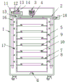
FIG. 1 is a schematic structural view of the present invention;
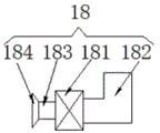
FIG. 2 is a schematic view of the structure of the dehumidifying device of the present invention;
fig. 3 is a schematic view of the box structure of the present invention.
In the figure: 1. a box body; 2. a support plate; 3. a servo motor; 4. a power shaft; 5. a support frame; 6. fixing the rod; 7. a connecting rod; 8. mounting holes; 9. inserting a rod; 10. placing a tray; 11. a heating box; 12. an electrical heating plate; 13. a blower; 14. an air outlet pipe; 15. a connecting pipe; 16. a conveying pipe; 17. a gas shower; 18. a moisture removal device; 181. a suction fan; 182. an exhaust pipe; 183. an air inlet pipe; 184. an air inlet pipe; 19. a control panel; 20. heat dissipation holes; 21. a box door; 22. and (4) an observation window.
Detailed Description
The technical solutions in the embodiments of the present invention will be described clearly and completely with reference to the accompanying drawings in the embodiments of the present invention, and it is obvious that the described embodiments are only some embodiments of the present invention, not all embodiments. Based on the embodiments in the present invention, all other embodiments obtained by a person skilled in the art without creative work belong to the protection scope of the present invention.
Referring to fig. 1-3, the present invention provides a technical solution: a high-efficiency drying device for tea processing comprises a box body 1, a supporting plate 2 is arranged on the upper portion of the inner wall of the box body 1, a servo motor 3 is arranged at the middle end of the top of the supporting plate 2, a power rotating shaft 4 is arranged at the bottom end of the servo motor 3, the bottom end of the power rotating shaft 4 penetrates through the supporting plate 2 to be rotatably connected with a supporting frame 5, a fixing rod 6 is arranged at the middle end of the bottom of the supporting frame 5, the bottom end of the fixing rod 6 is rotatably connected with the bottom of the inner wall of the box body 1 through a bearing, connecting rods 7 are uniformly and movably connected with the inner walls at two sides of the supporting frame 5, mounting holes 8 are uniformly arranged on the inner walls at two sides of the supporting frame 5, internal threads are arranged on the inner surfaces of the mounting holes 8, one end, close to the supporting frame, thereby changing the distance between the placing discs 10, the top of the end of the connecting rod 7 far away from the supporting frame 5 is provided with an inserting rod 9, the top of the inserting rod 9 is connected with the placing discs 10 through a slot so as to fix the placing discs 10 conveniently, the left side of the top of the supporting plate 2 is provided with a heating box 11, the inside of the heating box 11 is transversely provided with two groups of electric heating plates 12 with the same structure, the middle end of the top of the outer wall of the heating box 11 is provided with an air blower 13, the bottom of the air blower 13 is provided with an air outlet pipe 14, the bottom of the air outlet pipe 14 penetrates through the heating box 11, the middle end of the bottom of the heating box 11 is communicated and connected with a connecting pipe 15, the bottom of the connecting pipe 15 penetrates through the supporting plate 2, the connecting pipe 15 is arranged above the supporting frame 5, the two sides of the inner wall of the box 1 are both, so that the hot air can be uniformly sprayed, a moisture discharging device 18 is provided at the upper portion of the right side of the outer wall of the cabinet 1, and the moisture discharging device 18 is located below the support plate 2 for discharging moisture.
The dehumidifying device 18 comprises a suction fan 181 connected with the right side of the outer wall of the box body 1, an exhaust pipe 182 is connected with the right end of the suction fan 181, an air inlet pipe 183 is connected with the left end of the suction fan 181, the left end of the air inlet pipe 183 is communicated and connected with an air inlet pipe 184, and the air inlet pipe 184 is of a funnel-shaped structure, so that the moisture exhausting efficiency is improved;
a control panel 19 is arranged at the right end of the top of the front side of the box body 1, and the servo motor 3, the electric heating plate 12, the blower 13 and the suction fan 181 are respectively and electrically connected with the control panel 19;
the front side of the box body 1 is hinged with a box door 21 through a hinge, and the box door 21 is provided with an observation window 22;
circular heat dissipation holes 20 are uniformly formed in the middle end of the top of the front side of the box body 1, and filter screens are arranged on the surfaces of the heat dissipation holes 20, so that heat dissipation of the servo motor 3 and the blower 13 is facilitated, and dust is prevented from entering;
the rear side of box 1 evenly is provided with the hanging hole, and places the rear side of dish 10 and be provided with hanging hole assorted couple for hang and place dish 10, convenient to use.
The working principle is as follows: during the use, open chamber door 21, place the inside of placing dish 10 with tealeaves, fix through inserted bar 9 and place dish 10, close chamber door 21, start servo motor 3 through control panel 19, electric heating board 12, air-blower 13 and suction fan 181, servo motor 3 drives support frame 5 and rotates, thereby make and place dish 10 and rotate, thereby make and place the inside tealeaves rotation of dish 10, make tealeaves be heated evenly, and the air flow around the tealeaves accelerates, drying efficiency has been improved, air-blower 13 passes through gas shower nozzle 17 blowout with the heat that electric heating board produced, make hot-air spout evenly, thereby make tealeaves dry evenly, the moisture that produces among the drying process under the effect of suction fan 181, get into air-supply line 183 through intake pipe 184, thereby discharge through blast pipe 182.
Although embodiments of the present invention have been shown and described, it will be appreciated by those skilled in the art that changes, modifications, substitutions and alterations can be made in these embodiments without departing from the principles and spirit of the invention, the scope of which is defined in the appended claims and their equivalents.
Claims (6)
1. The utility model provides a tea processing uses high-efficient drying device, includes box (1), its characterized in that: the box body is characterized in that a supporting plate (2) is arranged on the upper portion of the inner wall of the box body (1), a servo motor (3) is arranged at the middle end of the top of the supporting plate (2), a power rotating shaft (4) is arranged at the bottom end of the servo motor (3), the bottom end of the power rotating shaft (4) penetrates through the supporting plate (2) and is rotatably connected with a supporting frame (5), a fixing rod (6) is arranged at the middle end of the bottom of the supporting frame (5), the bottom end of the fixing rod (6) is rotatably connected with the bottom of the inner wall of the box body (1) through a bearing, connecting rods (7) are uniformly and movably connected with the inner walls of the two sides of the supporting frame (5), mounting holes (8) are uniformly arranged on the inner walls of the two sides of the supporting frame (5), internal threads are arranged on the inner surface of the, and one end of the connecting rod (7) close to the support frame (5) is provided with an external thread matched with the internal thread, the top of one end of the connecting rod (7) far away from the support frame (5) is provided with an inserted rod (9), the top of the inserted rod (9) is connected with the placing disc (10) through a slot, the left side of the top of the support plate (2) is provided with a heating box (11), the inside of the heating box (11) is transversely provided with two groups of electric heating plates (12) with the same structure, the middle end of the top of the outer wall of the heating box (11) is provided with an air blower (13), the bottom of the air blower (13) is provided with an air outlet pipe (14), the bottom end of the air outlet pipe (14) penetrates through the heating box (11), the middle end of the bottom of the heating box (11) is communicated with a connecting pipe (15), the bottom of the connecting pipe (15), the box body is characterized in that transmission pipes (16) are arranged on two sides of the inner wall of the box body (1), the tops of the transmission pipes (16) are communicated and connected with a connecting pipe (15), gas spray heads (17) are uniformly arranged on one side, far away from the inner wall of the box body (1), of the transmission pipes (16), a dehumidifying device (18) is arranged on the upper portion of the right side of the outer wall of the box body (1), and the dehumidifying device (18) is located below the supporting plate (2).
2. The efficient drying device for tea processing according to claim 1, wherein: the dehumidifying device (18) comprises a suction fan (181) connected with the right side of the outer wall of the box body (1), the right end of the suction fan (181) is connected with an exhaust pipe (182), the left end of the suction fan (181) is connected with an air inlet pipe (183), the left end of the air inlet pipe (183) is communicated with an air inlet pipe (184), and the air inlet pipe (184) is of a funnel-shaped structure.
3. The efficient drying device for tea processing according to claim 2, wherein: the box is characterized in that a control panel (19) is arranged at the right end of the top of the front side of the box body (1), and the servo motor (3), the electric heating plate (12), the air blower (13) and the suction fan (181) are respectively electrically connected with the control panel (19).
4. The efficient drying device for tea processing according to claim 1, wherein: the front side of the box body (1) is hinged with a box door (21) through a hinge, and an observation window (22) is arranged on the box door (21).
5. The efficient drying device for tea processing according to claim 1, wherein: the box body (1) is characterized in that circular heat dissipation holes (20) are uniformly formed in the middle end of the top of the front side of the box body (1), and filter screens are arranged on the surfaces of the heat dissipation holes (20).
6. The efficient drying device for tea processing according to claim 1, wherein: the rear side of the box body (1) is uniformly provided with hanging holes, and the rear side of the placing plate (10) is provided with hooks matched with the hanging holes.
Priority Applications (1)
| Application Number | Priority Date | Filing Date | Title |
|---|---|---|---|
| CN202021006552.0U CN212987896U (en) | 2020-06-04 | 2020-06-04 | High-efficient drying device is used in tea processing |
Applications Claiming Priority (1)
| Application Number | Priority Date | Filing Date | Title |
|---|---|---|---|
| CN202021006552.0U CN212987896U (en) | 2020-06-04 | 2020-06-04 | High-efficient drying device is used in tea processing |
Publications (1)
| Publication Number | Publication Date |
|---|---|
| CN212987896U true CN212987896U (en) | 2021-04-16 |
Family
ID=75422517
Family Applications (1)
| Application Number | Title | Priority Date | Filing Date |
|---|---|---|---|
| CN202021006552.0U Expired - Fee Related CN212987896U (en) | 2020-06-04 | 2020-06-04 | High-efficient drying device is used in tea processing |
Country Status (1)
| Country | Link |
|---|---|
| CN (1) | CN212987896U (en) |
Cited By (2)
| Publication number | Priority date | Publication date | Assignee | Title |
|---|---|---|---|---|
| CN115486483A (en) * | 2022-09-01 | 2022-12-20 | 安徽省兰香缘农业生态发展有限责任公司 | Tea leaf drying equipment with uniform drying effect and uniform drying method thereof |
| CN115500528A (en) * | 2022-09-16 | 2022-12-23 | 湖南有吉食品有限公司 | Day lily food processing is with high-efficient equipment that cures |
-
2020
- 2020-06-04 CN CN202021006552.0U patent/CN212987896U/en not_active Expired - Fee Related
Cited By (2)
| Publication number | Priority date | Publication date | Assignee | Title |
|---|---|---|---|---|
| CN115486483A (en) * | 2022-09-01 | 2022-12-20 | 安徽省兰香缘农业生态发展有限责任公司 | Tea leaf drying equipment with uniform drying effect and uniform drying method thereof |
| CN115500528A (en) * | 2022-09-16 | 2022-12-23 | 湖南有吉食品有限公司 | Day lily food processing is with high-efficient equipment that cures |
Similar Documents
| Publication | Publication Date | Title |
|---|---|---|
| CN109610140A (en) | A kind of wardrobe with drying function | |
| CN110978644A (en) | Intelligent drying and shaping equipment and method for corrugated board | |
| CN208366006U (en) | A kind of filtering textile material chemical raw material post-processing drying unit | |
| CN210051084U (en) | Dehydrating unit is used in wig production and processing | |
| CN209371750U (en) | A kind of drying machine | |
| CN210486386U (en) | Secondary battery drying device | |
| CN210801788U (en) | Online drying device of plywood | |
| CN211424949U (en) | Chinese-medicinal material processing drying equipment | |
| CN222012581U (en) | Tobacco dryer | |
| CN210569681U (en) | Novel drum-type woollen blanket drying equipment | |
| CN113028787A (en) | Red pottery high efficiency energy saving drying device | |
| CN216011525U (en) | Food production drying-machine with disinfection function | |
| CN208139770U (en) | A kind of paper grade (stock) baker of good drying effect | |
| CN217031919U (en) | A kind of kiwi fruit pollen drying oven | |
| CN207662083U (en) | Electric drying oven with forced convection | |
| CN207280135U (en) | A kind of gypsum handcraft drying unit easy to pick and place | |
| CN211138334U (en) | Intelligent drying and shaping equipment for corrugated boards | |
| CN211177775U (en) | Chinese-medicinal material drying device | |
| CN212902521U (en) | Air supply device with filtering function of digital display air blowing drying box | |
| CN214120643U (en) | Dryer with dual drying mechanisms for bolt hot galvanizing | |
| CN211425001U (en) | Efficient drying and sterilizing box for non-woven fabrics | |
| CN211120281U (en) | A vacuum drying machine for chinese-medicinal material processing | |
| CN209825185U (en) | Regional energy-saving environment-friendly integrated curing barn | |
| CN210602479U (en) | A computer accessories drying device | |
| CN222275097U (en) | Efficient energy-saving pulp molding dryer |
Legal Events
| Date | Code | Title | Description |
|---|---|---|---|
| GR01 | Patent grant | ||
| GR01 | Patent grant | ||
| TR01 | Transfer of patent right | ||
| TR01 | Transfer of patent right |
Effective date of registration: 20211229 Address after: 465450 A5, building 4, back seat of administration center, Haiying East Road, Zishui street, Guangshan County, Xinyang City, Henan Province Patentee after: Henan Zhongkui Industrial Co.,Ltd. Address before: No. 129, Meilin Meiting village, Nanan City, Quanzhou City, Fujian Province, 362000 Patentee before: Huang Haibin |
|
| CF01 | Termination of patent right due to non-payment of annual fee | ||
| CF01 | Termination of patent right due to non-payment of annual fee |
Granted publication date: 20210416 |