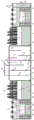
Integrated villages and towns sewage treatment system
Technical Field
The utility model belongs to the technical field of sewage treatment, concretely relates to integration villages and small towns sewage treatment system.
Background
In recent years, rural economy in China is rapidly developed, the rural living standard is remarkably improved, but the improvement of the living environment of vast rural areas does not achieve ideal results. Because the environment protection awareness of residents in rural areas is generally thin, environment protection facilities are incomplete, the management is not in place and the like, most villages and towns do not have perfect sewage collection systems, and untreated domestic sewage in vast village and town areas is discharged randomly; untreated domestic sewage is discharged at will, so that the water quality of ditches and ponds blackens and becomes smelly, mosquitoes breed, the rural living environment is affected, and the physical health of residents is threatened. The rural domestic sewage is mainly from toilet flushing water, kitchen washing water, washing machine drainage, washing drainage and other drainage of peasants. The sewage quality has larger variation range along with the sewage source, whether the toilet is flushed or not, time interval characteristics and the like. Therefore, although the rural economy of China develops rapidly, the rural sewage treatment rate is very low, and the problem of rural water environment pollution is not optimistic.
Aiming at the treatment of sewage in villages and towns, the research of foreign scholars mainly focuses on: (1) the high-efficiency algae pond is provided and developed on the basis of the stable pond to treat pollutants, but the technology is obviously influenced by environmental factors such as temperature, climate and the like, when the temperature is too high or low, the growth of algae is inhibited to influence the treatment effect, and the water body characteristics, humus, algae and non-biological suspended matters influence the absorption of the algae to light and influence the treatment effect; (2) the new technology of efficient and continuous sewage irrigation of 'FILTER' is utilized to obtain better sewage treatment effect, but the cost of a hidden pipe drainage system is higher, so that the treatment method is influenced by the growing season of crops and the underground water level; (3) the sewage treatment method adopts a biomembrane method, a plankton method and a method combining physical, chemical and biological measures to achieve good effect, but has higher requirements on process conditions, needs professional personnel to operate and maintain, and is not suitable for the actual conditions of villages and towns in China; (4) the wetland sewage treatment system ensures that pollutants in the sewage are filtered by the wetland, absorbed by soil or converted into harmless substances by microorganisms, and has the defects of large occupied area and influence by oxygen supply, air temperature and plant growth season; (5) the distributed urban infrastructure system adopts an advanced membrane bioreactor built in a remote village without a drainage pipe network, simultaneously develops the research of sewage treatment of the undercurrent type artificial wetland, and purifies sewage by utilizing the interception action of microorganisms growing on the surface of the filler, plant roots, surface soil and the filler.
The research on the sewage of villages and towns in China starts late, the sewage treatment facility of the villages and the towns is still in the development stage, and the construction and the operation management are relatively lagged. The existing village and town domestic sewage treatment method mainly adopts processes of septic tanks, constructed wetlands, anaerobic ponds, land infiltration and the like without power or micro-power consumption. In addition, the method also comprises a rapid land infiltration method, a biological contact oxidation method, a nitrogen and phosphorus removal activated sludge method, a membrane bioreactor and the like. However, the method has certain limitations, and generally has the problems of complicated capital construction, large engineering quantity, large occupied area, low economic benefit, poor treatment effect, high requirements on process conditions and the like. And the sewage collection in rural areas is difficult, the investment of pipe networks is large, and the level of operation management personnel is not high, so the technology can not completely meet the treatment requirement of the domestic sewage of dispersive villages and towns.
Disclosure of Invention
Based on prior art's not enough, the utility model aims to provide a practice thrift area of taking up an area of and investment cost's integrated villages and small towns sewage treatment system, the management of being convenient for, and add the view effect.
In order to achieve the above purpose, the utility model adopts the following technical scheme:
an integrated village and town sewage treatment system comprises a rectangular pool body, wherein a closed box body is arranged at the center of the pool body, and the box body is higher than the pool body; a first partition plate and a second partition plate are sequentially arranged in the box body from left to right, the first partition plate and the second partition plate are both in seamless connection with the inner wall of the box body, the box body is divided into an aerobic treatment chamber, an anoxic treatment chamber and a baffling anaerobic chamber from left to right by the first partition plate and the second partition plate, and a baffle plate is arranged in the baffling anaerobic chamber; a water inlet pipe is inserted into the top of the anaerobic treatment chamber, and the lower end of the water inlet pipe extends into the lower part of the anaerobic treatment chamber; a main water delivery pipe is inserted into the top of the aerobic treatment chamber, the lower end of the main water delivery pipe extends into the lower part of the aerobic treatment chamber, the upper end of the main water delivery pipe extends out of the aerobic treatment chamber, water delivery branch pipes are inserted into the right part of the anoxic treatment chamber and the left part of the baffling anaerobic chamber, the lower ends of the water delivery branch pipes extend into the upper part of the box body, the upper ends of the two water delivery branch pipes extend out of the box body and are communicated with the main water delivery pipe, sewage in the anoxic treatment chamber and the baffling anaerobic chamber enters the aerobic treatment chamber through the water delivery branch pipes and the main water delivery pipe, and a water pump and an ejector are sequentially installed on the main water delivery pipe along the sewage flowing direction; the upper part of the first clapboard is provided with a backflow port, the lower part of the second clapboard is provided with a water through port, and the right side wall of the box body is provided with a water outlet;
the front, the back and the right of the box body are respectively provided with a third clapboard, the left of the box body is provided with a fourth clapboard, the third clapboard and the fourth clapboard are sequentially connected and enclosed to form a rectangular frame body, the bottoms of the third clapboard and the fourth clapboard are both fixed at the bottom of the tank body, the top of the third clapboard is level with the upper port of the tank body, and the height of the fourth clapboard is lower than that of the third clapboard; the part of the pool body, which is positioned outside the box body, is divided into a surface flow treatment chamber and a horizontal undercurrent treatment chamber by a frame body from inside to outside, a first packing layer and a second packing layer are sequentially paved in the surface flow treatment chamber from bottom to top, a matrix packing layer and a soil covering layer paved on the surface of the matrix packing layer are arranged in the horizontal undercurrent treatment chamber, a water outlet channel is arranged on the right side of the horizontal undercurrent treatment chamber, and the upper port of the water outlet channel is not lower than the upper surface of the soil covering layer; the bottom of the right side wall of the horizontal undercurrent treatment chamber is provided with a water outlet pipe, the water outlet pipe extends into the upper part of the water outlet channel, the upper port of the water outlet pipe is lower than the fourth partition plate, and the middle part of the right side wall of the water outlet channel is provided with a water outlet pipe.
Preferably, the left side and the right side of the box body are both provided with a limiting strip along the front-back direction.
Preferably, the number of the baffle plates in the baffle anaerobic chamber is two, the two baffle plates are arranged in a left and right mode, the bottom of the baffle plate positioned on the left side is fixed on the bottom surface of the box body, the top of the baffle plate positioned on the right side is fixed on the top of the box body, and the front side and the rear side of each baffle plate are respectively connected with the front side wall and the rear side wall of the box body in a seamless mode.
Preferably, the first packing layer is laid by cobblestones, and the second packing layer is laid by coarse sand.
Furthermore, emergent aquatic plants are planted on the second filler layer.
Preferably, the matrix packing layer comprises a third packing layer, a fourth packing layer and a fifth packing layer which are sequentially arranged from inside to outside, the third packing layer and the fifth packing layer are paved by gravels, the fourth packing layer is composed of a zeolite layer and a shale ceramsite layer, and the zeolite layer is positioned below the shale ceramsite layer.
Furthermore, the covering soil layer is planted with the hygrophytes.
Preferably, the outlet channel is provided with a cover plate for closing the upper port of the outlet channel.
The device has simple and reasonable structure, and has the advantages of land occupation saving, low energy consumption, high effluent quality and the like; the box body is provided with the combination of a water pump and an ejector, so that various functions of sewage backflow, aeration and oxygenation, hydraulic stirring and the like are realized, continuous circulation of anoxic-anaerobic-aerobic on a spatial sequence is realized, and the treatment efficiency is high; the water treated by the box body flows automatically into the surface flow treatment chamber after falling aeration oxygenation, and then enters the horizontal undercurrent treatment chamber after passing through the surface flow treatment chamber, so that pollution factors such as COD, nitrogen, phosphorus and the like in the water body are further removed, and the advanced treatment of the sewage is realized; in addition, the system has low requirements on site conditions and automation, and is suitable for village and town areas lacking of professional managers.
Drawings
Fig. 1 is a schematic structural diagram of the present invention;
fig. 2 is a top view of fig. 1.
Detailed Description
As shown in fig. 1 and 2 (the direction indicated by the arrow in the figure is the direction of water flow in the system), an integrated village and town sewage treatment system comprises a rectangular tank body 1, a closed part 3 is arranged at the center of the tank body 1, the tank body 2 is higher than the tank body 1, and the left side and the right side of the tank body 2 are respectively provided with a limit strip along the front-back direction. Be equipped with first baffle 7 and second baffle 8 from a left side to the right side in proper order in the box 2, both ends and upper and lower both ends respectively with box 2 preceding lateral wall, back lateral wall, top and bottom seamless connection around first baffle 7, both ends and upper and lower both ends respectively with box 2 preceding lateral wall, back lateral wall, top and bottom seamless connection around second baffle 8, aerobic treatment room 27, oxygen deficiency treatment room 28, baffling anaerobic room 29 are separated into with box 2 from a left side to the right side to first baffle 7 and second baffle 8. Two baffle plates 9 are arranged in the baffling anaerobic chamber 29, the two baffle plates 9 are arranged on the left and right sides, the bottom of the baffle plate 9 on the left side is fixed on the bottom surface of the box body 2, the top of the baffle plate 9 on the right side is fixed on the top of the box body 2, the front side and the rear side of the baffle plate 9 are respectively connected with the front side wall and the rear side wall of the box body 2 in a seamless mode, and the length of the baffle plate 9 in the vertical direction is larger than 1/2 of the height of the baffl. The top of the anoxic treatment chamber 28 is inserted with a water inlet pipe 10, and the lower end of the water inlet pipe 10 extends into the lower part of the anoxic treatment chamber 28. The top of the aerobic treatment chamber 27 is inserted with a main water pipe 12, the lower end of the main water pipe 12 extends into the lower part of the aerobic treatment chamber 27, and the upper end of the main water pipe 12 extends out of the aerobic treatment chamber 27; the water delivery branch pipes 11 are inserted into the right part of the anoxic treatment chamber 28 and the left part of the baffling anaerobic chamber 29, the lower ends of the water delivery branch pipes 11 extend into the upper part of the box body 2, and the upper ends of the two water delivery branch pipes 11 extend out of the box body 2 and are communicated with the main water delivery pipe 12; the sewage in the anoxic treatment chamber 28 and the baffling anaerobic chamber 29 enters the aerobic treatment chamber 27 through the water delivery branch pipe 11 and the water delivery main pipe 12, and the water pump 13 and the ejector 14 are sequentially installed on the water delivery main pipe 12 along the sewage flow direction. The upper part of the first clapboard 7 is provided with a return port 15, the lower part of the second clapboard 8 is provided with a water through port 16, and the right side wall of the box body 2 is provided with a water outlet 17.
The preceding, back, the right-hand third baffle 5 that all is provided with of box 2, and the left of box 2 is provided with fourth baffle 4, third baffle 5 and fourth baffle 4 connect gradually, enclose the framework that closes formation rectangle, the bottom of third baffle 5 and fourth baffle 4 all is fixed in the bottom of cell body 1, the top of third baffle 5 and the last port looks parallel and level of cell body 1, and the height of fourth baffle 4 is less than third baffle 5. The part of the pool body 1 positioned outside the box body 2 is divided into a surface flow treatment chamber 30 and a horizontal undercurrent treatment chamber 31 from inside to outside by a frame body. A first packing layer 20 and a second packing layer 21 are sequentially paved in the surface flow treatment chamber 30 from bottom to top, the upper surface of the second packing layer 21 is lower than the fourth partition plate 4, and cattail 18 is planted on the second packing layer 21. A matrix filler layer and a covering soil layer 26 paved on the surface of the matrix filler layer are arranged in the horizontal undercurrent treatment chamber 31, the upper surface of the covering soil layer 26 is lower than the fourth clapboard 4, and canna 19 is planted on the covering soil layer 26. An outlet channel 32 is arranged on the right side of the horizontal subsurface flow treatment chamber 31, the upper end opening of the outlet channel 32 is not lower than the upper surface of the covering soil layer 26, and a cover plate 34 for closing the upper end opening of the outlet channel 32 is arranged on the outlet channel 32. The bottom of the right side wall of the horizontal undercurrent treatment chamber 31 is provided with a water outlet pipe 6, the water outlet pipe 6 extends into the upper part of the water outlet channel 32, the upper port of the water outlet pipe 6 is flush with the upper surface of the soil covering layer 26, and the middle part of the right side wall of the water outlet channel 32 is provided with a water outlet pipe 33.
The first packing layer 20 is formed by laying cobblestones, the second packing layer 21 is formed by laying coarse sand, the matrix packing layer comprises a third packing layer 22, a fourth packing layer and a fifth packing layer 24 which are sequentially arranged from inside to outside, the third packing layer 22 and the fifth packing layer 24 are formed by laying the cobblestones, the fourth packing layer is formed by a zeolite layer 23 and a shale ceramsite layer 25, and the zeolite layer 23 is positioned below the shale ceramsite layer 25.
The utility model discloses during the use, sewage (in advance through the sediment, filter) gets into oxygen deficiency treatment chamber 28 through oral siphon 10, carry out COD degradation and denitrification in oxygen deficiency treatment chamber 28, then through 16 entering baffling anaerobic chamber 29 of discharge port, further COD degradation and anaerobism phosphorus release in baffling anaerobic chamber 29, water pump 13 siphons away oxygen deficiency treatment chamber 28 and baffling anaerobic chamber 29's sewage, get into aerobic treatment chamber 27 through ejector 14, turn into nitrate nitrogen through the ammonia nitrogen of nitrification in with sewage, the nitrifying liquid that is rich in nitrate nitrogen flows back to oxygen deficiency treatment chamber 28 through return opening 15, thereby realize oxygen deficiency-anaerobism-aerobic continuous circulation, reach nitrogen and phosphorus removal, reduce the purpose of COD. The sewage treated by the box body 2 falls into the right part of the surface flow treatment chamber 30 through the water outlet 17, then flows to the left part of the surface flow treatment chamber 30 from the front and the back sides of the box body 2 respectively, is adsorbed and purified by the first packing layer 20 and the second packing layer 21, overflows to the left part of the horizontal undercurrent treatment chamber 31 through the fourth partition plate 4, then flows to the right part of the horizontal undercurrent treatment chamber 31 from the front and the back sides of the frame body respectively, enters the water outlet channel 32 through the water outlet pipe 6 under the action of the adsorption and purification of the matrix packing layer, microorganisms and plants, and finally is discharged from the water outlet pipe 33.
The present invention is not limited by the above embodiments, and the description in the above embodiments and the description is only for illustrating the principle of the present invention, and the present invention will have various changes and improvements without departing from the spirit and scope of the present invention, and these changes and improvements all fall into the scope of the claimed invention.