SUMMERY OF THE UTILITY MODEL
The utility model provides a not enough to prior art, the utility model provides a die assembly who uses on the powder forming press of crank link mechanism can change the product at the ascending size of vertical side to satisfy the production demand.
In order to achieve the above purpose, the utility model provides a following technical scheme: the utility model provides a die assembly for powder forming press, is including removing pressure seat and moulding-die base, removes to press the seat to be located the top of moulding-die base, is provided with the guide pillar on the moulding-die base, remove to press seat and guide pillar sliding connection, remove to press and be provided with crank link mechanism between seat and the moulding-die base, remove to press and be provided with the pneumatic cylinder on the seat, be provided with the hydraulic spindle on the pneumatic cylinder, the hydraulic spindle is vertical to be passed and removes to press the seat, is provided with the module on the hydraulic spindle, be provided with down the module on the moulding-die base, the module is located under the module down.
Further, a spring prepressing mechanism is arranged between the upper module and the hydraulic spindle and comprises a stabilizing plate and a prepressing spring, two ends of the prepressing spring are respectively connected with the stabilizing plate and the hydraulic spindle, a limiting sleeve is arranged on the stabilizing plate and is located in the limiting sleeve, the end of the hydraulic spindle extends into the limiting sleeve, one part of the end of the hydraulic spindle extends into the prepressing spring, a limiting protrusion extending inwards is arranged at one end, far away from the stabilizing plate, of the limiting sleeve, and a limit is arranged below the corresponding limiting protrusion at the end of the hydraulic spindle.
Furthermore, a guide rod is arranged between the stabilizing plate and the fixed pressing seat, the guide rod penetrates through the stabilizing plate, and the stabilizing plate is connected with the guide rod in a sliding mode.
Further, the pressing die base is provided with a supporting block, the supporting block is provided with a supporting groove, the lower die block is located in the supporting groove, a mandril is arranged in the supporting groove and vertically and slidably connected with the supporting groove, the mandril penetrates through the lower die block and vertically and slidably connected with the lower die block, the pressing die base is provided with an air cylinder, and the mandril is connected with a piston rod of the air cylinder
Furthermore, a telescopic cover is arranged between the movable pressing seat and the stabilizing plate, and the limiting sleeve and the part of the hydraulic spindle extending out of the movable pressing seat are both positioned in the telescopic cover.
Furthermore, a compression spring is arranged on the guide post, and two ends of the compression spring are respectively connected with the movable pressing seat and the pressing die base.
Further, the crank-link mechanism comprises a connecting rod and a crank, one end of the connecting rod is rotatably connected with the movable pressing seat, the other end of the connecting rod is rotatably connected with one end of the crank, the other end of the crank is connected with a driving motor, a speed reducer is arranged between the crank and the driving motor, and the driving motor and the speed reducer are located on an inner ring of the pressing die base.
Compared with the prior art, the beneficial effects of the utility model are that: crank link mechanism makes the removal press the seat reciprocating motion from top to bottom on the guide pillar, drives and goes up the mould head and press on the lower mould head, suppresses the powder, when the size of product changes, can adjust the position of hydraulic spindle in vertical side through the pneumatic cylinder to the suppression distance between module and the lower module in the adjustment satisfies the suppression to the product of size difference, reduces the quantity and the change number of times of last mould head, need not also bed hedgehopping lower module, improves product suppression precision.
Detailed Description
In the description of the present invention, it should be noted that, for the orientation words, such as the terms "center", "lateral (X)", "longitudinal (Y)", "vertical (Z)", "length", "width", "thickness", "upper", "lower", "front", "rear", "left", "right", "vertical", "horizontal", "top", "bottom", "inner", "outer", "clockwise", "counterclockwise", etc., the orientation and the positional relationship are indicated based on the orientation or the positional relationship shown in the drawings, and the description is only for convenience of describing the present invention and simplifying the description, but not for indicating or implying that the device or the element referred to must have a specific orientation, be constructed and operated in a specific orientation, and should not be construed as limiting the specific protection scope of the present invention.
Furthermore, if the terms "first" and "second" are used for descriptive purposes only, they are not to be construed as indicating or implying relative importance or implicitly indicating the number of technical features. Thus, the definition of "a first" or "a second" feature may explicitly or implicitly include one or more of the features, and "a plurality" or "a plurality" in the description of the invention means two or more unless a specific definition is explicitly provided.
The present invention is further explained with reference to fig. 1 to 3.
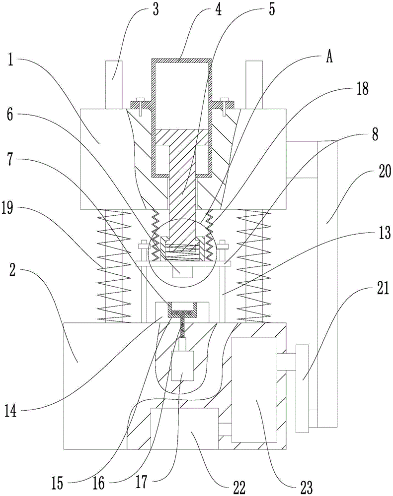
The utility model provides a die assembly for powder forming press, is including removing pressure seat 1 and moulding-die base 2, removes the top that the pressure seat 1 is located moulding-die base 2, is provided with guide pillar 3 on moulding-die base 2, remove and press seat 1 and guide pillar 3 sliding connection, remove and be provided with crank link mechanism between pressure seat 1 and the moulding-die base 2, remove and be provided with pneumatic cylinder 4 on pressing seat 1, be provided with hydraulic spindle 5 on the pneumatic cylinder 4, hydraulic spindle 5 vertically passes and removes pressure seat 1, is provided with module 6 on the hydraulic spindle 5, be provided with down module 7 on moulding-die base 2, module 7 is located under module 6 down.
Preferably, the supporting block 14 is provided with a feeding mechanism, and the feeding mechanism puts the powder to be processed into the lower module 7 before the upper module 6 is pressed down.
As shown in fig. 1 and 3, when enough powder exists in the lower module 7, the crank-link mechanism drives the movable pressing seat 1 to press downwards, the powder is pressed after the upper module 6 contacts the powder, the movable pressing seat 1 is driven to ascend by the crank-link mechanism after pressing, product press forming is completed, when the size of a product to be pressed is changed, the position of the hydraulic spindle 5 in the vertical direction is changed through the hydraulic cylinder 4, namely the initial position of the upper module 6 on the movable pressing seat 1 is changed, the pressing distance of the upper die to the product is changed, the size of the product in the vertical direction is changed according to production requirements, pressing of products with different sizes is met, the number of the upper die and the replacement times are reduced, the lower module 7 does not need to be lifted, and the product pressing precision is improved.
As shown in fig. 1 and fig. 2, in this embodiment, preferably, a spring pre-pressing mechanism is disposed between the upper module 6 and the hydraulic spindle 5, the spring pre-pressing mechanism includes a stable plate 8 and a pre-pressing spring 9, two ends of the pre-pressing spring 9 are respectively connected to the stable plate 8 and the hydraulic spindle 5, a position-limiting sleeve 10 is disposed on the stable plate 8, the pre-pressing spring 9 is located in the position-limiting sleeve 10, an end portion of the hydraulic spindle 5 extends into the position-limiting sleeve 10, a portion of an end portion of the hydraulic spindle 5 extends into the pre-pressing spring 9, an inward extending position-limiting protrusion 11 is disposed at one end of the position-limiting sleeve 10, which is far away from the stable plate 8, the position-limiting protrusion 11 abuts against the hydraulic spindle 5 and is slidably connected with the hydraulic spindle 5, so that the position-limiting sleeve 10 can vertically move on the hydraulic spindle 5, a position-limiting ring 12 is disposed below the position-limiting protrusion 11 at the, when the limiting sleeve 10 reaches the maximum descending distance, which is the initial state of the limiting sleeve 10, a certain distance is left between the hydraulic main shaft 5 and the stabilizing plate 8.
When the movable press seat 1 drives the hydraulic cylinder 4 and the hydraulic main shaft 5 to descend, the upper module 6 contacts the powder. At the moment, the pre-pressing spring 9 is in an extension state, the bottom end face of the hydraulic spindle 5 is not in contact with the extrusion stabilizing plate 8, the upper module 6 can pre-press the powder through the pre-pressing spring 9, the pre-pressing spring 9 is compressed along with the gradual descending of the moving pressing seat 1, the pre-pressing force of the upper module 6 on the powder is gradually increased, the pre-pressing force on the powder is enabled to be increased gradually until the hydraulic spindle 5 abuts against the stabilizing plate 8, the pre-pressing is completed, namely the hydraulic spindle 5 is driven by the crank-link mechanism to carry out final press forming on the powder, after the powder is formed, the crank-link mechanism drives the hydraulic spindle 5 to ascend and retreat from the stabilizing plate 8, the pre-pressing spring 9 is gradually extended, the upper module 6 is enabled to be pressed on the product until the limiting ring 12 contacts with the limiting protrusion 11, the limiting sleeve 10 is pulled up.
Preferably, go up module 6 and stabilizer plate 8 between for can dismantle the connection, conveniently change the last module 6 of different models in order to adapt to different product models.
As shown in fig. 1, a guide rod 13 is preferably disposed between the stabilizing plate 8 and the fixed pressing base, the guide rod 13 penetrates through the stabilizing plate 8, the stabilizing plate 8 is slidably connected with the guide rod 13, the guide rod 13 guides the stabilizing plate 8 and prevents the stabilizing plate 8 from rotating axially during the up-and-down movement, which results in that the upper die block 6 cannot be aligned with the lower die block 7 during the pressing down, thereby affecting the powder forming.
As shown in fig. 1, in the preferred embodiment, a supporting block 14 is arranged on the die base 2, a supporting groove 15 is arranged on the supporting block 14, the lower die block 7 is located in the supporting groove 15, an ejector rod 16 is arranged in the supporting groove 15, the ejector rod 16 is vertically and slidably connected with the supporting groove 15, the ejector rod 16 penetrates through the lower die block 7 and is vertically and slidably connected with the lower die block 7, an air cylinder 17 is arranged on the die base 2, the ejector rod 16 is connected with a piston rod of the air cylinder 17, the supporting groove 15 is detachably connected with the lower die block 7, the lower die blocks 7 of different models can be conveniently replaced to adapt to different product models, and the air cylinder 17 operates after the product is formed to enable the ejector rod 16 to eject the product out of the lower die block 7.
Preferably, the top of the ejector rod 16 is provided with a top plate extending outwards, the top plate increases the contact area between the ejector rod 16 and the product when ejecting the product, and reduces the damage to the product when the ejector rod 16 ejects the product.
As shown in fig. 1, a telescopic cover 18 is preferably disposed between the movable pressure seat 1 and the stabilizing plate 8, the stop collar 10 and the part of the hydraulic spindle 5 extending out of the movable pressure seat 1 are both located in the telescopic cover 18, and the telescopic cover 18 prevents powder or dust in air from adhering to the hydraulic spindle 5, thereby ensuring the moving precision of the hydraulic spindle 5.
As shown in fig. 1, a compression spring 19 is disposed on the guide post 3 in the preferred embodiment, two ends of the compression spring 19 are respectively connected to the movable pressing base 1 and the pressing base 2, and since the crank link mechanism is located on one side of the movable pressing base 1, stress on two opposite sides of the movable pressing base 1 is not uniform, the compression spring 19 can provide a certain supporting elastic force for the movable pressing base 1, so as to ensure that stress on two sides of the movable pressing base 1 is gentle, thereby helping the movable pressing base 1 to rise and fall better.
As shown in fig. 1 and 3, the crank-link mechanism of the present embodiment preferably includes a connecting rod 20 and a crank 21, one end of the connecting rod 20 is rotatably connected to the movable pressing base 1, the other end of the connecting rod is rotatably connected to one end of the crank 21, the other end of the crank 21 is connected to a driving motor 22, a reducer 23 is disposed between the crank 21 and the driving motor 22, the driving motor 22 and the reducer 23 are disposed in the die base 2, the guide post 3 limits the movable pressing base 1 to move only up and down, the rotation of the main shaft of the driving motor 22 is changed into the up and down movement of the movable base through the crank 21 and the connecting rod 20, and the driving motor 22 reduces the rotation speed of the crank 21 through the reducer 23 to increase the torque of the crank 21, so that the connecting rod 20 can drive. When the crank 21 rotates to make the connection between the crank 21 and the connecting rod 20 approach the lowest position or just leave the lowest position, the moving speed of the moving base is low, i.e. the upper module 6 approaches and leaves smoothly, which is beneficial to the molding of powder.
In order to improve the precision of a product, the matching precision between the upper module 6 and the lower module 7 is high, a relatively closed area is formed between the upper module 6 and the lower module 7 during powder pressing, if the upper template descends too fast during pressing, a high-pressure area is formed between the upper module 6 and the lower module 7 instantly, internal high-pressure air is sprayed out from the high-pressure area to carry out a plurality of fine powder, the powder used for pressing is reduced, and the final quality of the product is influenced, the descending speed of the movable pressing seat 1 is slowed down after the movable pressing seat 1 just contacts the powder, the formation of the high-pressure area is prevented, the air between the powder can be discharged smoothly, the quantity of the powder carried out by the air is reduced, and the final quality of the product is improved; after the powder is pressed, the movable pressing seat 1 rises at a slower speed to enable the upper module 6 to leave the product, if the upper module 6 quickly leaves the product which is just formed, a negative pressure area is generated between the upper module 6 and the lower module 7, and the outside air can quickly enter the negative pressure area, impact is caused on the formed product, the structure of the product is damaged, and the quality of the product is influenced.
It is above only the utility model discloses a preferred embodiment, the utility model discloses a scope of protection does not only confine above-mentioned embodiment, the all belongs to the utility model discloses a technical scheme under the thinking all belongs to the utility model discloses a scope of protection. It should be noted that, for those skilled in the art, various modifications and decorations can be made without departing from the principle of the present invention, and these modifications and decorations should also be regarded as the protection scope of the present invention.