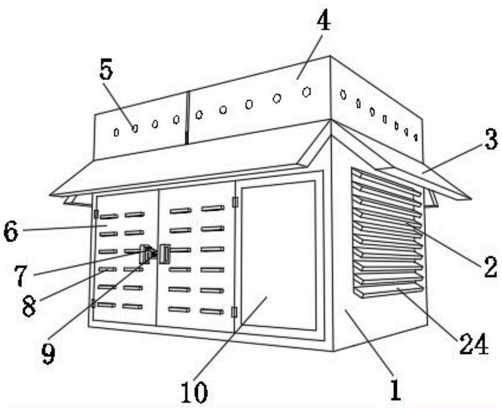
Outdoor rain-proof snow distribution cabinet
Technical Field
The utility model relates to a switch board technical field especially relates to an outdoor rain-proof snow distribution cabinet.
Background
The distribution box is characterized in that a switch device, a measuring instrument, a protective electrical appliance and auxiliary equipment are assembled in a closed or semi-closed metal cabinet or on a screen according to the requirement of electrical wiring to form a low-voltage distribution device, a circuit can be switched on or off by a manual or automatic switch in normal operation, the circuit is switched off or an alarm is given by the protective electrical appliance in fault or abnormal operation, various parameters in operation can be displayed by the measuring instrument, certain electrical parameters can be adjusted, and the deviation from the normal working state is prompted or signaled.
Through the retrieval, chinese patent application number is CN 209461837U's patent, discloses an outdoor rain-proof snow distribution cabinet, including the water catch bowl, its characterized in that, the lateral wall of water catch bowl is provided with the wash port, the telescoping device is installed to the lower extreme of water catch bowl, the baffle is installed to the lower extreme of wash port, the below of telescoping device is provided with distribution cabinet main part, but above-mentioned technical scheme is owing to need the manual work just can carry out the lifting to the lifter plate through rotating the rocker, consequently still has the problem that can't in time clear away the snow on the switch board.
SUMMERY OF THE UTILITY MODEL
The utility model aims at solving the defects existing in the prior art and providing an outdoor rain and snow prevention distribution cabinet.
In order to achieve the above purpose, the utility model adopts the following technical scheme:
an outdoor rain and snow prevention distribution cabinet comprises a protective shell, wherein four baffles are arranged on the outer wall of the protective shell respectively, the four baffles form thirty-degree included angles with the outer wall of the protective shell respectively, a water collecting tank is arranged on the outer wall of the top of the protective shell, more than three drain holes are formed in the outer wall of the water collecting tank respectively, two T-shaped chutes are formed in the outer walls of the two sides of the water collecting tank respectively, two T-shaped sealing blocks are arranged on the inner walls of the two T-shaped chutes respectively, a movable plate is arranged on the inner wall of the water collecting tank, more than three semicircular bulges are arranged on the outer wall of the top of the movable plate respectively, heating wires are arranged on the inner walls of the semicircular bulges, two support columns are arranged on the outer wall of the bottom of the movable plate respectively, a rectangular groove is, two sealed piece bottom outer walls of T type are provided with two elastic bands respectively, two elastic band bottom outer walls set up respectively on the top outer wall of protective housing, rectangle recess top outer wall is provided with two bearer bars respectively, bearer bar top outer wall is opened there is the through-hole, the support column runs through bearer bar top outer wall through the through-hole, the welding of support column outer wall has the spring, spring bottom outer wall sets up on the bottom inner wall of bearer bar, the length of support column bottom outer wall apart from bearer bar bottom inner wall equals half of spring length, bearer bar bottom inner wall is provided with the heating wire switch, heating wire switch and heating wire electric connection.
As a further aspect of the present invention: the outer wall of one side of the protective shell is respectively fixed with two cabinet doors through hinges, the outer walls of the two cabinet doors are respectively provided with more than three heat dissipation holes, the outer walls of the heat dissipation holes are provided with rectangular shielding covers, the outer walls of two sides of the protective shell are respectively provided with two heat dissipation windows, and the inner walls of the heat dissipation windows are respectively rotatably connected with more than three heat insulation boards through damping rotating shafts.
As a further aspect of the present invention: the outer wall of the cabinet door is provided with a key hole, and the outer wall of the key hole is provided with a protective cover.
As a further aspect of the present invention: the protective housing inner wall is provided with temperature sensor and control panel respectively, and protective housing top inner wall is provided with two radiator fan respectively, radiator fan and temperature sensor and control panel electric connection.
As a further aspect of the present invention: two drying boxes are respectively arranged on the inner wall of one side of the protective shell.
As a further aspect of the present invention: an observation window is arranged on the outer wall of one side of the protective shell, and the observation window is made of toughened glass.
As a further aspect of the present invention: the protective shell, the baffle, the water collecting tank and the movable plate are made of stainless steel.
The utility model has the advantages that:
1. by arranging the movable plate, the semicircular bulge internally provided with the heating wire, the support column, the spring and the heating wire switch, when snowing weather is met, snow can be accumulated on the movable plate, when certain weight is accumulated, the movable plate can downwards extrude the spring through the T-shaped slide rail, the support column continuously downwards moves along with the continuous rising of the weight of the accumulated snow, when the support column moves to a certain distance, the support column can extrude the heating wire switch to be opened to carry out power-on heating on the heating wire in the semicircular bulge, the semicircular bulge can improve the contact area between the outer wall at the top of the movable plate and the accumulated snow, so that the snow can be rapidly melted, the accumulated snow in the water collecting tank is discharged from the water discharging hole after being changed into snow water, the weight of the accumulated snow on the water collecting tank is reduced, at the moment, the support column upwards moves through the elasticity of the spring, the workload of workers is reduced, meanwhile, the heating wires are not required to be electrified for heating all the time, and the electric energy consumption is saved.
2. By arranging the T-shaped sealing block and the elastic belt, the problem that rainwater flows into the bottom of the movable plate through a gap in the T-shaped sliding groove to damage electronic components at the bottom can be avoided, and the overall sealing performance of the power distribution cabinet is improved; through setting up the louvre, the heated board that heat dissipation window and damping pivot are connected, when weather is hot, rotate the heated board through the damping pivot, let heated board and heat dissipation window outer wall be certain contained angle, let the quick heat effluvium with the inside production of switch board of heat dissipation window cooperation louvre, when the weather is cold, can rotate the heated board to the angle parallel with the heat dissipation window through the damping pivot, let the heat dissipation window sealed by the heated board to fine heat preservation effect has been played.
3. Through the arrangement of the temperature sensor and the cooling fan, the temperature sensor can transmit the temperature inside the power distribution cabinet to the control panel in real time, when the temperature exceeds the set temperature, the control panel can control the cooling fan to rotate, so that hot air inside the power distribution cabinet is rapidly discharged, and when the temperature drops below the set temperature, the control panel can control the cooling fan to stop rotating, so that the waste of electric energy is avoided; through setting up the visor, can effectually protect the key hole not receive external environment erosion, avoid the key hole to expose the problem that easily damages outside for a long time.
Drawings
Fig. 1 is a schematic view of a main view structure of an outdoor rain and snow prevention power distribution cabinet provided by the utility model;
fig. 2 is a schematic top view structure diagram of an outdoor rain and snow prevention power distribution cabinet provided by the utility model;
fig. 3 is a schematic structural view of a movable plate of the outdoor rain and snow prevention distribution box cabinet provided by the utility model;
fig. 4 is a schematic structural view of a protective frame of an outdoor rain and snow prevention power distribution cabinet provided by the utility model;
fig. 5 is a schematic view of an internal structure of a protective shell of the outdoor rain and snow prevention distribution box cabinet provided by the utility model;
fig. 6 is the utility model provides a circuit flow schematic diagram of outdoor rain-proof snow distribution cabinet.
In the figure: 1-protective shell, 2-heat dissipation window, 3-baffle, 4-water collection tank, 5-water discharge hole, 6-cabinet door, 7-protective cover, 8-heat dissipation hole, 9-key hole, 10-observation window, 11-movable plate, 12-semicircular bulge, 13-T type sliding groove, 14-elastic band, 15-support column, 16-protection frame, 17-electric heating wire switch, 18-spring, 19-temperature sensor, 20-control panel, 21-heat dissipation fan, 22-drying box, 23-T type sealing block and 24-heat insulation plate.
Detailed Description
The technical solution of the present patent will be described in further detail with reference to the following embodiments.
Reference will now be made in detail to embodiments of the present patent, examples of which are illustrated in the accompanying drawings, wherein like or similar reference numerals refer to the same or similar elements or elements having the same or similar function throughout. The embodiments described below with reference to the drawings are exemplary only for the purpose of explaining the present patent and are not to be construed as limiting the present patent.
In the description of this patent, it is to be understood that the terms "center," "upper," "lower," "front," "rear," "left," "right," "vertical," "horizontal," "top," "bottom," "inner," "outer," and the like are used in the orientations and positional relationships indicated in the drawings for the convenience of describing the patent and for the simplicity of description, and are not intended to indicate or imply that the referenced devices or elements must have a particular orientation, be constructed and operated in a particular orientation, and are not to be considered limiting of the patent.
In the description of this patent, it is noted that unless otherwise specifically stated or limited, the terms "mounted," "connected," and "disposed" are to be construed broadly and can include, for example, fixedly connected, disposed, detachably connected, disposed, or integrally connected and disposed. The specific meaning of the above terms in this patent may be understood by those of ordinary skill in the art as appropriate.
An outdoor rain and snow prevention distribution cabinet is disclosed, as shown in fig. 1, fig. 2, fig. 3 and fig. 4, and comprises a protective shell 1, wherein four baffles 3 are respectively arranged on the outer wall of the protective shell 1, the four baffles 3 respectively form thirty-degree included angles with the outer wall of the protective shell 1, a water collecting tank 4 is arranged on the outer wall of the top of the protective shell 1, more than three drain holes 5 are respectively arranged on the outer wall of the water collecting tank 4, two T-shaped chutes 13 are respectively arranged on the outer walls of two sides of the water collecting tank 4, two T-shaped sealing blocks 23 are respectively arranged on the inner walls of the two T-shaped chutes 13, a movable plate 11 is arranged on the inner wall of the water collecting tank 4, more than three semicircular bulges 12 are respectively arranged on the outer wall of the top of the movable plate 11, heating wires are arranged on the inner walls of, two T-shaped sliders are respectively arranged on the inner walls of two sides of the rectangular groove, the T-shaped sliders are slidably connected onto the inner wall of the T-shaped sliding groove 13, two elastic belts 14 are respectively arranged on the outer walls of the bottoms of the two T-shaped sealing blocks 23, the outer walls of the bottoms of the two elastic belts 14 are respectively arranged on the outer wall of the top of the protective shell 1, two protective frames 16 are respectively arranged on the outer wall of the top of the rectangular groove, through holes are formed in the outer wall of the top of each protective frame 16, a supporting column 15 penetrates through the outer wall of the top of each protective frame 16 through the through holes, springs 18 are welded on the outer wall of the supporting column 15, the outer wall of the bottom of each spring 18 is arranged on the inner wall of the bottom of each protective frame 16.
In order to ensure that the power distribution cabinet can ventilate smoothly in summer and can effectively preserve heat in winter; as shown in fig. 1, two cabinet doors 6 are respectively fixed on the outer wall of one side of the protective shell 1 through hinges, more than three heat dissipation holes 8 are respectively arranged on the outer walls of the two cabinet doors 6, rectangular shielding covers are arranged on the outer walls of the heat dissipation holes 8, two heat dissipation windows 2 are respectively arranged on the outer walls of two sides of the protective shell 1, and more than three heat insulation boards 24 are respectively rotatably connected on the inner walls of the heat dissipation windows 2 through damping rotating shafts; through setting up louvre 8, the heated board 24 that heat dissipation window 2 and damping pivot are connected, when weather is hot, rotate heated board 24 through the damping pivot, let heated board 24 be certain contained angle with 2 outer walls of heat dissipation window, let heat dissipation window 2 cooperate 8 quick heat effluviums with the inside production of switch board, when the weather is cold, can rotate heated board 24 to the angle parallel with heat dissipation window 2 through the damping pivot, let heat dissipation window 2 sealed by heated board 24, thereby fine heat preservation effect has been played.
In order to avoid the keyhole 9 from being eroded by the external environment; as shown in fig. 1, a key hole 9 is formed in the outer wall of the cabinet door 6, and a protective cover 7 is arranged on the outer wall of the key hole 9; through setting up visor 7, can effectually protect key hole 9 not receive external environment erosion, avoid the key hole 9 to expose the problem that easily damages outside for a long time.
In order to improve the heat dissipation efficiency inside the power distribution cabinet; as shown in fig. 5, the inner walls of the protective shell 1 are respectively provided with a temperature sensor 19 and a control panel 20, the inner walls of the top of the protective shell 1 are respectively provided with two cooling fans 21, the cooling fans 21 and the temperature sensor 19 are electrically connected with the control panel 20, and the model of the temperature sensor 19 is GX18B 20; through setting up temperature sensor 19 and radiator fan 21, temperature sensor 19 can give control panel 20 with the inside temperature real-time transmission of switch board, and when the temperature exceeded the settlement temperature, control panel 20 can control radiator fan 21 and rotate to with the inside steam of switch board quick discharge, when the temperature drops below the settlement temperature, control panel 20 can control radiator fan stall, avoids the waste of electric energy.
In order to reduce the moisture level inside the power distribution cabinet; as shown in fig. 5, two drying boxes 22 are respectively arranged on the inner wall of one side of the protective shell 1; through setting up dry box 22, can the inside moisture of effective absorption protective housing 1, avoid the inside electronic components of switch board to receive the erosion of moisture, improved the humidity resistance of switch board.
In order to enable workers to clearly see the condition inside the power distribution cabinet; as shown in fig. 1, an observation window 10 is arranged on the outer wall of one side of the protective shell 1, and the observation window 10 is made of tempered glass; through setting up the observation window 10 of making by toughened glass, can make things convenient for the staff to observe the inside condition of switch board at any time, make things convenient for the staff to carry out the repair and the maintenance work of switch board.
In order to improve the service life and the corrosion resistance of the whole power distribution cabinet; as shown in fig. 1, the protective shell 1, the baffle 3, the water collecting tank 4 and the moving plate 11 are made of stainless steel; through the switch board that sets up stainless steel, can effectively improve holistic life and the corrosion resistance of switch board, let the switch board can be in the field better protect circuit equipment.
The working principle is as follows: when the rain weather occurs, rainwater in the water collecting tank 4 can be quickly discharged through the water discharging holes 5, the baffle 3 can play a good rain shielding effect, rainwater is prevented from being sprayed onto the surface of the protective shell 1, when the rain weather occurs, snow can be accumulated on the movable plate 11, when certain weight is accumulated, the movable plate 11 can drive the water collecting tank 4 to downwards extrude the spring 18 through the T-shaped slider, the support pillar 15 continuously downwards moves along with the continuous rising of the weight of snow, when the support pillar 15 moves to a certain distance, the electric heating wire switch 17 can be extruded to electrifying and heating the electric heating wire in the semicircular bulge 12, the contact area of the outer wall of the top of the movable plate 11 and the snow can be increased by the semicircular bulge 12, the snow can be quickly melted, meanwhile, heat on the movable plate 11 can be transferred to the baffle 3, and snow on the baffle 3 can slide off the baffle 3 after being melted, the accumulated snow in the water collecting tank 4 is discharged from the water discharging holes 5 after being changed into snow water, so that the weight of the accumulated snow on the water collecting tank 4 is reduced, at the moment, the supporting columns 15 move upwards through the elastic force of the springs 18, so that the heating of the heating wires is closed, the accumulated snow in the water collecting tank 4 is automatically cleaned, the workload of workers is reduced, meanwhile, the heating wires are not required to be powered on for heating all the time, the power consumption is saved, through the arrangement of the T-shaped sealing blocks 23 and the elastic belts 14, the problem that rainwater flows into the bottom of the movable plate 11 through gaps in the T-shaped sliding grooves 13 to damage electronic components at the bottom can be avoided, the overall sealing performance of the power distribution cabinet is improved, when the weather is hot, the heat insulation plate 24 is rotated through the damping rotating shaft, the heat insulation plate 24 and the outer wall of the heat dissipation window 2 form a certain included angle, and the heat dissipation hole, when the weather is cold, the heat insulation board 24 can be rotated to an angle parallel to the heat dissipation window 2 through the damping rotating shaft, so that the heat dissipation window 2 is sealed by the heat insulation board 24, a good heat insulation effect is achieved, the key hole 9 can be effectively protected from being corroded by the external environment through the arrangement of the protective cover 7, the problem that the key hole 9 is easily damaged after being exposed outside for a long time is avoided, the temperature sensor 19 can transmit the temperature inside the power distribution cabinet to the control panel 20 in real time, when the temperature exceeds the set temperature, the control panel 20 can control the heat dissipation fan 21 to rotate, so that hot air inside the power distribution cabinet is quickly discharged, when the temperature is reduced to be below the set temperature, the control panel 20 can control the heat dissipation fan to stop rotating, the waste of electric energy is avoided, the drying box 22 can effectively absorb moisture inside the protective shell 1, and electronic components inside the, the moisture resistance of the power distribution cabinet is improved.
The above, only be the concrete implementation of the preferred embodiment of the present invention, but the protection scope of the present invention is not limited thereto, and any person skilled in the art is in the technical scope of the present invention, according to the technical solution of the present invention and the utility model, the concept of which is equivalent to replace or change, should be covered within the protection scope of the present invention.