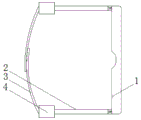
Glasses with anti-drop structure
Technical Field
The utility model relates to a glasses technical field specifically is a glasses with anti-drop structure.
Background
Glasses are combined by lenses and a frame to be worn in front of the eyes for improving eyesight and protecting the eyes or used as ornaments, and can correct various eyesight problems, including myopia, hyperopia, astigmatism, presbyopia or strabismus, amblyopia and the like, the glasses comprise lenses and a frame, and are divided into myopia glasses, hyperopia glasses, presbyopia glasses, astigmia glasses, plano glasses, computer goggles, swimming glasses, night vision goggles, electronic competition goggles, sunglasses, toy glasses and sunglasses, 15 types of special glasses are also provided for watching 3D stereoscopic images or virtual real images, other types of the glasses comprise goggles, sunglasses, swimming glasses and the like, various protections are provided for the eyes, modern glasses are generally provided with a nose support in the middle of the lenses, and cushions are arranged at the positions of the left arm and the right arm on the ears, and people who love or are not used for wearing the glasses, optionally, vision can be corrected with contact lenses.
Glasses are as the indispensable visual auxiliary equipment of present people, and no matter the age all has worn, thereby current children lead to glasses to drop owing to transfer the skin when wearing glasses, lead to glasses to damage, can not satisfy the user demand.
SUMMERY OF THE UTILITY MODEL
An object of the utility model is to provide a glasses with anti-drop structure possesses anti-drop's advantage, thereby has solved current children and has leaded to glasses to drop owing to transfer the skin when wearing glasses to lead to the problem of glasses damage.
In order to achieve the above object, the utility model provides a following technical scheme: the utility model provides a glasses with anti-drop structure, includes the spectacle frame, the left side of spectacle frame articulates through the activity has two glasses legs, the left side of glasses leg is provided with the installation piece, the left side fixed mounting of installation piece has the elastic cord, the elastic cord extends and pastes fixed connection through the magic to one side that is close to relatively, the holding tank has been seted up to the inside of installation piece, the inside of installation piece is provided with the kelly, the inside of installation piece is provided with the mounting panel, the glasses leg runs through the inside to the installation piece through the holding tank.
Preferably, the clamping rod is fixedly connected with the mounting block through the accommodating groove, the clamping groove is formed in the left side of the glasses leg, and the clamping rod penetrates through the inside of the clamping groove and is clamped to the inside of the clamping groove through the triangular clamping block.
Preferably, two mounting grooves have all been seted up to the inside of holding tank and the one side of keeping away from the glasses leg, the inside sliding connection of mounting groove has the gag lever post, one side and the mounting panel fixed connection that the gag lever post is close to the glasses leg, the inside cover that the surface of gag lever post just is located the mounting groove is equipped with the spring.
Preferably, the inside of installation piece and the both sides that are located the mounting groove have all seted up the spout, the inside sliding connection of spout has the slider, the one side and the spring fixed connection that the slider is close to relatively.
Preferably, one side of the mounting plate close to the glasses legs is fixedly provided with clamping balls which are uniformly distributed, and the mounting plate and the glasses legs are fixed through the clamping balls.
Compared with the prior art, the beneficial effects of the utility model are as follows:
1. the utility model discloses a cooperation between elastic cord and the installation piece is realized fixing spectacle frame and glasses leg, is used for realizing being connected between installation piece and the glasses leg through setting up the kelly, is used for supplementary fixing installation piece and glasses leg through setting up the mounting panel, prevents that spectacle frame and glasses leg from droing when using, thereby has solved current children simultaneously and has leaded to glasses to drop easily owing to transfer the skin when wearing glasses to lead to the problem that glasses damaged.
2. The utility model discloses a set up the draw-in groove and be used for holding the kelly, be used for increasing the stability between kelly and the glasses leg through setting up the triangle-shaped fixture block, be used for installing the gag lever post through setting up the mounting groove, be used for fixing the mounting panel through setting up the gag lever post, through the spring, cooperation between gag lever post and the mounting panel is realized fixing the glasses leg, prevent that glasses leg and installation piece from breaking away from, thereby lead to the spectacle frame to drop, realize spacing the gag lever post through the cooperation between spout and the slider, prevent that gag lever post and installation piece from droing and blockking the inside that the glasses leg runs through to the installation piece, be used for increasing the stability between mounting panel and the glasses leg through setting up the card ball, prevent that glasses leg and mounting panel from droing and leading.
Drawings
FIG. 1 is a schematic structural view of the present invention;
FIG. 2 is a schematic cross-sectional structure view of the mounting block of the present invention;
fig. 3 is a partially enlarged view of a portion a in fig. 2 according to the present invention.
In the figure: 1. a spectacle frame; 2. a spectacle leg; 3. elastic bands; 4. mounting blocks; 5. a clamping rod; 6. a card slot; 7. blocking the ball; 8. mounting a plate; 9. accommodating grooves; 10. a chute; 11. mounting grooves; 12. a spring; 13. a limiting rod; 14. a slide block.
Detailed Description
The technical solutions in the embodiments of the present invention will be described clearly and completely with reference to the accompanying drawings in the embodiments of the present invention, and it is obvious that the described embodiments are only some embodiments of the present invention, not all embodiments. Based on the embodiments in the present invention, all other embodiments obtained by a person skilled in the art without creative work belong to the protection scope of the present invention.
In the description herein, it is to be understood that the terms "center," "upper," "lower," "front," "rear," "left," "right," "vertical," "horizontal," "top," "bottom," "inner," "outer," and the like are used in the orientations and positional relationships indicated in the drawings to facilitate the description of the patent and to simplify the description, but do not indicate or imply that the referenced device or element must have a particular orientation, be constructed and operated in a particular orientation, and thus are not to be considered limiting of the patent. In the description of the present application, it should be noted that unless otherwise explicitly stated or limited, the terms "mounted," "connected," and "disposed" are to be construed broadly and can, for example, be fixedly connected, disposed, detachably connected, disposed, or integrally connected and disposed. The specific meaning of the above terms in this patent may be understood by those of ordinary skill in the art as appropriate.
Referring to fig. 1-3, a pair of glasses with an anti-falling structure comprises a glasses frame 1, two glasses legs 2 are movably hinged on the left side of the glasses frame 1, an installation block 4 is arranged on the left side of the glasses legs 2, an elastic band 3 is fixedly installed on the left side of the installation block 4, the elastic band 3 extends to one side close to the glasses frame and is fixedly connected with the glasses frame through a magic tape, an accommodating groove 9 is formed in the installation block 4, a clamping rod 5 is arranged in the installation block 4, an installation plate 8 is arranged in the installation block 4, the glasses legs 2 penetrate through the accommodating groove 9 to the inside of the installation block 4, the glasses frame 1 and the glasses legs 2 are fixed through the matching between the elastic band 3 and the installation block 4, the clamping rod 5 is arranged to realize the connection between the installation block 4 and the glasses legs 2, the installation plate 8 is arranged to assist in fixing the installation block 4, the glasses frame 1 and the glasses legs 2 are prevented from falling off when in use, the clamping rod 5 is fixedly connected with the mounting block 4 through the accommodating groove 9, the left side of the glasses legs 2 is provided with a clamping groove 6, the clamping rod 5 penetrates into the clamping groove 6 and is clamped into the clamping groove 6 through a triangular clamping block, the clamping rod 5 is accommodated through the clamping groove 6, the stability between the clamping rod 5 and the glasses legs 2 is increased through the triangular clamping block, two mounting grooves 11 are respectively formed in the accommodating groove 9 and one side far away from the glasses legs 2, the limiting rod 13 is slidably connected in the mounting grooves 11, one side of the limiting rod 13 close to the glasses legs 2 is fixedly connected with the mounting plate 8, the spring 12 is sleeved on the surface of the limiting rod 13 and in the mounting grooves 11, the mounting groove 11 is used for mounting the limiting rod 13, and the limiting rod 13 is used for fixing the mounting plate 8 through the limiting, the glasses legs 2 are fixed through the matching among the spring 12, the limiting rod 13 and the mounting plate 8, the glasses legs 2 are prevented from being separated from the mounting block 4, thereby leading the spectacle frame 1 to fall down, the inner part of the mounting block 4 and the two sides of the mounting groove 11 are both provided with the sliding grooves 10, the inner part of the sliding groove 10 is connected with the sliding block 14 in a sliding way, one side of the sliding block 14 which is relatively close to is fixedly connected with the spring 12, the limiting rod 13 is limited through the matching between the sliding groove 10 and the sliding block 14, the limiting rod 13 and the mounting block 4 are prevented from falling off to block the glasses legs 2 from penetrating into the mounting block 4, the side of the mounting plate 8 close to the glasses legs 2 is fixedly provided with the clamping balls 7 which are uniformly distributed, the mounting plate 8 and the glasses legs 2 are fixed through the clamping balls 7, the clamping ball 7 is used for increasing the stability between the mounting plate 8 and the glasses legs 2, and the glasses legs 2 and the mounting plate 8 are prevented from falling off to cause the mounting block 4 and the glasses legs 2 to fall off.
During the use, if need prevent to drop and run through the inside to installation piece 4 with glasses leg 2 through holding tank 9 for the kelly 5 runs through to the inside of draw-in groove 6 and is fixed with draw-in groove 6 through triangle-shaped fixture block, and the inside to mounting panel 8 is run through to calorie ball 7 simultaneously, thereby through spring 12, gag lever post 13 and slider 14 push up mounting panel 8 to the one side that is close to glasses leg 2 and fix glasses leg 2, will wholly wear to accomplish the back, it can to fix through elastic cord 3 and magic subsides.
Although embodiments of the present invention have been shown and described, it will be appreciated by those skilled in the art that changes, modifications, substitutions and alterations can be made in these embodiments without departing from the principles and spirit of the invention, the scope of which is defined in the appended claims and their equivalents.