A special cleaning device for bridge expansion joint
Technical Field
The utility model relates to an expansion joint technical field specifically is a special cleaning device for bridge expansion joint.
Background
Bridge expansion joints: it means that in order to meet the requirement of bridge deck deformation, expansion joints are usually arranged between two beam ends, between the beam ends and a bridge abutment or at the hinged position of a bridge, the expansion joints are required to freely expand and contract in two directions parallel to and perpendicular to the axis of the bridge, the expansion joints are firm and reliable, when a vehicle runs, the expansion joints are smooth, have no sudden jump and noise, can prevent rainwater and garbage and soil from permeating and blocking, and are simple and convenient to install, check, maintain and eliminate dirt, at the position of the expansion joint, the handrail and the bridge deck pavement are disconnected, a large amount of mud is accumulated in the joint in the long-term use process of the bridge expansion joint, the effect of the expansion joint is influenced, and therefore the expansion joint needs to be cleaned regularly, because the clearance that the expansion joint was carried out to the tradition is mostly cleared up through artifical manual, wastes time and energy, and work efficiency is lower, for this reason we propose a special cleaning device for bridge expansion joint and be used for solving above-mentioned problem.
SUMMERY OF THE UTILITY MODEL
An object of the utility model is to provide a special cleaning device for bridge expansion joint to solve and to provide in the above-mentioned background art because the tradition carries out the clearance at expansion joint most and clears up through artifical manual, waste time and energy, the lower problem of work efficiency.
In order to achieve the above object, the utility model provides a following technical scheme: a special cleaning device for a bridge expansion joint comprises a fixed platform, wherein a cleaning assembly is mounted at the bottom end of the fixed platform and comprises a motor, a driving gear, a driven gear, an arc gear, a positioning block, a positioning rod, a movable plate, a rack, a hydraulic rod, a fixed block, a mounting plate, a brush plate and a spray head;
the utility model discloses a fixed station, including fixed station, driving gear, locating piece, locating plate, fly leaf bottom middle part fixed mounting have a hydraulic stem, hydraulic stem piston one end fixed mounting in fixed block top, fixed block one end fixedly connected with driving gear, the driving gear outside both ends all mesh there is driven gear, driven gear one end middle part fixedly connected with arc gear, the equal fixed mounting in fixed station bottom both sides has the locating piece, locating piece side both ends are all fixed to run through there is the locating lever, the fly leaf has been cup jointed in the activity of the locating lever outside, the rack is all evenly installed to the fly leaf both sides, fly leaf bottom middle part fixed mounting has a hydraulic stem, hydraulic stem piston one end fixed mounting in the fixed block top, fixed block one end fixedly connected with.
Preferably, the other end of the driven gear is rotatably connected to the bottom end of the fixed table, and the arc-shaped gear is meshed with the rack on one side of the movable plate.
Preferably, both sides of the top end of the brush plate are provided with fixing holes corresponding to the spray heads.
Preferably, the water tank is installed on the fixed station top, the water tank side is fixed to run through there is the outlet pipe, outlet pipe one end is connected with the water pump end of intaking, water pump input and external power supply output electric connection, water pump water outlet end fixedly connected with shunt tubes, the equal fixedly connected with water hose in shunt tubes both ends, water hose one end and shower nozzle fixed connection.
Preferably, the top end of the mounting plate is provided with a fixing assembly, and the fixing assembly comprises a first limiting block, a limiting hole, a second limiting block, a limiting screw and a threaded hole;
the brush board is characterized in that first stoppers are fixedly mounted on two sides of the top end of the brush board, limiting holes corresponding to the first stoppers are formed in two sides of the top end of the mounting board, second stoppers are fixedly mounted on two sides of the top end of the mounting board, limiting screws penetrate through one ends of the second stoppers through thread activities, and threaded holes corresponding to the limiting screws are formed in one ends of the first stoppers.
Preferably, a pushing handle is installed at one end of the fixed table, movable wheels are installed at four corners of the bottom end of the fixed table, and a balancing weight is installed on one side of the top end of the fixed table.
Compared with the prior art, the beneficial effects of the utility model are that:
1. drive the driving gear through the motor and rotate, thereby drive two driven gear and arc gear syntropy and rotate, thereby make both sides arc gear syntropy rotate time intermittent type nature respectively in the rack toothing of both sides, thereby make the fly leaf corresponding reciprocating motion that makes a round trip on the locating lever, thereby drive the brush board and carry out the back and forth movement and please sweep the earth in the expansion joint, make earth not hard up, then the effect of cooperation shower nozzle, earth in with the expansion joint is washed cleanly through the high-pressure water spray, the cleaning performance is showing, reduce workman intensity of labour.
2. Through twisting out limit screw to make first stopper and second stopper drop and connect, thereby can separate brush board and mounting panel, thereby the later stage of being convenient for is changed excessive brush board of wearing and tearing.
Drawings
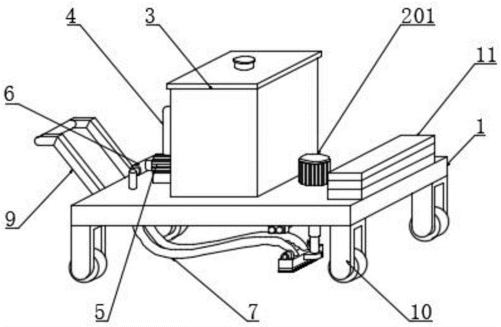
FIG. 1 is a schematic structural view of the present invention;
FIG. 2 is a schematic structural view of a cleaning assembly of the present invention;
FIG. 3 is a schematic view of the mounting structure of the mounting plate of the present invention;
fig. 4 is a schematic structural view of the middle fixing component of the present invention.
In the figure: 1. a fixed table;
2. cleaning the assembly; 201. a motor; 202. a driving gear; 203. a driven gear; 204. an arc gear; 205. positioning blocks; 206. positioning a rod; 207. a movable plate; 208. a rack; 209. a hydraulic lever; 210. a fixed block; 211. mounting a plate; 212. brushing the board; 213. a spray head;
3. a water tank; 4. a water outlet pipe; 5. a water pump; 6. a shunt tube; 7. a water delivery hose;
8. a fixing assembly; 801. a first stopper; 802. a limiting hole; 803. a second limiting block; 804. a limit screw; 805. a threaded hole;
9. a pushing handle; 10. a movable wheel; 11. and a balancing weight.
Detailed Description
The technical solutions in the embodiments of the present invention will be described clearly and completely with reference to the accompanying drawings in the embodiments of the present invention, and it is obvious that the described embodiments are only some embodiments of the present invention, not all embodiments. Based on the embodiments in the present invention, all other embodiments obtained by a person skilled in the art without creative work belong to the protection scope of the present invention.
Referring to fig. 1-4, the present invention provides a technical solution: a special cleaning device for a bridge expansion joint comprises a fixed platform 1, wherein a cleaning assembly 2 is installed at the bottom end of the fixed platform 1, and the cleaning assembly 2 comprises a motor 201, a driving gear 202, a driven gear 203, an arc gear 204, a positioning block 205, a positioning rod 206, a movable plate 207, a rack 208, a hydraulic rod 209, a fixed block 210, a mounting plate 211, a brush plate 212 and a spray head 213;
a motor 201 is fixedly arranged at the top end of a fixed table 1, the input end of the motor 201 is electrically connected with the output end of an external power supply, one end of the output shaft of the motor 201 is fixedly connected with a driving gear 202, two ends of the outer side of the driving gear 202 are respectively engaged with a driven gear 203, the middle part of one end of the driven gear 203 is fixedly connected with an arc gear 204, two sides of the bottom end of the fixed table 1 are respectively fixedly provided with a positioning block 205, two ends of the side surface of the positioning block 205 are respectively fixedly provided with a positioning rod 206, the outer side of the positioning rod 206 is movably sleeved with a movable plate 207, two sides of the movable plate 207 are respectively and uniformly provided with a rack 208, the middle part of the bottom end of the movable plate 207 is fixedly provided with a hydraulic rod 209, one end of a piston of the hydraulic rod 209 is, the arc gears 204 are engaged with the rack 208 on one side of the movable plate 207, so as to drive the driven gears 203 on two sides to rotate in the same direction through the driving gear 202, so that the corresponding arc gears 204 rotate in the same direction, the arc gears 204 on two sides are intermittently engaged with the racks 208 on two sides of the movable plate 207 respectively, so as to drive the movable plate 207 to reciprocate, so as to enable the brush plate 212 to move back and forth and clean the expansion joint, both sides of the top end of the brush plate 212 are provided with fixing holes corresponding to the spray heads 213, so as to facilitate the spray heads 213 to clean the expansion joint, the top end of the fixed platform 1 is provided with the water tank 3, the side surface of the water tank 3 is fixedly penetrated with the water outlet pipe 4, one end of the water outlet pipe 4 is connected with the water inlet end of the water pump 5, the input end of the water pump 5 is electrically connected with, one end of the water hose 7 is fixedly connected with the spray heads 213, so that water can be conveniently supplied to the two spray heads 213.
The top end of the mounting plate 211 is provided with a fixing component 8, and the fixing component 8 comprises a first limit block 801, a limit hole 802, a second limit block 803, a limit screw 804 and a threaded hole 805;
brush board 212 top both sides equal fixed mounting have first stopper 801, mounting panel 211 top both sides all set up the spacing hole 802 that corresponds with first stopper 801, mounting panel 211 top both sides equal fixed mounting has second stopper 803, second stopper 803 one end runs through there is stop screw 804 through the screw thread activity, screw hole 805 that corresponds with stop screw 804 is seted up to first stopper 801 one end, be convenient for brush the installation of board 212 and the change in later stage, 1 one end of fixed station is installed and is promoted 9, movable wheel 10 is all installed to 1 bottom four corners position department of fixed station, the removal of the device of being convenient for, balancing weight 11 is installed to 1 top one side of fixed station.
The working principle is as follows: when cleaning the expansion joint, the device is moved to the position of the expansion joint by pushing the handle 9, the hydraulic rod 209 is started to make the brush plate 212 adhere to the surface of the expansion joint, the motor 201 is started to make the motor 201 drive the driving gear 202 to rotate, because two sides of the driving gear 202 are respectively meshed with the two driven gears 203, the two driven gears 203 and the arc gears 204 rotate in the same direction, and the two arc gears 204 can be respectively meshed with the racks 208 on two sides of the movable plate 207, so that when the arc gears 204 on two sides rotate in the same direction, the arc gears can be intermittently meshed with the racks 208 on the movable plate 207, and the movable plate 207 is driven to correspondingly slide back and forth on the positioning rod 206, so that the iron through cover hydraulic rod 209 drives the mounting plate 211 and the brush plate 212 to perform reciprocating motion in a certain space, thereby the brush plate 212 cleans the soil in the expansion joint, the soil is loosened, the water pump 5 is started at the same, the expansion joint is washed by the high-pressure water sprayed by the spray head 213, so that the operation is convenient and the labor is saved;
when the brush plate 212 is seriously worn and needs to be replaced, the limit screw 804 on the second limit block 803 is screwed out, so that the first limit block 801 and the second limit block 803 are disconnected, the first limit block 801 can penetrate through the corresponding limit hole 802, the brush plate 212 is separated from the mounting plate 211, and the brush plate 212 is convenient to replace.
Although embodiments of the present invention have been shown and described, it will be appreciated by those skilled in the art that changes, modifications, substitutions and alterations can be made in these embodiments without departing from the principles and spirit of the invention, the scope of which is defined in the appended claims and their equivalents.