CN212919682U - PI conduction band piercing press - Google Patents
PI conduction band piercing press Download PDFInfo
- Publication number
- CN212919682U CN212919682U CN202021431200.XU CN202021431200U CN212919682U CN 212919682 U CN212919682 U CN 212919682U CN 202021431200 U CN202021431200 U CN 202021431200U CN 212919682 U CN212919682 U CN 212919682U
- Authority
- CN
- China
- Prior art keywords
- plate
- fixedly connected
- roller
- fixed
- bottom plate
- Prior art date
- Legal status (The legal status is an assumption and is not a legal conclusion. Google has not performed a legal analysis and makes no representation as to the accuracy of the status listed.)
- Active
Links
- 230000007246 mechanism Effects 0.000 claims abstract description 40
- 238000004080 punching Methods 0.000 claims abstract description 37
- 238000007599 discharging Methods 0.000 claims abstract description 23
- 239000000463 material Substances 0.000 claims description 23
- 238000004804 winding Methods 0.000 claims description 14
- 230000001105 regulatory effect Effects 0.000 claims description 8
- 238000007664 blowing Methods 0.000 claims description 6
- 238000000034 method Methods 0.000 abstract description 7
- 230000008569 process Effects 0.000 abstract description 4
- 230000008878 coupling Effects 0.000 description 12
- 238000010168 coupling process Methods 0.000 description 12
- 238000005859 coupling reaction Methods 0.000 description 12
- 238000005096 rolling process Methods 0.000 description 4
- 230000009471 action Effects 0.000 description 3
- 238000004140 cleaning Methods 0.000 description 3
- 238000004519 manufacturing process Methods 0.000 description 2
- 239000004065 semiconductor Substances 0.000 description 2
- LFQSCWFLJHTTHZ-UHFFFAOYSA-N Ethanol Chemical compound CCO LFQSCWFLJHTTHZ-UHFFFAOYSA-N 0.000 description 1
- 230000004075 alteration Effects 0.000 description 1
- 230000009286 beneficial effect Effects 0.000 description 1
- 230000005540 biological transmission Effects 0.000 description 1
- 238000011065 in-situ storage Methods 0.000 description 1
- 230000004048 modification Effects 0.000 description 1
- 238000012986 modification Methods 0.000 description 1
- 238000006467 substitution reaction Methods 0.000 description 1
Images



Landscapes
- Perforating, Stamping-Out Or Severing By Means Other Than Cutting (AREA)
Abstract
The utility model discloses a PI conduction band punching machine, which comprises a bottom plate, a feeding plate, a discharging plate, a supporting column and a supporting plate, wherein the upper surface of the bottom plate is symmetrically and respectively fixedly connected with the feeding plate and the discharging plate, the supporting column is symmetrically arranged above the bottom plate, the supporting column is fixedly connected with the bottom plate, one end of the supporting column, which is far away from the bottom plate, is fixedly connected with the supporting plate, a discharging device is installed on the surface of the feeding plate in a rotating way, the upper surface of the supporting plate is fixedly connected with a punching mechanism, the punching mechanism is fixedly connected with the bottom plate, the upper surface of the bottom plate is positioned below the supporting plate and is fixedly connected with a traction mechanism, the utility model ensures the conduction band to be in a relatively tight state in the whole equipment operation process by adjusting the positions of a first adjusting roller and a second adjusting roller, ensures, the automation degree is high, the structure is simple, and the practicability is strong.
Description
Technical Field
The utility model relates to a semiconductor material production facility technical field specifically is a PI conduction band piercing press.
Background
The PI conduction band punching machine is a device for punching and cleaning a PI conduction band, is used as a semiconductor material in many electronic products and mechanical devices, and is an indispensable part of the components.
The existing PI conduction band production process is low in automation degree and affects punching quality, and therefore a PI conduction band punching machine is provided.
SUMMERY OF THE UTILITY MODEL
An object of the utility model is to provide a PI conduction band piercing press that degree of automation is high to solve the problem that proposes among the above-mentioned background art.
In order to achieve the above object, the utility model provides a following technical scheme: the utility model provides a PI conduction band piercing press, includes bottom plate, goes up flitch, support column and backup pad down, the upper surface symmetry of bottom plate is fixedly connected with goes up flitch and lower flitch respectively, there is the support column bottom plate top symmetry, support column and bottom plate fixed connection, it is a plurality of the one end fixedly connected with backup pad of bottom plate is kept away from to the support column, the surface rotation of going up the flitch installs the blowing device, the last fixed surface of backup pad is connected with the mechanism of punching a hole, the mechanism and bottom plate fixed connection of punching a hole, the bottom plate upper surface is located the below fixedly connected with drive mechanism of backup pad, drive mechanism and the mechanism fixed connection that punches a hole, the bottom plate upper surface is located drive mechanism's fixedly connected with wiper mechanism on the right.
Preferably, the discharging device comprises a first servo motor, a discharging wheel, a first guide roller, a first adjusting roller and a first positioning roller, the surface of the feeding plate is provided with the first servo motor, the output end of the first servo motor is fixedly connected with the discharging wheel, the first guide roller is symmetrically arranged below the discharging wheel, the first guide roller is fixedly connected with the feeding plate, the surface of the feeding plate is provided with the first adjusting roller in a sliding manner, and the surface of the feeding plate is provided with the first positioning roller fixedly connected to the right of the first adjusting roller.
Preferably, the punching mechanism comprises a rotating motor, a mounting plate, a shaft coupling, a fixed shaft, a fixed seat, a connecting plate, a connecting seat, a connecting rod, a punching module, a first fixed platform, a receiving roller and a punching plate, the mounting plate is fixedly connected to the upper surface of the supporting plate, the surface of the mounting plate is provided with the rotating motor, the output end of the rotating motor is fixedly connected with the shaft coupling, one end of the shaft coupling, which is far away from the rotating motor, is fixedly connected with the fixed shaft, one end of the fixed shaft, which is far away from the shaft coupling, is rotatably connected with the fixed seat, the fixed seat is fixedly connected with the supporting plate, the surface of the fixed shaft is fixedly connected with an eccentric wheel, the connecting plate is installed by the surface rotation of the eccentric wheel, the connecting seat is fixedly connected below the, a first fixing platform is arranged above the bottom plate and fixedly connected with the bottom plate, a material receiving roller is installed on the surface of the first fixing platform in a rotating mode, and a punching plate is fixedly connected to the right side of the first fixing platform.
Preferably, the traction mechanism comprises a driving motor, a fixing plate, a lead screw, a sliding groove, a sliding block, a drag chain, an L-shaped plate, a vertical plate, a first traction plate, a second traction plate, a driving structure and a second fixing platform, wherein the upper surface of the bottom plate is positioned at the right end of the punching plate and is fixedly connected with the second fixing platform, the surface of the second fixing platform is slidably provided with the second traction plate, the upper surface of the bottom plate is positioned beside the second fixing platform and is fixedly connected with the fixing plate, the surface of the fixing plate is provided with the sliding groove, the side wall of the fixing plate is provided with the driving motor, the output end of the driving motor is fixedly connected with the lead screw, the lead screw is rotatably connected with the fixing plate, the surface of the lead screw is connected with the sliding block through a thread, the sliding block is slidably connected with the sliding groove, the second traction plate is fixedly connected, the surface fixed connection of L template has the tow chain, the other end and the bottom plate fixed connection of tow chain, the last fixed surface of slider is connected with the riser, the riser is kept away from the one end of slider and is installed the drive structure, the first traction plate of below fixed connection of drive structure.
Preferably, the winding device comprises a second servo motor, a winding wheel, a material receiving roller, a second adjusting roller, a second positioning roller and a second guide roller, the second servo motor is arranged on the surface of the lower material plate, the winding wheel is fixedly connected with the output end of the second servo motor, the second guide roller is symmetrically arranged below the winding wheel, the second guide roller is fixedly connected with the lower material plate, the second adjusting roller is slidably arranged below the second guide roller on the surface of the lower material plate, and the second positioning roller and the material receiving roller are respectively arranged on the left side and the right side of the second adjusting roller.
Preferably, the surfaces of the upper material plate and the lower material plate are symmetrically and fixedly connected with a triangular plate.
Compared with the prior art, the beneficial effects of the utility model are that:
the utility model uses a first servo motor to drive the conduction band to pass through the left first guide roll, the first adjusting roll, the right first guide roll and the surface of the first positioning roll from the discharging wheel, and then enter the lower part of the support plate, and the conduction band is ensured not to have a relatively loose state by adjusting the up-and-down movement of the first adjusting roll, the conduction band is guided and positioned by the receiving roll, the conduction band passes through the lower part of the punching module and reaches between the first traction plate and the second traction plate, the driving motor is started to drive the lead screw to rotate, and further to drive the slider which is in threaded connection with the lead screw, and simultaneously, the driving structure drives the first traction plate to move downwards to be matched with the second traction plate to clamp the conduction band, and drives the conduction band to move towards the direction of the cleaning mechanism, the driving motor drives the lead screw to rotate backwards after the slider is ready to be in situ, the repeated operation can realize the continuous, the driving shaft coupling rotates, the fixed axle and shaft coupling fixed connection, the fixed surface fixed connection of fixed axle has the eccentric wheel, and then the driving eccentric wheel rotates, the eccentric wheel rotates and drives the connecting plate and reciprocate, drive the module that punches a hole through connecting seat and connecting rod transmission and reciprocate and punch a hole, wash through wiper mechanism again, the conduction band passes through the top of second positioning roller, pass through the below of second regulating roller and the below of receiving the material roller, reach the top of the second guide roller on the right again, pass through the below of the second guide roller on the left, drive the rolling wheel rolling by second servo motor again, whole process need not artifical the participation, degree of automation is high, through the regulatory action of first regulating roller and second regulating roller, avoid the conduction band to be in lax state in whole course of working, guarantee the quality of punching a hole.
Drawings
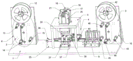
FIG. 1 is a schematic view of the overall structure of the present invention;
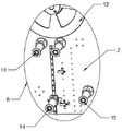
FIG. 2 is a schematic view of the structure of the discharging device of the present invention;
FIG. 3 is a schematic view of the structure of the punching mechanism of the present invention;
FIG. 4 is a schematic structural view of the traction mechanism of the present invention;
fig. 5 is a partially enlarged structural schematic view of the first traction plate and the second traction plate of the present invention;
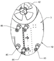
FIG. 6 is a schematic view of the rolling device of the present invention;
fig. 7 is a second schematic view of the overall structure of the present invention.
In the figure: 1. a base plate; 2. feeding plates; 3. a blanking plate; 4. a support pillar; 5. a support plate; 6. a discharging device; 7. a punching mechanism; 8. a traction mechanism; 9. a cleaning mechanism; 10. a winding device; 11. a first servo motor; 12. a discharge wheel; 13. a first guide roller; 14. a first regulating roller; 15. a first positioning roller; 16. rotating the motor; 17. mounting a plate; 18. a coupling; 19. a fixed shaft; 20. a fixed seat; 21. a connecting plate; 22. a connecting seat; 23. a connecting rod; 24. a punching module; 25. a first fixed platform; 26. a receiving roller; 27. punching a plate; 28. a drive motor; 29. a fixing plate; 30. a screw rod; 31. A chute; 32. a slider; 33. a set square; 34. a drag chain; 35. an L-shaped plate; 36. a vertical plate; 37. a first traction plate; 38. a second traction plate; 39. a drive structure; 40. a second stationary platform; 41. a second servo motor; 42. a winding wheel; 43. a material receiving roller; 44. a second dancer roll; 45. a second positioning roller; 46. A second guide roller.
Detailed Description
The technical solutions in the embodiments of the present invention will be described clearly and completely with reference to the accompanying drawings in the embodiments of the present invention, and it is obvious that the described embodiments are only some embodiments of the present invention, not all embodiments. Based on the embodiments in the present invention, all other embodiments obtained by a person skilled in the art without creative work belong to the protection scope of the present invention.
Referring to fig. 1, a PI conduction band punching machine comprises a bottom plate 1, a feeding plate 2, a discharging plate 3, support columns 4 and support plates 5, wherein the feeding plate 2 and the discharging plate 3 are symmetrically and fixedly connected to the upper surface of the bottom plate 1, the support columns 4 are symmetrically arranged above the bottom plate 1, the support columns 4 are fixedly connected to the bottom plate 1, one ends of the support columns 4 far away from the bottom plate 1 are fixedly connected to the support plates 5, a discharging device 6 is rotatably mounted on the surface of the feeding plate 2, so that the conduction band can not be in a loose state during discharging, a punching mechanism 7 is fixedly connected to the upper surface of the support plates 5, the punching mechanism 7 is fixedly connected to the bottom plate 1, a traction mechanism 8 is fixedly connected to the lower portion of the support plates 5 on the upper surface of the bottom plate 1, the conduction band after punching is pulled, and the traction mechanism 8 is fixedly connected to the punching mechanism 7, the right fixedly connected with wiper mechanism 9 that bottom plate 1 upper surface was located drive mechanism 8 washs the mechanism 9 for current abluent structure of alcohol to the conduction band, washs the conduction band, the surface rotation of flitch 3 down installs coiling mechanism 10, can carry out the rolling to the conduction band after the counterboring washs.
Referring to fig. 2, the discharging device 6 includes a first servo motor 11, a discharging wheel 12, a first guide roller 13, a first adjusting roller 14 and a first positioning roller 15, the first servo motor 11 is installed on the surface of the feeding plate 2, the discharging wheel 12 is fixedly connected to the output end of the first servo motor 11, the first guide roller 13 is symmetrically arranged below the discharging wheel 12, the first guide roller 13 is fixedly connected to the feeding plate 2, the first adjusting roller 14 is slidably installed on the surface of the feeding plate 2, which is located on the surface of the first guide roller 13, the first positioning roller 15 is fixedly connected to the right of the first adjusting roller 14, and the discharging wheel 12 is driven by the first servo motor 11 to rotate for discharging.
Referring to fig. 3, the punching mechanism 7 includes a rotating motor 16, a mounting plate 17, a coupling 18, a fixing shaft 19, a fixing seat 20, a connecting plate 21, a connecting seat 22, a connecting rod 23, a punching module 24, a first fixing platform 25, a material receiving roller 26 and a punching plate 27, the mounting plate 17 is fixedly connected to the upper surface of the supporting plate 5, the rotating motor 16 is mounted on the surface of the mounting plate 17, the coupling 18 is fixedly connected to the output end of the rotating motor 16, the fixing shaft 19 is fixedly connected to one end of the coupling 18 far away from the rotating motor 16, the fixing seat 20 is rotatably connected to one end of the surface of the fixing shaft 19 far away from the coupling 18, the fixing seat 20 is fixedly connected to the supporting plate 5, an eccentric wheel is fixedly connected to the surface of the fixing shaft 19, the connecting plate 21 is rotatably mounted, connecting seat 22's below symmetry fixedly connected with connecting rod 23, it is a plurality of connecting rod 23 keeps away from connecting seat 22's one end fixedly connected with module 24 that punches a hole, first fixed platform 25 has been put to bottom plate 1 top, first fixed platform 25 and 1 fixed connection of bottom plate, first fixed platform 25's surface rotation installs and connects material roller 26, the board 27 that punches a hole is punched to first fixed platform 25's the fixedly connected with on the right can continuously punch a hole to the conduction band, and shaft coupling 18 can guarantee that rotation motor 16 can not damage because of transshipping, and module 24 that punches a hole is current to the structure of punching a hole of conduction band, for prior art.
Referring to fig. 4, the traction mechanism 8 includes a driving motor 28, a fixed plate 29, a screw rod 30, a sliding groove 31, a sliding block 32, a drag chain 34, an L-shaped plate 35, a vertical plate 36, a first traction plate 37, a second traction plate 38, a driving structure 39 and a second fixed platform 40, the second fixed platform 40 is fixedly connected to the right end of the punching plate 27 on the upper surface of the base plate 1, the second traction plate 38 is slidably mounted on the surface of the second fixed platform 40, the fixed plate 29 is fixedly connected to the side of the second fixed platform 40 on the upper surface of the base plate 1, the sliding groove 31 is formed on the surface of the fixed plate 29, the driving motor 28 is mounted on the side wall of the fixed plate 29, the screw rod 30 is fixedly connected to the output end of the driving motor 28, the screw rod 30 is rotatably connected to the fixed plate 29, the sliding block 32 is connected to the surface of the screw rod 30, second traction plate 38 and slider 32 fixed connection, L template 35 has been put to the top of slider 32, L template 35 and slider 32 fixed connection, the fixed surface of L template 35 is connected with tow chain 34, the other end and bottom plate 1 fixed connection of tow chain 34, the last fixed surface of slider 32 is connected with riser 36, drive structure 39 is installed to the one end that slider 32 was kept away from to riser 36, the first traction plate 37 of below fixedly connected with of drive structure 39 pulls the conduction band after crossing the punching hole, and drive structure 39 is similar with current robotic arm vertical lift structure, and its theory of operation is the same, for current mature technique.
Referring to fig. 6, the winding device 10 includes a second servo motor 41, a winding wheel 42, a material receiving roller 43, a second adjusting roller 44, a second positioning roller 45 and a second guiding roller 46, the second servo motor 41 is installed on the surface of the blanking plate 3, the winding wheel 42 is fixedly connected to the output end of the second servo motor 41, the second guiding roller 46 is symmetrically arranged below the winding wheel 42, the second guiding roller 46 is fixedly connected to the blanking plate 3, the second adjusting roller 44 is slidably installed on the surface of the blanking plate 3 below the second guiding roller 46, and the second positioning roller 45 and the material receiving roller 43 are respectively installed on the left side and the right side of the second adjusting roller 44, so as to wind the punched and cleaned conduction band.
The surfaces of the feeding plate 2 and the discharging plate 3 are symmetrically and fixedly connected with a triangular plate 33, and the feeding plate 2 and the discharging plate 3 are assisted to keep stable.
It is noted that, herein, relational terms such as first and second, and the like may be used solely to distinguish one entity or action from another entity or action without necessarily requiring or implying any actual such relationship or order between such entities or actions. Also, the terms "comprises," "comprising," or any other variation thereof, are intended to cover a non-exclusive inclusion, such that a process, method, article, or apparatus that comprises a list of elements does not include only those elements but may include other elements not expressly listed or inherent to such process, method, article, or apparatus.
Although embodiments of the present invention have been shown and described, it will be appreciated by those skilled in the art that changes, modifications, substitutions and alterations can be made in these embodiments without departing from the principles and spirit of the invention, the scope of which is defined in the appended claims and their equivalents.
Claims (6)
1. The utility model provides a PI conduction band piercing press, includes bottom plate (1), goes up flitch (2), unloading board (3), support column (4) and backup pad (5), the upper surface symmetry of bottom plate (1) is flitch (2) and unloading board (3) on fixedly connected with respectively, bottom plate (1) top symmetry has put support column (4), support column (4) and bottom plate (1) fixed connection, and is a plurality of one end fixedly connected with backup pad (5) of bottom plate (1), its characterized in that are kept away from in support column (4): go up the surface rotation of flitch (2) and install blowing device (6), the last fixed surface of backup pad (5) is connected with mechanism (7) of punching a hole, mechanism (7) and bottom plate (1) fixed connection punch a hole, bottom plate (1) upper surface is located below fixedly connected with drive mechanism (8) of backup pad (5), drive mechanism (8) and mechanism (7) fixed connection punch a hole, bottom plate (1) upper surface is located right fixedly connected with wiper mechanism (9) of drive mechanism (8), coiling mechanism (10) are installed in the surface rotation of flitch (3) down.
2. A PI conduction band punch as claimed in claim 1, wherein: blowing device (6) include first servo motor (11), blowing wheel (12), first guide roll (13), first regulating roller (14) and first registration roller (15), the surface mounting who goes up flitch (2) has first servo motor (11), the output fixedly connected with blowing wheel (12) of first servo motor (11), the below symmetry of blowing wheel (12) has first guide roll (13), first guide roll (13) and last flitch (2) fixed connection, the surface sliding who goes up flitch (2) the surface and is located first guide roll (13) installs first regulating roller (14), the surface of going up flitch (2) is located the first registration roller (15) of the right fixedly connected with of first regulating roller (14).
3. A PI conduction band punch as claimed in claim 1, wherein: the punching mechanism (7) comprises a rotating motor (16), a mounting plate (17), a coupler (18), a fixed shaft (19), a fixed seat (20), a connecting plate (21), a connecting seat (22), a connecting rod (23), a punching module (24), a first fixing platform (25), a material receiving roller (26) and a punching plate (27), wherein the mounting plate (17) is fixedly connected with the upper surface of the supporting plate (5), the rotating motor (16) is mounted on the surface of the mounting plate (17), the coupler (18) is fixedly connected with the output end of the rotating motor (16), the fixed shaft (19) is fixedly connected with one end of the coupler (18) far away from the rotating motor (16), the fixed shaft (19) is rotatably connected with the fixed seat (20) at the surface far away from the end of the coupler (18), the fixed seat (20) is fixedly connected with the supporting plate (5), and the surface of the, the surface rotation of eccentric wheel installs connecting plate (21), the below fixedly connected with connecting seat (22) of connecting plate (21), the below symmetry fixedly connected with connecting rod (23) of connecting seat (22), it is a plurality of one end fixedly connected with punching module (24) of connecting seat (22) are kept away from in connecting rod (23), first fixed platform (25) have been put to bottom plate (1) top, first fixed platform (25) and bottom plate (1) fixed connection, material receiving roller (26) are installed in the surface rotation of first fixed platform (25), board (27) are punched in the fixedly connected with on the right of first fixed platform (25).
4. A PI conduction band punch as claimed in claim 1, wherein: the traction mechanism (8) comprises a driving motor (28), a fixing plate (29), a screw rod (30), a sliding groove (31), a sliding block (32), a drag chain (34), an L-shaped plate (35), a vertical plate (36), a first traction plate (37), a second traction plate (38), a driving structure (39) and a second fixing platform (40), the right end of the punching plate (27) on the upper surface of the base plate (1) is fixedly connected with the second fixing platform (40), the second traction plate (38) is slidably mounted on the surface of the second fixing platform (40), the fixing plate (29) is fixedly connected to the side of the second fixing platform (40) on the upper surface of the base plate (1), the sliding groove (31) is formed in the surface of the fixing plate (29), the driving motor (28) is mounted on the side wall of the fixing plate (29), the screw rod (30) is fixedly connected to the output end of the driving motor (28), lead screw (30) are rotated with fixed plate (29) and are connected, there is slider (32) on the surface of lead screw (30) through threaded connection, slider (32) and spout (31) sliding connection, second traction plate (38) and slider (32) fixed connection, L template (35) have been put to the top of slider (32), L template (35) and slider (32) fixed connection, the fixed surface of L template (35) is connected with tow chain (34), the other end and bottom plate (1) fixed connection of tow chain (34), the last fixed surface of slider (32) is connected with riser (36), drive structure (39) are installed to the one end that slider (32) were kept away from in riser (36), the first traction plate (37) of below fixed connection of drive structure (39).
5. A PI conduction band punch as claimed in claim 1, wherein: the winding device (10) comprises a second servo motor (41), a winding wheel (42), a material receiving roller (43), a second adjusting roller (44), a second positioning roller (45) and a second guide roller (46), the surface of the lower material plate (3) is provided with the second servo motor (41), the output end of the second servo motor (41) is fixedly connected with the winding wheel (42), the second guide roller (46) is symmetrically arranged below the winding wheel (42), the second guide roller (46) is fixedly connected with the lower material plate (3), the surface of the lower material plate (3) is positioned below the second guide roller (46) and is provided with the second adjusting roller (44) in a sliding manner, and the left side and the right side of the second adjusting roller (44) are respectively provided with the second positioning roller (45) and the material receiving roller (43).
6. A PI conduction band punch as claimed in claim 1, wherein: the surfaces of the feeding plate (2) and the discharging plate (3) are symmetrically and fixedly connected with a triangular plate (33).
Priority Applications (1)
| Application Number | Priority Date | Filing Date | Title |
|---|---|---|---|
| CN202021431200.XU CN212919682U (en) | 2020-07-20 | 2020-07-20 | PI conduction band piercing press |
Applications Claiming Priority (1)
| Application Number | Priority Date | Filing Date | Title |
|---|---|---|---|
| CN202021431200.XU CN212919682U (en) | 2020-07-20 | 2020-07-20 | PI conduction band piercing press |
Publications (1)
| Publication Number | Publication Date |
|---|---|
| CN212919682U true CN212919682U (en) | 2021-04-09 |
Family
ID=75331276
Family Applications (1)
| Application Number | Title | Priority Date | Filing Date |
|---|---|---|---|
| CN202021431200.XU Active CN212919682U (en) | 2020-07-20 | 2020-07-20 | PI conduction band piercing press |
Country Status (1)
| Country | Link |
|---|---|
| CN (1) | CN212919682U (en) |
-
2020
- 2020-07-20 CN CN202021431200.XU patent/CN212919682U/en active Active
Similar Documents
| Publication | Publication Date | Title |
|---|---|---|
| CN213224100U (en) | Straightening device for cable processing | |
| CN112474869A (en) | Three-roller extrusion device for welding sharp-angled square steel | |
| CN217191753U (en) | Steel sheet processing is with opening flat-bed machine that has surface structure of clearing up in advance | |
| CN214003494U (en) | Automatic equipment of rolling up of cloth | |
| CN221417012U (en) | Quartz tube cutting machine | |
| CN206691522U (en) | An automatic labeling machine based on PLC servo motor | |
| CN214242895U (en) | Stacking truss manipulator for polar plate stacking line | |
| CN111958676A (en) | PI conduction band piercing press | |
| CN118893150A (en) | A special-shaped copper foil blanking device and use method | |
| CN219401804U (en) | Square shell winding processing device | |
| CN218486895U (en) | Automatic winding machine of stamping device | |
| CN219192653U (en) | Material sheet type electronic component taping machine | |
| CN214022677U (en) | Three-roller extrusion device for welding sharp-angled square steel | |
| CN213559220U (en) | Shaping device for stainless steel plate | |
| CN215092657U (en) | Automatic wire drawing equipment of block terminal | |
| CN111618125B (en) | Stamping workpiece punching press rim charge winding batches and uses guide device | |
| CN212170692U (en) | Micro-spraying belt perforating machine | |
| CN211106650U (en) | Four-roller steel plate embossing device | |
| CN114378186A (en) | Automatic stamping device and process for copper connecting sheet | |
| CN202321700U (en) | Paper lifting device for impressing and gold stamping paper feeder | |
| CN217412222U (en) | Conveying and sorting device | |
| CN221258152U (en) | Bending machine convenient to move | |
| CN222332120U (en) | Product compacting device during continuous electroplating of strip | |
| CN217412197U (en) | Material pressing device of automatic material cutting machine for producing iron sheet glasses boxes | |
| CN222610422U (en) | Anti-wrinkle rolling device for composite fishing rod |
Legal Events
| Date | Code | Title | Description |
|---|---|---|---|
| GR01 | Patent grant | ||
| GR01 | Patent grant | ||
| TR01 | Transfer of patent right |
Effective date of registration: 20221223 Address after: Room 2003, No. 33 Xinggui Street, Suzhou Industrial Park, Suzhou Area, China (Jiangsu) Pilot Free Trade Zone, Suzhou City, Jiangsu Province, 215000 Patentee after: Suzhou Haoyajin Electronic Technology Co.,Ltd. Address before: 215000 1088 Fuyuan Road, Yuanhe street, Xiangcheng District, Suzhou City, Jiangsu Province Patentee before: Suzhou kaisatte Electronic Technology Co.,Ltd. |
|
| TR01 | Transfer of patent right |