CN212913378U - Medical instrument holds device - Google Patents

Medical instrument holds device Download PDF

Info

Publication number
CN212913378U
CN212913378U CN202020480931.7U CN202020480931U CN212913378U CN 212913378 U CN212913378 U CN 212913378U CN 202020480931 U CN202020480931 U CN 202020480931U CN 212913378 U CN212913378 U CN 212913378U
Authority
CN
China
Prior art keywords
cabinet body
platen
cabinet
strip
shaped plate
Prior art date
Legal status (The legal status is an assumption and is not a legal conclusion. Google has not performed a legal analysis and makes no representation as to the accuracy of the status listed.)
Expired - Fee Related
Application number
CN202020480931.7U
Other languages
Chinese (zh)
Inventor
梁宇棋
唐钒
李子好
石磊
Current Assignee (The listed assignees may be inaccurate. Google has not performed a legal analysis and makes no representation or warranty as to the accuracy of the list.)
Nanfang Hospital of Southern Medical University
Original Assignee
Nanfang Hospital of Southern Medical University
Priority date (The priority date is an assumption and is not a legal conclusion. Google has not performed a legal analysis and makes no representation as to the accuracy of the date listed.)
Filing date
Publication date
Application filed by Nanfang Hospital of Southern Medical University filed Critical Nanfang Hospital of Southern Medical University
Priority to CN202020480931.7U priority Critical patent/CN212913378U/en
Application granted granted Critical
Publication of CN212913378U publication Critical patent/CN212913378U/en
Expired - Fee Related legal-status Critical Current
Anticipated expiration legal-status Critical

Links

Images

Landscapes

  • Accommodation For Nursing Or Treatment Tables (AREA)

Abstract

本实用新型公开了一种医疗器械盛放装置,包括柜体,所述柜体的前端面设置有四个柜门,所述柜门远离柜体一侧的前端面均安装有门把手,所述柜体的上端面安装有台板B,所述柜体上方的一端固定安装有条形板,所述条形板的中间设置有滑槽,所述台板B靠近条形板一侧的外表面固定安装有滑块,所述台板B远离条形板的一端安装有台板A,所述台板A远离台板B一端的上表面设置有凹槽,所述凹槽的内部设置有拉手,所述柜体内壁的两侧均安装有九个限位块。本实用新型通过设置台板A、台板B、条形板、滑槽和滑块可以在取用较多所需医疗器械需要更多暂存台面时扩大台面的面积,不需要较大的台面时将台板A放下不占用空间,操作方便。

Figure 202020480931

The utility model discloses a medical device containing device, which comprises a cabinet body, four cabinet doors are arranged on the front end surface of the cabinet body, and door handles are installed on the front end surface of the cabinet door on the side away from the cabinet body. A platen B is installed on the upper end surface of the cabinet body, a strip-shaped plate is fixedly installed at one end above the cabinet body, a chute is arranged in the middle of the strip-shaped plate, and the platen B is close to one side of the strip-shaped plate. A slider is fixedly installed on the outer surface, a platen A is installed at one end of the platen B away from the strip plate, and a groove is provided on the upper surface of the end of the platen A away from the platen B, and the inside of the groove is arranged There are handles, and nine limit blocks are installed on both sides of the inner wall of the cabinet. The utility model can expand the area of the tabletop when more temporary storage tabletops are needed to obtain more required medical instruments by arranging the tableboard A, the tableboard B, the strip plate, the chute and the slider, and a larger tabletop is not required. When the table A is put down, it does not take up space, and the operation is convenient.

Figure 202020480931

Description

Medical instrument holds device
Technical Field
The utility model relates to the technical field of medical equipment, specifically a medical equipment holds device.
Background
Medical instruments, which refer to instruments, equipment, appliances, materials or other articles used alone or in combination in the human body, including required software; the effects of the medicine on the surface and in the body of a human body are not obtained by means of pharmacology, immunology or metabolism, but the medicine can participate in the means and play a certain auxiliary role; its use is intended to achieve the following intended purposes: preventing, diagnosing, treating, monitoring and relieving diseases; (II) diagnosis, treatment, monitoring, alleviation and compensation of injury or disability; (III) study, substitution, regulation of anatomical or physiological processes; and (IV) controlling pregnancy. The medical technology refers to a diagnosis and treatment measure which is taken by a medical institution and medical staff thereof for the purpose of diagnosing and treating diseases, judging and eliminating the diseases, relieving the illness state, relieving the pain, improving the function, prolonging the life and helping the patient to recover the health.
However, the existing medical instrument containing device does not have a disinfection function, and the layering cannot be flexibly adjusted according to different instruments, so that a sufficient temporary storage table top is not available when more needed medical instruments are taken; therefore, the existing requirements are not met, and a medical instrument containing device is provided for the medical instrument containing device.
SUMMERY OF THE UTILITY MODEL
An object of the utility model is to provide a medical instrument holds device to current medical instrument that proposes in solving above-mentioned background holds device and does not possess the disinfection function, and can't adjust the layering according to the apparatus of difference is nimble, does not have sufficient mesa scheduling problem of keeping in when taking more required medical instrument.
In order to achieve the above object, the utility model provides a following technical scheme: the utility model provides a medical instrument holds device, includes the cabinet body, the preceding terminal surface of the cabinet body is provided with four cabinet doors, the door handle is all installed to the preceding terminal surface that cabinet body one side was kept away from to the cabinet door, platen B is installed to the up end of the cabinet body, the one end fixed mounting of cabinet body top has the bar shaped plate, the centre of bar shaped plate is provided with the spout, platen B is close to the fixed surface of bar shaped plate one side and installs the slider, platen B keeps away from the one end of bar shaped plate and installs platen A, platen A keeps away from the upper surface of platen B one end and is provided with the recess, the inside of recess is provided with the handle, nine stoppers are all installed to the both sides of internal wall of cabinet, the top of stopper is provided with the baffle, the bottom of internal portion of cabinet is.
Preferably, hinges are fixedly mounted at the upper end and the lower end of one side, close to the cabinet body, of the cabinet door.
Preferably, supporting legs are mounted at four end corners of the bottom end face of the cabinet body.
Preferably, the top end of the sliding block is clamped inside the strip-shaped plate.
Preferably, four end corners of the rear end face outside the cabinet body are fixedly provided with rectangular blocks, and the middle of each rectangular block is provided with a notch.
Preferably, the top end of the handle is fixedly connected with the bedplate A through a rotating shaft.
Compared with the prior art, the beneficial effects of the utility model are that:
1. the utility model can enlarge the area of the table board when more medical instruments are taken and more temporary storage table boards are needed by arranging the table board A, the table board B, the strip-shaped plates, the sliding chutes and the sliding blocks, and the table board A is placed down when a larger table board is not needed, so that the operation is convenient;
2. the utility model is provided with a plurality of limiting blocks, which is convenient for selectively placing the partition boards according to the space required by different medical instruments, and the temporarily unnecessary partition boards are stored by arranging the drawer, so as to be convenient for taking at any time;
3. the utility model discloses a set up the medical instrument of sterilamp to cabinet internal portion and disinfect, guarantee medical instrument's health.
Drawings
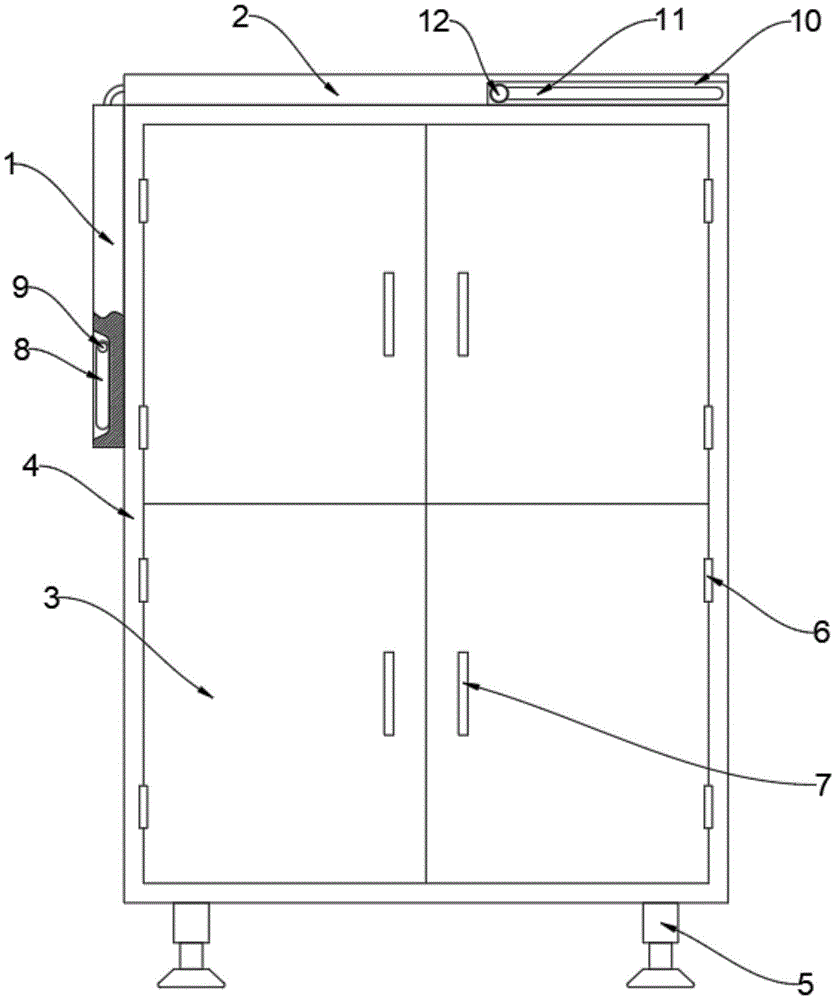
Fig. 1 is a schematic view of the overall external structure of the present invention;
FIG. 2 is a schematic view of the overall internal structure of the present invention;
fig. 3 is a side view of the utility model in its entirety;
fig. 4 is a schematic structural diagram of the rectangular block of the present invention.
In the figure: 1. a bedplate A; 2. a bedplate B; 3. a cabinet door; 4. a cabinet body; 5. supporting legs; 6. a hinge; 7. a door handle; 8. a handle; 9. a rotating shaft; 10. a strip plate; 11. a chute; 12. a slider; 13. a partition plate; 14. a sterilizing lamp; 15. a drawer; 16. a groove; 17. a rectangular block; 18. opening the gap; 19. and a limiting block.
Detailed Description
The technical solutions in the embodiments of the present invention will be described clearly and completely with reference to the accompanying drawings in the embodiments of the present invention, and it is obvious that the described embodiments are only some embodiments of the present invention, not all embodiments.
Referring to fig. 1 to 4, the present invention provides an embodiment: the utility model provides a medical instrument holds device, including the cabinet body 4, the preceding terminal surface of cabinet body 4 is provided with four cabinet doors 3, cabinet door 3 keeps away from the preceding terminal surface of cabinet body 4 one side and all installs door handle 7, platen B2 is installed to the up end of cabinet body 4, the one end fixed mounting of cabinet body 4 top has strip shaped plate 10, the centre of strip shaped plate 10 is provided with spout 11, platen B2 is close to the fixed surface of strip shaped plate 10 one side and has slider 12, platen B2 is kept away from the one end of strip shaped plate 10 and is installed platen A1, platen A1 keeps away from the upper surface of platen B2 one end and is provided with recess 16, the inside of recess 16 is provided with handle 8, nine stopper 19 are all installed to the both sides of cabinet body 4 inner wall, stopper 19's top is provided with baffle 13, the inside bottom of cabinet body 4 is.
Further, hinge 6 is fixedly mounted at the upper end and the lower end of the cabinet door 3 close to one side of the cabinet body 4, and opening and closing are facilitated.
Furthermore, supporting legs 5 are all installed at four end angles of the bottom end face of the cabinet body 4, so that the cabinet body 4 is more stable.
Further, the top card of slider 12 is in the inside of lath 10, avoids platen B to drop from the cabinet body 4.
Further, four end corners of the outer rear end face of the cabinet body 4 are fixedly provided with rectangular blocks 17, the middle of each rectangular block 17 is provided with a notch 18, and the cabinet body 4 can be hung on a wall as required.
Further, the top end of the handle 8 is fixedly connected with the bedplate A1 through a rotating shaft 9.
The working principle is as follows: when the cabinet is used, the cabinet body 4 is placed at a proper position, the power is switched on, the supporting legs 5 support the cabinet body 4, the cabinet door 3 is opened through the door handle 7, the drawer 15 is pulled open, the partition plate 13 which is not used temporarily is pulled out from the position between the limiting blocks 19 to be placed in the drawer 15 to be stored, the drawer 15 is pushed back to the inside of the cabinet body 4, the cabinet door 3 is closed, the medical equipment in the cabinet body 4 is disinfected through the disinfection lamp 14, the bedplate A1 and the bedplate B2 are kept horizontal by pulling the rotating shaft 9, the bedplate A1 is pushed towards the bedplate B2, and the table top is enlarged
It is obvious to a person skilled in the art that the invention is not restricted to details of the above-described exemplary embodiments, but that it can be implemented in other specific forms without departing from the spirit or essential characteristics of the invention. The present embodiments are therefore to be considered in all respects as illustrative and not restrictive, the scope of the invention being indicated by the appended claims rather than by the foregoing description, and all changes which come within the meaning and range of equivalency of the claims are therefore intended to be embraced therein. Any reference sign in a claim should not be construed as limiting the claim concerned.

Claims (6)

1.一种医疗器械盛放装置,包括柜体(4),其特征在于:所述柜体(4)的前端面设置有四个柜门(3),所述柜门(3)远离柜体(4)一侧的前端面均安装有门把手(7),所述柜体(4)的上端面安装有台板B(2),所述柜体(4)上方的一端固定安装有条形板(10),所述条形板(10)的中间设置有滑槽(11),所述台板B(2)靠近条形板(10)一侧的外表面固定安装有滑块(12),所述台板B(2)远离条形板(10)的一端安装有台板A(1),所述台板A(1)远离台板B(2)一端的上表面设置有凹槽(16),所述凹槽(16)的内部设置有拉手(8),所述柜体(4)内壁的两侧均安装有九个限位块(19),所述限位块(19)的上方设置有隔板(13),所述柜体(4)内部的底端设置有抽屉(15),所述柜体(4)内部的后端面设置有两个消毒灯(14)。1. A medical device containing device, comprising a cabinet body (4), characterized in that: the front end surface of the cabinet body (4) is provided with four cabinet doors (3), and the cabinet doors (3) are far away from the cabinet A door handle (7) is installed on the front end surface of one side of the cabinet body (4), a table board B (2) is installed on the upper end surface of the cabinet body (4), and a top end of the cabinet body (4) is fixedly installed with a A strip-shaped plate (10), wherein a chute (11) is provided in the middle of the strip-shaped plate (10), and a slider is fixedly installed on the outer surface of the platen B (2) close to the side of the strip-shaped plate (10) (12), a platen A(1) is installed on the end of the platen B(2) away from the strip plate (10), and the platen A(1) is installed on the upper surface of the end away from the platen B(2). There is a groove (16), a handle (8) is arranged inside the groove (16), and nine limit blocks (19) are installed on both sides of the inner wall of the cabinet (4). A partition (13) is arranged above the block (19), a drawer (15) is arranged at the bottom end of the inside of the cabinet (4), and two disinfection lamps ( 14). 2.根据权利要求1所述的一种医疗器械盛放装置,其特征在于:所述柜门(3)靠近柜体(4)一侧的上下端均固定安装有合页(6)。2 . The medical device containing device according to claim 1 , wherein the upper and lower ends of the cabinet door ( 3 ) close to the cabinet body ( 4 ) are fixedly installed with hinges ( 6 ). 3 . 3.根据权利要求1所述的一种医疗器械盛放装置,其特征在于:所述柜体(4)底端面的四个端角均安装有支撑脚(5)。3 . The medical device containing device according to claim 1 , wherein the four end corners of the bottom end surface of the cabinet body ( 4 ) are provided with supporting feet ( 5 ). 4 . 4.根据权利要求1所述的一种医疗器械盛放装置,其特征在于:所述滑块(12)的顶端卡在条形板(10)的内部。4 . The medical device containing device according to claim 1 , wherein the top end of the slider ( 12 ) is clamped inside the strip plate ( 10 ). 5 . 5.根据权利要求1所述的一种医疗器械盛放装置,其特征在于:所述柜体(4)外部后端面的四个端角均固定安装有矩形块(17),所述矩形块(17)的中间设置有豁口(18)。5. A medical device containing device according to claim 1, characterized in that: rectangular blocks (17) are fixedly installed at four corners of the outer rear end surface of the cabinet body (4), and the rectangular blocks A gap (18) is provided in the middle of (17). 6.根据权利要求1所述的一种医疗器械盛放装置,其特征在于:所述拉手(8)的顶端通过转轴(9)与台板A(1)固定连接。6 . The medical device containing device according to claim 1 , wherein the top end of the handle ( 8 ) is fixedly connected to the platen A ( 1 ) through a rotating shaft ( 9 ). 7 .
CN202020480931.7U 2020-04-05 2020-04-05 Medical instrument holds device Expired - Fee Related CN212913378U (en)

Priority Applications (1)

Application Number Priority Date Filing Date Title
CN202020480931.7U CN212913378U (en) 2020-04-05 2020-04-05 Medical instrument holds device

Applications Claiming Priority (1)

Application Number Priority Date Filing Date Title
CN202020480931.7U CN212913378U (en) 2020-04-05 2020-04-05 Medical instrument holds device

Publications (1)

Publication Number Publication Date
CN212913378U true CN212913378U (en) 2021-04-09

Family

ID=75297292

Family Applications (1)

Application Number Title Priority Date Filing Date
CN202020480931.7U Expired - Fee Related CN212913378U (en) 2020-04-05 2020-04-05 Medical instrument holds device

Country Status (1)

Country Link
CN (1) CN212913378U (en)

Similar Documents

Publication Publication Date Title
CN204542372U (en) A kind of Cardiological diagnosis and treatment table
CN201257068Y (en) Medical box for field operations
CN206006515U (en) A kind of sterilized draining bedside cupboard
CN213641197U (en) Clinical auxiliary treatment device of department of general surgery of children
CN214908182U (en) Clinical anesthesia branch of academic or vocational study is with portable medical case of diagnosing
CN213489924U (en) Isolation nursing bed for infectious department
CN213759583U (en) Medical instrument containing box is used in operating room nursing
CN213344887U (en) Folding bedside cupboard of accompanying and attending to with disinfection function
CN210611537U (en) Intelligent medical bedside cabinet based on PLC
CN211214940U (en) A antidrip formula medicine feeding device that falls for dermatology
CN209847707U (en) Multifunctional nursing cabinet
CN219428641U (en) An internally adjustable basket
CN209332589U (en) A kind of multifunctional portable medical equipment box
CN217524311U (en) Multifunctional bedside cabinet suitable for guardianship ward
CN215915333U (en) Novel rehabilitation nursing bed for clinical nursing
CN213911586U (en) Degassing unit convenient to adjust
CN206350604U (en) A kind of patient's multifunction bedside cabinet
CN215425127U (en) Medical instrument containing box is used in operating room nursing
CN210384039U (en) A retractable medical device storage and disinfection device
CN220070096U (en) Dental chair tray
CN220212356U (en) Bedside table for nursing
CN220530043U (en) Multifunctional ultrasound probe fixing device
CN211131381U (en) Bedside medical cabinet for gynecological minimally invasive surgery
CN215193367U (en) Support is used in operating room nursing
CN214208958U (en) Disinfection cabinet convenient to medical equipment of medical oncology takes fast

Legal Events

Date Code Title Description
GR01 Patent grant
GR01 Patent grant
CF01 Termination of patent right due to non-payment of annual fee

Granted publication date: 20210409