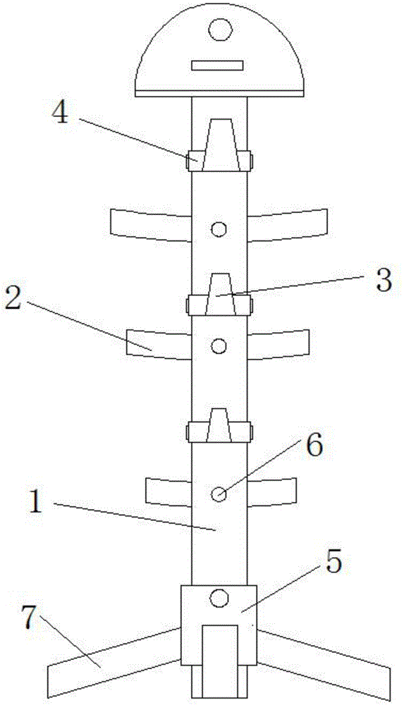
DIY fish bone hat rack
Technical Field
The utility model relates to a hat rack technical field specifically is a DIY fish bone hat rack.
Background
The hat and coat stand is a common small furniture article in home life, can be used for hanging and placing articles such as clothes, hats, backpacks and the like no matter in a living room or a bedroom, can well help people to arrange clothes, is convenient for home life, can improve the space utilization rate of a room and keep the room clean, and therefore the hat and coat stand can improve the overall effect of home space decoration.
However, the existing hatrack still has some disadvantages when in use, for example, the use space is small, so that the articles are less in placement, the structure of the hatrack cannot be adjusted, and the hatrack is not convenient to detach when not in use, so that the utilization rate of the hatrack is reduced, and therefore, the DIY fishbone hatrack is provided, so that the problems provided in the prior art are solved.
SUMMERY OF THE UTILITY MODEL
An object of the utility model is to provide a DIY fish bone hat rack to solve the hat rack usage space ratio that the above-mentioned background art provided and cause article to place less, and can not adjust the structure of hat rack, be not convenient for dismantle the hat rack when not using, thereby reduced the rate of utilization problem of hat rack.
In order to achieve the above object, the utility model provides a following technical scheme: the utility model provides a DIY fish bone hat rack, includes skeleton bracing piece, first connecting sleeve, second connecting sleeve, arc connecting rod, oblique connecting rod and fixed connection round pin, the upper portion of skeleton bracing piece is connected with first connecting sleeve, and first connecting sleeve's upper portion fixedly connected with oblique connecting rod, the middle part of skeleton bracing piece is equipped with square mounting hole, the internal connection of square mounting hole has the arc connecting rod, the upper portion of skeleton bracing piece is equipped with round pin axle mounting hole, the internal connection of round pin axle mounting hole has the fixed connection round pin, the sub-unit connection of skeleton bracing piece has the second connecting sleeve, and the upside fixedly connected with bottom dead lever of second connecting sleeve.
Preferably, the framework supporting rod can form a detachable structure with the first connecting sleeve and the second connecting sleeve through the fixed connecting pin, pin shaft mounting holes are formed in the upper portions of the first connecting sleeve and the second connecting sleeve, and the first connecting sleeve and the second connecting sleeve can be fixed to the upper portion of the framework supporting rod through the matching of the fixed connecting pin and the pin shaft mounting holes.
Preferably, the square mounting hole is connected with the arc-shaped connecting rod through a fixed connecting pin, the width of the square mounting hole is the same as that of the arc-shaped connecting rod, and the arc-shaped connecting rod can be mounted inside the square mounting hole.
Preferably, the second connecting sleeve is connected with the bottom fixing rod through a screw, the first connecting sleeve is connected with the inclined connecting rod through a screw, and the bottom fixing rod can be fixed to the upper portion of the second connecting sleeve through screw connection.
Preferably, the middle part of the arc-shaped connecting rod is provided with a pin shaft mounting hole, and the arc-shaped connecting rod can be fixed inside the framework supporting rod through the matching of the pin shaft mounting hole and the fixed connecting pin.
Preferably, the inner diameter of the first connecting sleeve and the second connecting sleeve is larger than the outer diameter of the framework supporting rod, so that the first connecting sleeve and the second connecting sleeve can move up and down along the framework supporting rod.
Compared with the prior art, the beneficial effects of the utility model are that:
through the fixed connection round pin and the cooperation of round pin axle mounting hole, can fix arc connecting rod and oblique connecting rod, and can improve the support intensity of arc connecting rod and oblique connecting rod, utilize arc connecting rod and oblique connecting rod can hang the clothing simultaneously, and increased the usage space of hat rack, can hang more clothes and article, utilize the fixed connection round pin to connect the position that can also be convenient for adjust arc connecting rod and oblique connecting rod to hat rack's flexibility has been improved, the utility model has the characteristics of simple structure, simple to operate.
Drawings
FIG. 1 is a schematic view of the overall structure of the present invention;
FIG. 2 is a schematic view of the overall left-side view structure of the present invention;
FIG. 3 is a schematic view of the framework support rod of the present invention;
fig. 4 is a left side view structure diagram of the framework support rod of the present invention.
In the figure: 1. a framework support bar; 2. an arc-shaped connecting rod; 3. an oblique connecting rod; 4. a first connecting sleeve; 5. a second connecting sleeve; 6. a fixed connecting pin; 7. a bottom fixing rod; 8. a pin shaft mounting hole; 9. and (5) square mounting holes.
Detailed Description
The technical solutions in the embodiments of the present invention will be described clearly and completely with reference to the accompanying drawings in the embodiments of the present invention, and it is obvious that the described embodiments are only some embodiments of the present invention, not all embodiments. Based on the embodiments in the present invention, all other embodiments obtained by a person skilled in the art without creative work belong to the protection scope of the present invention.
Referring to fig. 1-4, the present invention provides a technical solution: a DIY fish bone hat rack comprises a framework supporting rod 1, a first connecting sleeve 4, a second connecting sleeve 5, an arc-shaped connecting rod 2, a diagonal connecting rod 3 and a fixed connecting pin 6, wherein the upper part of the framework supporting rod 1 is connected with the first connecting sleeve 4, the first connecting sleeve 4 has the function of fixing the diagonal connecting rod 3, the upper part of the first connecting sleeve 4 is fixedly connected with the diagonal connecting rod 3, the middle part of the framework supporting rod 1 is provided with a square mounting hole 9, the arc-shaped connecting rod 2 can be mounted in the square mounting hole 9, the arc-shaped connecting rod 2 is connected in the square mounting hole 9, the upper part of the framework supporting rod 1 is provided with a pin shaft mounting hole 8, the inside of the pin shaft mounting hole 8 is connected with the fixed connecting pin 6, the first connecting sleeve 4 and the second connecting sleeve 5 can be fixed by the fixed connecting pin 6, the lower part of the framework supporting rod 1 is connected with the second connecting sleeve 5, and the upside fixedly connected with bottom dead lever 7 of second connecting sleeve 5, bottom dead lever 7 can improve the stability of skeleton bracing piece 1.
The framework supporting rod 1 can form a dismounting structure with the first connecting sleeve 4 and the second connecting sleeve 5 through the fixed connecting pin 6, the upper portions of the first connecting sleeve 4 and the second connecting sleeve 5 are respectively provided with the pin shaft mounting hole 8, and the first connecting sleeve 4 and the second connecting sleeve 5 can be fixed on the upper portion of the framework supporting rod 1 by matching the fixed connecting pin 6 with the pin shaft mounting hole 8.
Square mounting hole 9 is connected with arc connecting rod 2 through fixed connection round pin 6, the width of square mounting hole 9 is the same with arc connecting rod 2's width, can install arc connecting rod 2 in the inside of square mounting hole 9.
The second connecting sleeve 5 is connected with the bottom fixing rod 7 through a screw, the first connecting sleeve 4 is connected with the inclined connecting rod 3 through a screw, and the bottom fixing rod 7 can be fixed on the upper portion of the second connecting sleeve 5 through screw connection.
The middle part of the arc-shaped connecting rod 2 is provided with a pin shaft mounting hole 8, and the arc-shaped connecting rod 2 can be fixed inside the framework supporting rod 1 by matching the pin shaft mounting hole 8 with the fixed connecting pin 6.
The inner diameter of the first connecting sleeve 4 and the second connecting sleeve 5 is larger than the outer diameter of the framework supporting rod 1, so that the first connecting sleeve 4 and the second connecting sleeve 5 can move up and down along the framework supporting rod 1.
The working principle is as follows: when the fishbone hat rack is used, the oblique connecting rod 3 and the bottom fixing rod 7 can be fixed on the upper parts of the first connecting sleeve 4 and the second connecting sleeve 5 by using screw connection, the first connecting sleeve 4 and the second connecting sleeve 5 are arranged on the outer side of the framework supporting rod 1, the first connecting sleeve 4 and the second connecting sleeve 5 are fixed by using the fixed connecting pin 6 and the pin shaft mounting hole 8 to be matched, meanwhile, the arc-shaped connecting rod 2 can be fixed in the square mounting hole 9 on the upper part of the framework supporting rod 1 by using the fixed connecting pin 6, the use space of the hat rack can be enlarged by using the arc-shaped connecting rod 2 and the oblique connecting rod 3, the hat rack can be used for hanging more clothes and articles, meanwhile, the stability of the framework supporting rod 1 can be improved by using the bottom fixing rod 7, and the hat rack has the characteristics of simple structure and convenient installation, thereby being the working process of the whole, those not described in detail in this specification are well within the skill of the art.
Although the present invention has been described in detail with reference to the foregoing embodiments, it will be apparent to those skilled in the art that modifications may be made to the embodiments or portions thereof without departing from the spirit and scope of the invention.