CN212896326U - Square pile enhancement mode mosaic structure - Google Patents
Square pile enhancement mode mosaic structure Download PDFInfo
- Publication number
- CN212896326U CN212896326U CN202021593800.6U CN202021593800U CN212896326U CN 212896326 U CN212896326 U CN 212896326U CN 202021593800 U CN202021593800 U CN 202021593800U CN 212896326 U CN212896326 U CN 212896326U
- Authority
- CN
- China
- Prior art keywords
- square pile
- fixed
- main body
- fixedly connected
- threaded
- Prior art date
- Legal status (The legal status is an assumption and is not a legal conclusion. Google has not performed a legal analysis and makes no representation as to the accuracy of the status listed.)
- Active
Links
Images


Landscapes
- Piles And Underground Anchors (AREA)
Abstract
The utility model belongs to the field of square piles, in particular to a square pile reinforced splicing structure, which aims at the problems of complex operation, low connection strength and inconvenient use of the prior square pile during splicing, and provides a proposal that comprises a first square pile main body and a second square pile main body, one side of the first square pile main body is fixedly connected with a fixed seat, a fixed cavity is arranged on the fixed seat, one side of the second square pile main body is fixedly connected with a connecting column, one end of the connecting column extends into the fixed cavity, the top of the fixed seat is connected with a driving shaft by screw threads, a sliding plate is connected in the fixed cavity in a sliding way, the utility model has reasonable structure and simple operation, two clamping pins can be respectively clamped with two clamping grooves by rotating the driving shaft downwards, the connecting column is fixed, thereby the first square pile main body and the second square pile main body can be spliced quickly, and the connection strength is high.
Description
Technical Field
The utility model relates to a square pile technical field especially relates to a square pile enhancement mode mosaic structure.
Background
The square pile is a concrete prefabricated component and mainly comprises a square pile body, an end plate, a steel ferrule and the like.
The existing square pile is complex to operate and not high in connection strength and inconvenient to use when being spliced, so that a square pile reinforced splicing structure is provided for solving the problems.
SUMMERY OF THE UTILITY MODEL
The utility model aims at solving the shortcomings of the prior art that the operation is complicated, the connection strength is not high and the use is inconvenient when the existing square pile is spliced, and providing a square pile enhanced splicing structure.
In order to achieve the above purpose, the utility model adopts the following technical scheme:
a square pile enhanced splicing structure comprises a first square pile main body and a second square pile main body, wherein one side of the first square pile main body is fixedly connected with a fixed seat, a fixed cavity is arranged on the fixed seat, one side of the second square pile main body is fixedly connected with a connecting column, one end of the connecting column extends into the fixed cavity, the top of the fixed seat is in threaded connection with a driving shaft, a sliding plate is in sliding connection in the fixed cavity, the top end of the driving shaft is fixedly connected with a knob, the bottom end of the driving shaft extends into the fixed cavity and is rotationally connected with the top of the sliding plate, the bottom of the sliding plate is symmetrically and fixedly connected with two fixed columns, a ball screw is rotationally connected to the inner wall of the bottom of the fixed cavity, a screw nut is in threaded connection with the ball screw, and the bottom ends of, the ball screw is connected with a threaded shaft in a transmission mode, the bottom end of the threaded shaft is connected with the inner wall of the bottom of the fixed cavity in a rotating mode, a threaded seat is connected to the threaded shaft in a threaded mode, clamping pins are fixedly connected to the top of the threaded seat and the bottom of the sliding plate respectively, clamping grooves are formed in the top of the connecting column and the bottom of the connecting column respectively, one ends, close to each other, of the two clamping pins extend into the two clamping grooves respectively and are clamped with the two clamping grooves respectively, the two clamping pins can be clamped with the two clamping grooves respectively when the driving shaft is rotated downwards, the connecting column is fixed, and therefore the first square pile body and the second square pile body can be spliced quickly, and the connecting strength is high.
Preferably, the fixed cavity internal fixation is connected with the locating plate, the constant head tank has been seted up to one side of locating plate, the one end of spliced pole extends to in the constant head tank and laminates mutually with one side inner wall of constant head tank, screw nut's both sides respectively with one side inner wall of fixed cavity and one side sliding connection of locating plate, when laminating mutually with one side inner wall of constant head tank through the one end of spliced pole, the draw-in groove on the spliced pole just corresponds with the bayonet lock, can fix a position the spliced pole fast like this, the convenient concatenation.
Preferably, the inner walls of the two sides of the fixed cavity are both provided with sliding grooves, the two sides of the sliding plate are respectively in sliding connection with the inner wall of one side, away from the two sliding grooves, of the sliding plate, and the sliding grooves can enable the sliding plate to move smoothly.
Preferably, ball and the epaxial all fixed cover of screw are equipped with the belt pulley, and transmission connection has same drive belt on two belt pulleys, through two belt pulleys and a drive belt, can make the screw thread axle rotate in step, conveniently splices.
Preferably, sliding connection has the gag lever post on the opposite side inner wall of fixed cavity, the one end of gag lever post and one side fixed connection of screw thread seat, the gag lever post can carry on spacingly to the screw thread seat, makes the screw thread seat can only longitudinal movement, can not take place the offset.
The utility model discloses in, a square pile enhancement mode mosaic structure, owing to set up the drive shaft, can make the sliding plate move down through rotating the drive shaft downwards, the sliding plate can make screw nut remove through the fixed column, thereby can make ball rotate, ball rotates and can make the screw thread axle rotate through two belt pulleys and drive belt, the screw thread axle rotates and can make screw thread seat rebound, at this moment sliding plate and screw thread seat can make two bayonet locks move to the direction that is close to each other simultaneously, thereby can clamp with two bayonet grooves respectively mutually, just so can fix the spliced pole, the operation is thus simple, can splice first square pile main part and second square pile main part fast, and joint strength is high.
Due to the fact that the positioning plate is arranged and the positioning groove is formed in the positioning plate, when one end of the connecting column is attached to the inner wall of one side of the positioning groove, the clamping groove in the connecting column is just corresponding to the clamping pin, the connecting column can be rapidly positioned, and splicing is convenient.
The utility model discloses rational in infrastructure, easy operation clamps with two slots respectively mutually through two bayonet locks when the drive shaft just can be rotated downwards, fixes the spliced pole to can splice first side stake main part and second side stake main part fast, and joint strength is high.
Drawings
Fig. 1 is a schematic view of a local three-dimensional structure of a square pile reinforced splicing structure provided by the present invention;
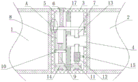
fig. 2 is a schematic main sectional structure view of a square pile reinforced splicing structure provided by the present invention;
fig. 3 is the utility model provides a square pile enhancement mode mosaic structure's a part enlargies the structure sketch map.
In the figure: 1 first square pile main part, 2 second square pile main parts, 3 fixing bases, 4 connecting columns, 5 fixing cavities, 6 driving shafts, 7 sliding plates, 8 fixing columns, 9 ball screws, 10 screw nuts, 11 threaded shafts, 12 threaded seats, 13 clamping pins, 14 belt pulleys, 15 limiting rods, 16 sliding grooves and 17 positioning plates.
Detailed Description
The technical solutions in the embodiments of the present invention will be described clearly and completely with reference to the accompanying drawings in the embodiments of the present invention, and it is obvious that the described embodiments are only some embodiments of the present invention, not all embodiments.
Example one
Referring to fig. 1-3, a square pile enhanced splicing structure comprises a first square pile main body 1 and a second square pile main body 2, one side of the first square pile main body 1 is fixedly connected with a fixed seat 3, a fixed chamber 5 is arranged on the fixed seat 3, one side of the second square pile main body 2 is fixedly connected with a connecting column 4, one end of the connecting column 4 extends into the fixed chamber 5, the top of the fixed seat 3 is in threaded connection with a driving shaft 6, a sliding plate 7 is slidably connected in the fixed chamber 5, the top of the driving shaft 6 is fixedly connected with a knob, the bottom of the driving shaft 6 extends into the fixed chamber 5 and is rotatably connected with the top of the sliding plate 7, the bottom of the sliding plate 7 is symmetrically and fixedly connected with two fixed columns 8, a ball screw 9 is rotatably connected on the inner wall of the bottom of the fixed chamber 5, a screw nut 10 is in threaded connection with the ball, the ball screw 9 is in transmission connection with a threaded shaft 11, the bottom end of the threaded shaft 11 is rotationally connected with the inner wall of the bottom of the fixed cavity 5, the threaded shaft 11 is in threaded connection with a threaded seat 12, the top of the threaded seat 12 and the bottom of the sliding plate 7 are both fixedly connected with clamping pins 13, the top and the bottom of the connecting column 4 are both provided with clamping grooves, one ends of the two clamping pins 13, which are close to each other, respectively extend into the two clamping grooves and are respectively clamped with the two clamping grooves, the two clamping pins 13 can be respectively clamped with the two clamping grooves by downwards rotating the driving shaft 6 to fix the connecting column 4, so that the first square pile body 1 and the second square pile body 2 can be quickly spliced, the connection strength is high, due to the arrangement of the driving shaft 6, the sliding plate 7 can downwards move by downwards rotating the driving shaft 6, and the sliding plate 7 can move the screw nut 10, thereby enabling the ball screw 9 to rotate, the ball screw 9 can rotate to enable the threaded shaft 11 to rotate through the two belt pulleys 14 and the transmission belt, the threaded shaft 11 rotates to enable the threaded seat 12 to move upwards, at the same time, the sliding plate 7 and the threaded seat 12 can simultaneously enable the two clamping pins 13 to move towards the directions close to each other, thereby being respectively clamped with the two clamping grooves, so that the connecting column 4 can be fixed, the operation is simple, the first square pile main body 1 and the second square pile main body 2 can be quickly spliced, the connection strength is high, due to the arrangement of the positioning plate 17, the positioning groove is arranged on the positioning plate 17, when one end of the connecting column 4 is attached to one side inner wall of the positioning groove, the clamping groove on the connecting column 4 just corresponds to the clamping pin 13, so that the connecting column 4 can be quickly positioned, the splicing is convenient, the utility model has reasonable, two bayonet locks 13 clamp with two draw-in grooves respectively when just can through the downward rotation drive shaft 6, fix spliced pole 4 to can splice first side stake main part 1 and second side stake main part 2 fast, and joint strength is high.
Example two
The utility model discloses in, fixedly connected with locating plate 17 in the fixed cavity 5, the constant head tank has been seted up to one side of locating plate 17, the one end of spliced pole 4 extends to in the constant head tank and laminate mutually with one side inner wall of constant head tank, screw nut 10's both sides respectively with one side inner wall of fixed cavity 5 and one side sliding connection of locating plate 17, when laminating mutually with one side inner wall of constant head tank through the one end of spliced pole 4, draw-in groove on the spliced pole 4 just corresponds with bayonet lock 13, can fix a position spliced pole 4 fast like this, the convenient concatenation.
The utility model discloses in, all seted up spout 16 on the both sides inner wall of fixed cavity 5, the both sides of sliding plate 7 respectively with the one side inner wall sliding connection that two spout 16 kept away from each other, spout 16 can make the more smooth-going removal of sliding plate 7.
The utility model discloses in, all fixed cover is equipped with belt pulley 14 on ball 9 and the threaded shaft 11, and the transmission is connected with same drive belt on two belt pulleys 14, through two belt pulleys 14 and a drive belt, can make threaded shaft 11 rotate in step, conveniently splices.
The utility model discloses in, sliding connection has gag lever post 15 on the opposite side inner wall of fixed cavity 5, and one side fixed connection of one end and screw thread seat 12 of gag lever post 15, gag lever post 15 can carry on spacingly to screw thread seat 12, make screw thread seat 12 can only longitudinal movement, can not take place the offset.
In the utility model, when the first square pile body 1 and the second square pile body 2 are needed to be spliced, one end of the connecting column 4 is firstly inserted into the fixed cavity 5, when one end of the connecting column 4 is attached to one side inner wall of the positioning groove, the clamping groove on the connecting column 4 just corresponds to the clamping pin 13, then the driving shaft 6 is rotated downwards, the driving shaft 6 can make the sliding plate 7 move downwards, the sliding plate 7 can drive the screw nut 10 to move downwards through the two fixing columns 8 while moving downwards, because the screw nut 10 is in threaded connection with the ball screw 9, and the transmission of the two has reversibility, the screw nut 10 can make the ball screw 9 rotate, the ball screw 9 can make the threaded shaft 11 rotate through the two belt pulleys 14 and the transmission belt, the threaded shaft 11 can make the screw base 12 move upwards, at the moment, the sliding plate 7 and the threaded base 12 can make the two clamping pins 13 move towards the direction close to each other simultaneously, thereby can clamp with two draw-in grooves respectively mutually, just so can fix spliced pole 4, easy operation can splice first side stake main part 1 and second side stake main part 2 fast, and joint strength is high.
The above, only be the concrete implementation of the preferred embodiment of the present invention, but the protection scope of the present invention is not limited thereto, and any person skilled in the art is in the technical scope of the present invention, according to the technical solution of the present invention and the utility model, the concept of which is equivalent to replace or change, should be covered within the protection scope of the present invention.
Claims (5)
1. A square pile reinforced splicing structure comprises a first square pile main body (1) and a second square pile main body (2), and is characterized in that a fixed seat (3) is fixedly connected to one side of the first square pile main body (1), a fixed cavity (5) is arranged on the fixed seat (3), a connecting column (4) is fixedly connected to one side of the second square pile main body (2), one end of the connecting column (4) extends into the fixed cavity (5), a driving shaft (6) is in threaded connection with the top of the fixed seat (3), a sliding plate (7) is in sliding connection with the fixed cavity (5), a knob is fixedly connected to the top end of the driving shaft (6), the bottom end of the driving shaft (6) extends into the fixed cavity (5) and is rotatably connected with the top of the sliding plate (7), two fixed columns (8) are symmetrically and fixedly connected to the bottom of the sliding plate (7), the improved structure of the clamping device is characterized in that a ball screw (9) is rotatably connected to the inner wall of the bottom of the fixed cavity (5), a screw nut (10) is connected to the ball screw (9) in a threaded manner, the bottom ends of two fixed columns (8) are fixedly connected with the top of the screw nut (10), a threaded shaft (11) is connected to the ball screw (9) in a transmission manner, the bottom end of the threaded shaft (11) is rotatably connected with the inner wall of the bottom of the fixed cavity (5), a threaded base (12) is connected to the threaded shaft (11) in a threaded manner, clamping grooves are formed in the top and the bottom of the connecting column (4), and one ends, close to each other, of the two clamping grooves (13) extend into the two clamping grooves respectively and are clamped with the two clamping grooves respectively.
2. The square pile reinforced splicing structure according to claim 1, wherein a positioning plate (17) is fixedly connected in the fixing chamber (5), a positioning groove is formed in one side of the positioning plate (17), one end of the connecting column (4) extends into the positioning groove and is attached to one side inner wall of the positioning groove, and two sides of the screw nut (10) are respectively and slidably connected with one side inner wall of the fixing chamber (5) and one side of the positioning plate (17).
3. A square pile reinforced splicing structure according to claim 1, wherein sliding grooves (16) are formed in the inner walls of the two sides of the fixed chamber (5), and the two sides of the sliding plate (7) are slidably connected with the inner wall of the side where the two sliding grooves (16) are far away from each other.
4. The square pile reinforced splicing structure of claim 1, wherein a belt pulley (14) is fixedly sleeved on each of the ball screw (9) and the threaded shaft (11), and the two belt pulleys (14) are in transmission connection with the same transmission belt.
5. A square pile reinforced splicing structure according to claim 1, wherein a limiting rod (15) is slidably connected to the inner wall of the other side of the fixing chamber (5), and one end of the limiting rod (15) is fixedly connected to one side of the threaded seat (12).
Priority Applications (1)
| Application Number | Priority Date | Filing Date | Title |
|---|---|---|---|
| CN202021593800.6U CN212896326U (en) | 2020-08-04 | 2020-08-04 | Square pile enhancement mode mosaic structure |
Applications Claiming Priority (1)
| Application Number | Priority Date | Filing Date | Title |
|---|---|---|---|
| CN202021593800.6U CN212896326U (en) | 2020-08-04 | 2020-08-04 | Square pile enhancement mode mosaic structure |
Publications (1)
| Publication Number | Publication Date |
|---|---|
| CN212896326U true CN212896326U (en) | 2021-04-06 |
Family
ID=75235271
Family Applications (1)
| Application Number | Title | Priority Date | Filing Date |
|---|---|---|---|
| CN202021593800.6U Active CN212896326U (en) | 2020-08-04 | 2020-08-04 | Square pile enhancement mode mosaic structure |
Country Status (1)
| Country | Link |
|---|---|
| CN (1) | CN212896326U (en) |
-
2020
- 2020-08-04 CN CN202021593800.6U patent/CN212896326U/en active Active
Similar Documents
| Publication | Publication Date | Title |
|---|---|---|
| CN113389276A (en) | Light-duty assembled steel construction building | |
| CN112815915A (en) | Portable surveying and mapping tower ruler device with infrared auxiliary light for geological engineering and use method | |
| CN213898119U (en) | Keel is consolidated to template | |
| CN108756070B (en) | A method to improve the efficiency of building construction | |
| CN211889114U (en) | Basketball stand column drilling machine | |
| CN218843910U (en) | High strength wind resistance electric power iron tower | |
| CN221696790U (en) | A worm gear tooth surface detection fixture | |
| CN116423868B (en) | Laminated plate winding device and method | |
| CN220621141U (en) | Photovoltaic power generation installs built-in fitting auxiliary positioning device | |
| CN219825220U (en) | Stirring is planted stake and is used guide support frame | |
| CN218836798U (en) | Plate machining clamp | |
| CN217180171U (en) | A bar planting sample preparation facilities for bar planting is drawn experimental | |
| CN214173788U (en) | Underground ground sampling device | |
| CN216371380U (en) | Grinding device is used in production of car transmission shaft with rotatory support function | |
| CN212622933U (en) | Layering block and support frame of PCB test fixture | |
| CN204160129U (en) | A kind of load-bearing combination tool of locking pin mechanism | |
| CN215443929U (en) | Anchoring device for horizontal directional drilling machine | |
| CN212292596U (en) | Rotation limiter of tower crane | |
| CN212094824U (en) | Novel optic fibre laser marking machine alignment jig | |
| CN223793584U (en) | Highway bridge foundation pile reinforcing apparatus | |
| CN219992421U (en) | Built-in pile convenient to splice | |
| CN221095862U (en) | A construction engineering template fixing device | |
| CN213682081U (en) | Concrete pipe pile splicing device | |
| CN222517043U (en) | Device for accelerating rabbit cerebral hemorrhage | |
| CN220007197U (en) | Stable glass fiber reinforced plastic pipeline cone grinding equipment |
Legal Events
| Date | Code | Title | Description |
|---|---|---|---|
| GR01 | Patent grant | ||
| GR01 | Patent grant |