CN212886227U - Turnover structure for machining of numerical control metal cutting machine tool - Google Patents
Turnover structure for machining of numerical control metal cutting machine tool Download PDFInfo
- Publication number
- CN212886227U CN212886227U CN202021624982.9U CN202021624982U CN212886227U CN 212886227 U CN212886227 U CN 212886227U CN 202021624982 U CN202021624982 U CN 202021624982U CN 212886227 U CN212886227 U CN 212886227U
- Authority
- CN
- China
- Prior art keywords
- fixedly connected
- numerical control
- cutting machine
- machine tool
- motor
- Prior art date
- Legal status (The legal status is an assumption and is not a legal conclusion. Google has not performed a legal analysis and makes no representation as to the accuracy of the status listed.)
- Active
Links
Images
Abstract
The utility model discloses a flip structure is used in processing of numerical control metal-cutting machine tool, which comprises a base, two supporting seats that the top fixedly connected with symmetry of base set up, two the equal fixedly connected with telescopic cylinder in top of supporting seat, telescopic cylinder's output fixedly connected with telescopic link, telescopic cylinder's one end fixedly connected with mounting panel is kept away from to the telescopic link, one side fixedly connected with motor of telescopic link is kept away from to the mounting panel, the output fixedly connected with axostylus axostyle of motor, the one of motor was kept away from to the axostylus axostyle serves the fixedly connected with fixed plate, be equipped with the rotation chamber on the fixed plate, it is equipped with the threaded rod to rotate the intracavity, the utility model discloses effectually overturn the work.
Description
Technical Field
The utility model relates to a relevant goods field of metal cutting specifically is a flip structure is used in numerical control metal cutting machine processing.
Background
Metal cutting is a material removal additive forming method in metal forming processes, and still accounts for a large proportion of the current mechanical manufacturing. The metal cutting process is the process by which the workpiece and the tool interact. The tool cuts off redundant metal from a workpiece to be machined, and under the premise of controlling productivity and cost, the workpiece obtains geometric accuracy, dimensional accuracy and surface quality which meet the requirements of design and process, and the front and back surfaces of the workpiece are often required to be machined.
However, the existing turning structure for machining the numerical control metal cutting machine tool is poor in stability, complex in structure, high in cost, inconvenient to operate and defective.
SUMMERY OF THE UTILITY MODEL
An object of the utility model is to provide a flip structure is used in numerical control metal cutting machine tool processing to it is relatively poor to propose current flip structure stability for numerical control metal cutting machine tool processing among the above-mentioned background art to solve, and the structure is comparatively complicated, and is with high costs, the inconvenient problem of operation.
In order to achieve the above object, the utility model provides a following technical scheme: a turnover structure for machining of a numerical control metal cutting machine tool comprises a base, wherein the top of the base is fixedly connected with two symmetrically arranged supporting seats, the tops of the two supporting seats are fixedly connected with a telescopic cylinder, the output end of the telescopic cylinder is fixedly connected with a telescopic rod, one end of the telescopic rod, far away from the telescopic cylinder, is fixedly connected with a mounting plate, one side of the mounting plate, far away from the telescopic rod, is fixedly connected with a motor, the output end of the motor is fixedly connected with a shaft rod, one end of the shaft rod, far away from the motor, is fixedly connected with a fixing plate, a rotating cavity is arranged on the fixing plate, a threaded rod is arranged in the rotating cavity, two clamping plates are sleeved on the threaded rod in a threaded manner, threads in the two clamping plate threads are oppositely arranged, one end of the threaded rod is rotatably connected with, the top fixedly connected with mounting box of base, the mounting box top is equipped with the opening, it is equipped with the receiver to slide to insert in the mounting box.
Preferably, the telescopic cylinder is an electric cylinder.
Preferably, the motor is a servo motor.
Preferably, a plurality of anti-skid lines are arranged on the rotating block.
Preferably, one side of each of the two clamping plates opposite to each other is fixedly connected with a rubber plate.
Preferably, a handle is fixedly connected to the outer wall of one side of the storage box.
Compared with the prior art, the beneficial effects of the utility model are that:
this numerical control flip structure for metal cutting machine tool processing, place between two fixed plates through treating the processing work piece, start the telescopic cylinder at supporting seat top afterwards and drive the telescopic link motion, thereby the telescopic link will promote the mounting panel to remove and make the work piece both ends be located between two grip blocks, rotate the commentaries on classics piece afterwards and drive the threaded rod and rotate rotating the intracavity, thereby two grip blocks of installing on the threaded rod at this moment carry out the centre gripping to the work piece and fix in the setting of opposite screw thread, can drive the axostylus axostyle through starter motor and rotate, realize the work piece upset when adding man-hour, the utility model discloses effectual upset to the work piece, it is higher to stabilize the centre gripping nature, has improved.
Drawings
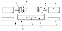
Fig. 1 is a schematic structural view of a turning structure for machining a numerical control metal cutting machine according to the present invention;
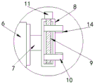
FIG. 2 is an enlarged view of the turning structure for machining of the numerical control metal cutting machine of the present invention at the A position;
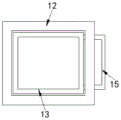
fig. 3 is the utility model discloses a numerical control metal cutting machine processing is with flip structure's inside sketch map of mounting box.
In the figure: 1-base, 2-support base, 3-telescopic cylinder, 4-telescopic rod, 5-mounting plate, 6-motor, 7-shaft rod, 8-fixing plate, 9-threaded rod, 10-clamping plate, 11-rotating block, 12-mounting box, 13-storage box, 14-rubber plate, and 15-handle.
Detailed Description
The technical solutions in the embodiments of the present invention will be described clearly and completely with reference to the accompanying drawings in the embodiments of the present invention, and it is obvious that the described embodiments are only some embodiments of the present invention, not all embodiments.
Referring to fig. 1-3, the present invention provides an embodiment: a turnover structure for machining of a numerical control metal cutting machine tool comprises a base 1, the top of the base 1 is fixedly connected with two symmetrically arranged supporting seats 2, the tops of the two supporting seats 2 are fixedly connected with a telescopic cylinder 3, the output end of the telescopic cylinder 3 is fixedly connected with a telescopic rod 4, one end of the telescopic rod 4 far away from the telescopic cylinder 3 is fixedly connected with a mounting plate 5, one side of the mounting plate 5 far away from the telescopic rod 4 is fixedly connected with a motor 6, the output end of the motor 6 is fixedly connected with a shaft rod 7, one end of the shaft rod 7 far away from the motor 6 is fixedly connected with a fixing plate 8, a rotating cavity is arranged on the fixing plate 8, a threaded rod 9 is arranged in the rotating cavity, two clamping plates 10 are sleeved on the threaded rod 9 in a threaded manner, threads in the threaded ports of the two clamping plates 10 are oppositely arranged, one end of, the top fixedly connected with mounting box 12 of base 1, mounting box 12 top is equipped with the opening, it is equipped with receiver 13 to slide to insert in mounting box 12, specific saying, treat that the processing work piece is placed between two fixed plates 8, the telescopic cylinder 3 that starts 2 tops of supporting seat drives the telescopic link 4 motion afterwards, thereby telescopic link 4 will promote mounting panel 5 and remove and make the work piece both ends be located between two grip blocks 10, it rotates 11 drive threaded rod 9 and rotates at the rotation intracavity afterwards to rotate the piece, thereby two grip blocks 10 that install on threaded rod 9 remove and carry out the centre gripping fixedly at the setting of opposite screw mouth this moment, can drive axostylus axostyle 7 through starter motor 6 and rotate, realize the upset of work piece when adding man-hour.
Further, the telescopic cylinder 3 is an electric cylinder.
Further, the motor 6 is a servo motor.
Furthermore, the rotating block 11 is provided with a plurality of anti-slip lines, so that friction force is increased, and rotation is facilitated.
Further, a rubber plate 14 is fixedly connected to the opposite sides of the two clamping plates 10, so that the buffering force is increased.
Further, fixedly connected with handle 15 on one side outer wall of receiver 13 is convenient for pull receiver 13.
The working principle is as follows: at first will wait to process the work piece and place between two fixed plates 8, start the telescopic cylinder 3 at 2 tops of supporting seat and drive the motion of telescopic link 4 afterwards, thereby telescopic link 4 will promote the 5 removal of mounting panel and make the work piece both ends be located between two grip blocks 10, rotate the piece 11 afterwards and drive threaded rod 9 and rotate at the rotation intracavity, thereby two grip blocks 10 of installing on threaded rod 9 at this moment move in the setting of opposite screw thread and carry out the centre gripping to the work piece fixedly, can drive axostylus axostyle 7 through starter motor 6 and rotate, realize the upset of work piece when adding man-hour.
It is obvious to a person skilled in the art that the invention is not restricted to details of the above-described exemplary embodiments, but that it can be implemented in other specific forms without departing from the spirit or essential characteristics of the invention. The present embodiments are therefore to be considered in all respects as illustrative and not restrictive, the scope of the invention being indicated by the appended claims rather than by the foregoing description, and all changes which come within the meaning and range of equivalency of the claims are therefore intended to be embraced therein. Any reference sign in a claim should not be construed as limiting the claim concerned.
Claims (6)
1. The utility model provides a numerical control metalworking lathe processing is with flip structure, includes base (1), its characterized in that: the top of the base (1) is fixedly connected with two symmetrically arranged supporting seats (2), the tops of the two supporting seats (2) are fixedly connected with a telescopic cylinder (3), the output end of the telescopic cylinder (3) is fixedly connected with a telescopic rod (4), one end of the telescopic rod (4) far away from the telescopic cylinder (3) is fixedly connected with a mounting plate (5), one side of the mounting plate (5) far away from the telescopic rod (4) is fixedly connected with a motor (6), the output end of the motor (6) is fixedly connected with a shaft rod (7), one end of the shaft rod (7) far away from the motor (6) is fixedly connected with a fixed plate (8), a rotating cavity is arranged on the fixed plate (8), a threaded rod (9) is arranged in the rotating cavity, two clamping plates (10) are sleeved on the threaded rod (9), and the threads in the threads of the two clamping plates (10, the one end of threaded rod (9) with rotate the intracavity wall and rotate and be connected, the other end of threaded rod (9) runs through and rotates chamber and fixedly connected with and change piece (11), the top fixedly connected with mounting box (12) of base (1), mounting box (12) top is equipped with the opening, it is equipped with receiver (13) to slide to insert in mounting box (12).
2. The turning structure for numerical control metal cutting machine tool machining according to claim 1, characterized in that: the telescopic cylinder (3) is an electric cylinder.
3. The turning structure for numerical control metal cutting machine tool machining according to claim 1, characterized in that: the motor (6) is a servo motor.
4. The turning structure for numerical control metal cutting machine tool machining according to claim 1, characterized in that: and a plurality of anti-skid lines are arranged on the rotating block (11).
5. The turning structure for numerical control metal cutting machine tool machining according to claim 1, characterized in that: and one opposite side of the two clamping plates (10) is fixedly connected with a rubber plate (14).
6. The turning structure for numerical control metal cutting machine tool machining according to claim 1, characterized in that: the outer wall of one side of the storage box (13) is fixedly connected with a handle (15).
Priority Applications (1)
| Application Number | Priority Date | Filing Date | Title |
|---|---|---|---|
| CN202021624982.9U CN212886227U (en) | 2020-08-07 | 2020-08-07 | Turnover structure for machining of numerical control metal cutting machine tool |
Applications Claiming Priority (1)
| Application Number | Priority Date | Filing Date | Title |
|---|---|---|---|
| CN202021624982.9U CN212886227U (en) | 2020-08-07 | 2020-08-07 | Turnover structure for machining of numerical control metal cutting machine tool |
Publications (1)
| Publication Number | Publication Date |
|---|---|
| CN212886227U true CN212886227U (en) | 2021-04-06 |
Family
ID=75236691
Family Applications (1)
| Application Number | Title | Priority Date | Filing Date |
|---|---|---|---|
| CN202021624982.9U Active CN212886227U (en) | 2020-08-07 | 2020-08-07 | Turnover structure for machining of numerical control metal cutting machine tool |
Country Status (1)
| Country | Link |
|---|---|
| CN (1) | CN212886227U (en) |
Cited By (1)
| Publication number | Priority date | Publication date | Assignee | Title |
|---|---|---|---|---|
| CN116833456A (en) * | 2023-08-30 | 2023-10-03 | 福建祥鑫新能源汽车配件制造有限公司 | Full-automatic double-sided milling deburring device for battery tray |
-
2020
- 2020-08-07 CN CN202021624982.9U patent/CN212886227U/en active Active
Cited By (2)
| Publication number | Priority date | Publication date | Assignee | Title |
|---|---|---|---|---|
| CN116833456A (en) * | 2023-08-30 | 2023-10-03 | 福建祥鑫新能源汽车配件制造有限公司 | Full-automatic double-sided milling deburring device for battery tray |
| CN116833456B (en) * | 2023-08-30 | 2023-11-28 | 福建祥鑫新能源汽车配件制造有限公司 | Full-automatic double-sided milling deburring device for battery tray |
Similar Documents
| Publication | Publication Date | Title |
|---|---|---|
| CN210649580U (en) | Rotary clamping device of numerical control machine tool | |
| CN110919409A (en) | General type CNC precision finishing tool base | |
| CN212886227U (en) | Turnover structure for machining of numerical control metal cutting machine tool | |
| CN213288826U (en) | Horizontal numerical control crankshaft machining equipment | |
| CN210548133U (en) | Vertical turning device for processing inner and outer spoke bottoms of automobile spokes | |
| CN209424586U (en) | A kind of efficient stepped hole machining tool | |
| CN216967382U (en) | Turnover saw blade polishing machine | |
| CN214025205U (en) | Precision finishing is with automatic assembly line | |
| CN213257222U (en) | Numerical control machine tool for machining gearbox shell | |
| CN211759002U (en) | Ball screw precision finishing device | |
| CN209754604U (en) | Clamping device for machine tool machining | |
| CN211465604U (en) | Plate pneumatic clamp for numerical control machining center | |
| CN216542136U (en) | Bearing processing common lathe with internal positioning device | |
| CN203356680U (en) | Milling machine provided with numerical control screen | |
| CN206839762U (en) | Inside and outside shaped part apparatus for automatically removing burr | |
| CN111360302A (en) | Ox hair style is simple and easy five high-efficient numerically controlled fraise machine | |
| CN206898455U (en) | Pipeline R arc millings side special purpose machine tool | |
| CN205996622U (en) | Carving machine with tool magazine device | |
| CN214055031U (en) | Movable bracket for machining automobile seat | |
| CN219901725U (en) | Fixed tooling for machining shaft sleeve type workpiece | |
| CN211939901U (en) | Full-automatic numerical control machine tool die machining center equipment | |
| CN216182802U (en) | 3D printer capable of automatically switching main shafts | |
| CN213969359U (en) | Tapping machine | |
| CN220637459U (en) | Clamping device for machining and polishing mechanical parts | |
| CN215041765U (en) | Aluminum product four-axis engraver |
Legal Events
| Date | Code | Title | Description |
|---|---|---|---|
| GR01 | Patent grant | ||
| GR01 | Patent grant |