CN212884778U - Hot die forging press machine simple to operate - Google Patents
Hot die forging press machine simple to operate Download PDFInfo
- Publication number
- CN212884778U CN212884778U CN202021413159.3U CN202021413159U CN212884778U CN 212884778 U CN212884778 U CN 212884778U CN 202021413159 U CN202021413159 U CN 202021413159U CN 212884778 U CN212884778 U CN 212884778U
- Authority
- CN
- China
- Prior art keywords
- die forging
- forging press
- fixed
- hot die
- workbench
- Prior art date
- Legal status (The legal status is an assumption and is not a legal conclusion. Google has not performed a legal analysis and makes no representation as to the accuracy of the status listed.)
- Active
Links
- 238000005242 forging Methods 0.000 title claims abstract description 44
- 238000007493 shaping process Methods 0.000 claims abstract description 15
- 230000002349 favourable effect Effects 0.000 abstract description 5
- 238000009826 distribution Methods 0.000 abstract description 2
- 238000000926 separation method Methods 0.000 abstract description 2
- 238000004519 manufacturing process Methods 0.000 description 9
- 238000003825 pressing Methods 0.000 description 4
- 230000009286 beneficial effect Effects 0.000 description 3
- 238000000034 method Methods 0.000 description 3
- 238000010276 construction Methods 0.000 description 2
- 230000004075 alteration Effects 0.000 description 1
- 238000009434 installation Methods 0.000 description 1
- 239000000463 material Substances 0.000 description 1
- 239000002184 metal Substances 0.000 description 1
- 238000012986 modification Methods 0.000 description 1
- 230000004048 modification Effects 0.000 description 1
- 238000000465 moulding Methods 0.000 description 1
- 239000011435 rock Substances 0.000 description 1
- 238000006467 substitution reaction Methods 0.000 description 1
Images



Landscapes
- Forging (AREA)
Abstract
The utility model discloses an easy operation's hot die forging press, including hot die forging press body, shaping module, haulage rope and footboard, the upper end fixed mounting of hot die forging press body has the workstation, and the inside of workstation has seted up first movable groove, the inside of workstation is provided with the fixed disk, and the inside of fixed disk has seted up second movable groove, the inside in second movable groove is provided with the fixed block, and the inside of fixed block has seted up the through-hole, the shaping module is installed to the upper end of fixed block, and the lower extreme of shaping module is connected with the upper surface of workstation. This easy operation's hot die forging press, about the rocker longitudinal center line symmetric distribution and with the workstation between constitute revolution mechanic's support column, control the rocker through stepping on the pressure footboard and rotate in the workstation is inside, be favorable to follow-up joint pole and the separation of fixed orifices when changing the forming die piece, shortened the time spent when changing the forming die piece.
Description
Technical Field
The utility model relates to a hot mould forging and pressing technical field specifically is an easy operation's hot mould forging press.
Background
The hot die forging press can produce metal die forging and finished forgings in large batch in the manufacturing industry, has the excellent characteristics of high precision of the forgings, high material utilization rate, high production efficiency and the like, is widely applied to modern forging production, and is indispensable high-precision forging equipment for modern forging production.
Most of the hot die forging presses today have several problems:
firstly, the forming module is inconvenient to replace, and the time consumed when the forming module is replaced is long, so that the production efficiency of the hot die forging press is reduced;
the existing hot die forging press with the part convenient for replacing the forming module is not ideal enough in fixing the forming module, and the forming module is easy to shake in the forging process, so that the production quality of the hot die forging press can be influenced.
We have proposed a hot die forging press which is simple to operate so as to solve the problems set forth above.
SUMMERY OF THE UTILITY MODEL
An object of the utility model is to provide an easy operation's hot die forging press to solve common hot die forging press on the existing market that proposes in the above-mentioned background art, its shaping module with change comparatively inconvenient, the time that consumes when changing the shaping module is longer, the shaping module takes place easily at the forging and pressing in-process simultaneously and rocks, thereby can influence the problem of the production quality of hot die forging press.
In order to achieve the above object, the utility model provides a following technical scheme: a hot die forging press easy to operate comprises a hot die forging press body, a forming module, a traction rope and a pedal, wherein a workbench is fixedly mounted at the upper end of the hot die forging press body, a first movable groove is formed in the workbench, a fixed disc is arranged in the workbench, a second movable groove is formed in the fixed disc, a fixed block is arranged in the second movable groove, a through hole is formed in the fixed block, the forming module is mounted at the upper end of the fixed block, the lower end of the forming module is connected with the upper surface of the workbench, a fixed hole is formed in the lower end of the fixed disc, a sliding groove is formed in the workbench, a spring is arranged in the sliding groove, a clamping rod is arranged at the upper end of the spring and connected with the fixed hole, the bottom of the clamping rod is connected with the traction rope, and the tail end of the traction rope is connected with a rocker, the outer surface fixed mounting of rocker has the support column, and the outer end fixed mounting of rocker has the footboard.
Preferably, a rotating structure is formed between the fixed disc and the workbench, and the diameter of the fixed disc is equal to the length of the fixed block.
Preferably, the wide sides of the fixing blocks are of arc structures, and the through holes are distributed in the fixing blocks at equal angles.
Preferably, be bolted connection between shaping module and the fixed block, and all constitute sliding construction between fixed block and first movable groove and the second movable groove.
Preferably, the cross-sectional shape of joint pole is "Y" shape, and the joint pole passes through to constitute extending structure between spring and the spout.
Preferably, the support columns are symmetrically distributed about the longitudinal center line of the rocker, and a rotating structure is formed between the support columns and the workbench.
Compared with the prior art, the beneficial effects of the utility model are that: the hot die forging press with simple operation,
1. the supporting columns are symmetrically distributed about the longitudinal center line of the rocker and form a rotating structure with the workbench, the rocker is controlled to rotate in the workbench by stepping on and pressing the pedal, so that the separation of the clamping rod and the fixing hole during subsequent module replacement is facilitated, and the time spent during module replacement is shortened;
2. the fixed plate with the diameter equal to the length of the fixed block is beneficial to the subsequent fixed plate to drive the fixed block to rotate in the workbench, so that the subsequent fixed plate is beneficial to the fixation in the workbench, and the fixed block with the arc-shaped wide edge can reduce the friction force between the fixed block and the workbench to the maximum extent, so that the fixed plate can rotate in the workbench more easily;
3. and be bolted connection's shaping module between the fixed block, be favorable to follow-up shaping module's change, reduced the time of changing the shaping module and spending, improved the production efficiency of hot die forging press, and the joint pole of the cross-sectional shape for "Y" shape can carry out the block to two fixed orificess that the fixed disk lower extreme was seted up simultaneously, is favorable to the fixed of follow-up fixed disk.
Drawings
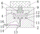
FIG. 1 is a schematic view of the overall front view structure of the present invention;
FIG. 2 is a schematic view of the right-side cross-sectional structure of the workbench of the present invention;
FIG. 3 is a schematic top view of the cross-sectional structure of the fixing plate of the present invention;
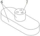
fig. 4 is a schematic view of the three-dimensional structure of the fixing block of the present invention;
fig. 5 is a schematic view of the three-dimensional structure of the support pillar of the present invention.
In the figure: 1. hot die forging the press body; 2. a work table; 3. a first movable slot; 4. fixing the disc; 5. a second movable slot; 6. a fixed block; 7. a through hole; 8. forming a module; 9. a fixing hole; 10. a chute; 11. a spring; 12. a clamping and connecting rod; 13. a hauling rope; 14. a rocker; 15. a support pillar; 16. a pedal.
Detailed Description
The technical solutions in the embodiments of the present invention will be described clearly and completely with reference to the accompanying drawings in the embodiments of the present invention, and it is obvious that the described embodiments are only some embodiments of the present invention, not all embodiments. Based on the embodiments in the present invention, all other embodiments obtained by a person skilled in the art without creative work belong to the protection scope of the present invention.
Referring to fig. 1-5, the present invention provides a technical solution: a hot die forging press easy to operate comprises a hot die forging press body 1, a forming module 8, a traction rope 13 and a pedal 16, wherein a workbench 2 is fixedly installed at the upper end of the hot die forging press body 1, a first movable groove 3 is formed in the workbench 2, a fixed disc 4 is arranged in the workbench 2, a second movable groove 5 is formed in the fixed disc 4, a fixed block 6 is arranged in the second movable groove 5, a through hole 7 is formed in the fixed block 6, the forming module 8 is installed at the upper end of the fixed block 6, the lower end of the forming module 8 is connected with the upper surface of the workbench 2, a fixed hole 9 is formed at the lower end of the fixed disc 4, a sliding groove 10 is formed in the workbench 2, a spring 11 is arranged in the sliding groove 10, a clamping rod 12 is arranged at the upper end of the spring 11, the clamping rod 12 is connected with the fixed hole 9, the traction rope 13 is connected with the bottom of the clamping rod, and the tail end of the traction rope 13 is connected with a rocker 14, a support column 15 is fixedly installed on the outer surface of the rocker 14, and a pedal 16 is fixedly installed at the outer end of the rocker 14.
A rotating structure is formed between the fixed disc 4 and the workbench 2, the diameter of the fixed disc 4 is equal to the length of the fixed block 6, and the diameter of the fixed disc 4 is equal to the length of the fixed block 6, so that the subsequent fixed disc 4 can drive the fixed block 6 to rotate in the workbench 2, and the subsequent fixed disc 4 can be fixed in the workbench 2.
The broadside of fixed block 6 is the arc structure, and through-hole 7 is in the equal angular distribution of the inside of fixed block 6, and the broadside is the fixed block 6 of arc structure, can reduce the frictional force of fixed block 6 and workstation 2 to the at utmost, makes the rotation of fixed disk 4 in workstation 2 become more light.
For bolted connection between shaping module 8 and the fixed block 6, and all constitute sliding construction between fixed block 6 and first movable groove 3 and the second movable groove 5, and be bolted connection's shaping module 8 between the fixed block 6, be favorable to follow-up shaping module 8's change, reduced the time of changing shaping module 8 and spending, improved the production efficiency of hot die forging press.
The cross sectional shape of joint pole 12 is "Y" shape, and joint pole 12 passes through and constitutes extending structure between spring 11 and the spout 10, and the cross sectional shape is the joint pole 12 of "Y" shape, can carry out the block to two fixed orificess 9 that the fixed disk 4 lower extreme was seted up simultaneously, is favorable to the fixed of follow-up fixed disk 4.
The supporting columns 15 are symmetrically distributed about the longitudinal center line of the rocker 14, a rotating structure is formed between the supporting columns 15 and the workbench 2, the supporting columns 15 are symmetrically distributed about the longitudinal center line of the rocker 14 and a rotating structure is formed between the supporting columns 15 and the workbench 2, the rocker 14 is controlled to rotate inside the workbench 2 by stepping on and pressing the pedal 16, and the clamping rods 12 are favorably separated from the fixing holes 9 when the molding module 8 is replaced.
The working principle is as follows: according to the figures 1-4, firstly, a forming module 8 is fixedly connected with a fixed block 6 through a bolt and a through hole 7 manually, then, the short edge of the fixed block 6 is aligned with a first movable groove 3 formed in a workbench 2 fixedly installed at the upper end of a hot die forging press body 1 and then inserted, so that the forming module 8 and the fixed block 6 respectively slide in the upper surface of the workbench 2 and the first movable groove 3, the fixed block 6 slides into a second movable groove 5 formed in a fixed disc 4 through the first movable groove 3, then the forming module 8 is rotated, the forming module 8 drives the fixed block 6 and the fixed disc 4 to rotate until the upper end of a clamping rod 12 is clamped into a fixed hole 9 formed at the lower end of the fixed disc 4, and the installation of the forming module 8 is completed;
according to fig. 1-3 and 5, when the forming module 8 needs to be replaced, the pedal 16 is pressed down with force, the pedal 16 drives the rocker 14 to rotate upwards in the workbench 2 through the supporting column 15, the rocker 14 pulls the traction rope 13, then the traction rope 13 pulls the clamping rod 12 to slide downwards in the sliding groove 10, the clamping rod 12 slides out of the fixing hole 9 and compresses the spring 11, then the forming module 8 is rotated manually, the second movable groove 5 is aligned with the first movable groove 3 and then slides out of the fixing block 6, and finally the operation of the previous stage is repeated, so that the replacement of the forming module 8 is completed, which is the working process of the whole device, and the content which is not described in detail in the description belongs to the prior art known by persons skilled in the art.
Although embodiments of the present invention have been shown and described, it will be appreciated by those skilled in the art that changes, modifications, substitutions and alterations can be made in these embodiments without departing from the principles and spirit of the invention, the scope of which is defined in the appended claims and their equivalents.
Claims (6)
1. The utility model provides an easy operation's hot die forging press, includes hot die forging press body (1), shaping module (8), haulage rope (13) and footboard (16), its characterized in that: the upper end of the hot die forging press body (1) is fixedly provided with a workbench (2), a first movable groove (3) is formed in the workbench (2), a fixed disc (4) is arranged in the workbench (2), a second movable groove (5) is formed in the fixed disc (4), a fixed block (6) is arranged in the second movable groove (5), a through hole (7) is formed in the fixed block (6), a forming module (8) is installed at the upper end of the fixed block (6), the lower end of the forming module (8) is connected with the upper surface of the workbench (2), a fixed hole (9) is formed at the lower end of the fixed disc (4), a sliding groove (10) is formed in the workbench (2), a spring (11) is arranged in the sliding groove (10), a clamping rod (12) is arranged at the upper end of the spring (11), and joint pole (12) are connected with fixed orifices (9), the bottom of joint pole (12) is connected with haulage rope (13), and the end of haulage rope (13) is connected with rocker (14), the outer fixed surface of rocker (14) installs support column (15), and the outer end fixed mounting of rocker (14) has footboard (16).
2. A simple to operate hot die forging press as claimed in claim 1, wherein: a rotating structure is formed between the fixed disc (4) and the workbench (2), and the diameter of the fixed disc (4) is equal to the length of the fixed block (6).
3. A simple to operate hot die forging press as claimed in claim 1, wherein: the wide sides of the fixing blocks (6) are of arc-shaped structures, and the through holes (7) are distributed in the fixing blocks (6) at equal angles.
4. A simple to operate hot die forging press as claimed in claim 1, wherein: the forming module (8) is connected with the fixing block (6) through bolts, and sliding structures are formed between the fixing block (6) and the first movable groove (3) and between the fixing block and the second movable groove (5).
5. A simple to operate hot die forging press as claimed in claim 1, wherein: the section shape of joint pole (12) is "Y" shape, and joint pole (12) pass through and constitute extending structure between spring (11) and spout (10).
6. A simple to operate hot die forging press as claimed in claim 1, wherein: the supporting columns (15) are symmetrically distributed about the longitudinal central line of the rocker (14), and a rotating structure is formed between the supporting columns (15) and the workbench (2).
Priority Applications (1)
| Application Number | Priority Date | Filing Date | Title |
|---|---|---|---|
| CN202021413159.3U CN212884778U (en) | 2020-07-17 | 2020-07-17 | Hot die forging press machine simple to operate |
Applications Claiming Priority (1)
| Application Number | Priority Date | Filing Date | Title |
|---|---|---|---|
| CN202021413159.3U CN212884778U (en) | 2020-07-17 | 2020-07-17 | Hot die forging press machine simple to operate |
Publications (1)
| Publication Number | Publication Date |
|---|---|
| CN212884778U true CN212884778U (en) | 2021-04-06 |
Family
ID=75288601
Family Applications (1)
| Application Number | Title | Priority Date | Filing Date |
|---|---|---|---|
| CN202021413159.3U Active CN212884778U (en) | 2020-07-17 | 2020-07-17 | Hot die forging press machine simple to operate |
Country Status (1)
| Country | Link |
|---|---|
| CN (1) | CN212884778U (en) |
-
2020
- 2020-07-17 CN CN202021413159.3U patent/CN212884778U/en active Active
Similar Documents
| Publication | Publication Date | Title |
|---|---|---|
| CN202539362U (en) | Small-angle conical part molding die | |
| CN108607890A (en) | A kind of novel die of rotary squeezing helical teeth internal gear | |
| CN108339959A (en) | A kind of shaft sleeve parts shaping dies | |
| CN112719254B (en) | Hydraulic ejection demoulding device for processing mould steel | |
| CN210548093U (en) | Pressure type forming die for metallurgical powder | |
| CN111872304A (en) | Wheel hub die carrier | |
| CN212857405U (en) | Gear shaft gear pressing forming tool | |
| CN206199995U (en) | A kind of flange shaping mould for punch process | |
| CN210617395U (en) | Hydraulic forming die | |
| CN214212078U (en) | Single-groove short-tail rivet one-step thread rolling forming die | |
| CN103600460A (en) | One-step molding combined mold for specially-shaped workpieces | |
| CN111375681B (en) | Z-axis linear motor mass block shaping die and assembling method thereof | |
| CN210045857U (en) | Fine adjustment type stamping mechanism and stamping equipment applying same | |
| CN210936747U (en) | Surface pressing and fixing device for machining precision die | |
| CN208305870U (en) | A kind of mesh piece pressing mold | |
| CN217252138U (en) | Stamping die is used in production of car reinforcing plate | |
| CN215508813U (en) | Steel ball preparation mould convenient to change | |
| CN208357566U (en) | A kind of material stamping equipment | |
| CN219766670U (en) | Ball stud upsetting device | |
| CN222537408U (en) | Pressing device for grinding wheel production | |
| CN219786273U (en) | Hardware chassis stamping die | |
| CN221312193U (en) | Press-fit tooling for disc spring forming | |
| CN222175644U (en) | A universal die for forming angles of aircraft profiles | |
| CN220880100U (en) | New energy automobile safety component bumper crossbeam punching press frock | |
| CN221133762U (en) | Hard alloy stamping die for automobile connecting piece |
Legal Events
| Date | Code | Title | Description |
|---|---|---|---|
| GR01 | Patent grant | ||
| GR01 | Patent grant |