CN212884563U - Seat riveting machine - Google Patents
Seat riveting machine Download PDFInfo
- Publication number
- CN212884563U CN212884563U CN202021129404.8U CN202021129404U CN212884563U CN 212884563 U CN212884563 U CN 212884563U CN 202021129404 U CN202021129404 U CN 202021129404U CN 212884563 U CN212884563 U CN 212884563U
- Authority
- CN
- China
- Prior art keywords
- riveting
- clamping plate
- seat
- type pincers
- semicircular groove
- Prior art date
- Legal status (The legal status is an assumption and is not a legal conclusion. Google has not performed a legal analysis and makes no representation as to the accuracy of the status listed.)
- Active
Links
Images


Landscapes
- Jigs For Machine Tools (AREA)
Abstract
The utility model relates to a seat is to riveting the field, a seat is to riveter is disclosed, including lathe base and clamping device and the riveting set of setting on the lathe base, still include the C type pincers body that two symmetries set up in opposite directions, the upper portion of the C type pincers body is equipped with riveting set, the lower part tip of the C type pincers body upwards forms the clamp base, be equipped with clamping device on the clamp base, riveting device's riveting head sets up relatively on two C type pincers bodies, two clamping device's the position of cramping and two riveting device's riveting head are in same horizontal plane, two C type pincers body below all are equipped with the removal slip table that makes two C type pincers bodies relative or move in opposite directions, it even has the slip table cylinder to remove the slip table. The utility model discloses the seat can play good support to the seat pipe to the riveter, prevents to warp, and the riveting quality is high.
Description
Technical Field
The utility model relates to a seat is to riveting the field, concretely relates to seat is to riveter.
Background
When the existing seat is used for a riveting machine, a product is placed into the fixture, one side of the circular tube is fixed by the semicircular U-shaped part, the other side of the circular tube is obliquely and tightly pressed by the oblique pressing device, the upper part of the circular tube is pressed by the pressing plate, and the fixed ends of the two sides of the circular tube are riveted by the riveting machine, so that a phenomenon can occur in the riveting process: because the pipe is circular, when being supported by the U type, can make on the pipe the upper half of welding do not support, under the condition that lacks the support, along with the removal of riveter die, the welding on the pipe will appear warping, lead to the size of pipe both sides welding to appear upside subtly afterwards, the phenomenon that the downside is big partially, this phenomenon can correct through correction mode when the seat equipment in the past, but along with the maturity of auto industry development, the host computer factory has proposed higher requirement to the accessory factory, it becomes the requirement and the task of ruling into to improve product quality, consequently under kind of circumstances, new seat becomes the design of riveter not ruling.
Disclosure of Invention
The utility model aims at providing a seat is to riveter to the not enough of above-mentioned technique, can play good support to the seat pipe, prevents to warp, and the riveting quality is high.
In order to realize the above-mentioned purpose, the utility model discloses a seat is to riveter, be in including lathe base and setting clamping device and the riveting set on the lathe base still include the C type pincers body that two symmetries set up in opposite directions, the upper portion of the C type pincers body is equipped with riveting set, the lower part tip of the C type pincers body upwards forms the tight base of clamp, be equipped with on the tight base of clamp clamping device, two riveting set's on the C type pincers body riveting head sets up relatively, two clamping device's the position of pressing from both sides and two riveting set's riveting head is in same horizontal plane, two C type pincers body below all is equipped with makes two the relative or relative motion's of the C type pincers body removal slip table, it has the slip table cylinder to move the slip table even.
Preferably, clamping device includes lower grip block and last grip block, lower grip block fixed mounting be in on the tight base of clamp, there is die clamping cylinder through the support mounting on the tight base of clamp, it passes through die clamping cylinder installs the top of lower grip block to go up the grip block, lower grip block upper surface is opened there is lower half slot that link up, lower half slot with riveting set's rivet joint is in on the same straight line, go up open on the grip block lower surface have with half slot complex last half slot down, the round hole that forms after half slot and the last half slot are closed down with the pipe clearance fit on the seat.
Preferably, the upper clamping plate is provided with two vertical first guide posts which are fixed on the lower clamping plate and face the upper semicircular groove, two vertical second guide posts are fixed on the other side of the upper semicircular groove, two guide grooves matched with the second guide posts are formed in the lower clamping plate, the depth of each guide groove is larger than the distance between the bottom end of each second guide post and the lower surface of the upper clamping plate, and the upper clamping plate is far away from the lower clamping plate, the distance between the bottom end of each second guide post and the lower clamping plate is larger than the diameter of the circular tube on the seat.
Preferably, an upper bolt stop is arranged at one end, close to the riveting head of the riveting device, of the upper clamping plate, a semicircular groove matched with the upper semicircular groove is formed in the upper bolt stop, a lower bolt stop matched with the upper bolt stop is arranged on the lower clamping plate, and a semicircular groove matched with the lower semicircular groove is formed in the lower bolt stop.
Preferably, the bottom end of the second guide post is conical, so that additional torque can not be blocked in the ascending and descending processes.
Compared with the prior art, the utility model, have following advantage:
1. the seat round pipe can be well supported, deformation is prevented, and riveting quality is high;
2. the working action is less, and the working beat is improved;
3. the riveting head of the riveting device is connected and moved through the C-shaped clamp body, the seat is tensioned through the sliding table cylinder matched with the movable sliding table, the clamping device on each side clamp body is independently supported in the riveting direction during riveting, the middle part of the circular tube is subjected to smaller extrusion force, and deformation is avoided;
4. when the product is in the shape changing aspect, the product with different diameters can be adapted only by replacing the upper clamping plate and the lower clamping plate, the products with different lengths can be adapted by adjusting the stroke of the sliding table cylinder, and the product is convenient to replace and good in universality;
5. the riveting machine has the advantages that the riveting machine is improved by one grade compared with the conventional riveting machine in terms of process, tempo, product replacement and the like, the product quality and stability are improved, the capacity is increased, the operation of field personnel is reduced, the purchasing cost of enterprises is saved, and the riveting machine has wide popularization value.
Drawings
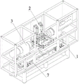
Fig. 1 is a schematic structural view of the seat riveting machine of the present invention;
FIG. 2 is a top view of FIG. 1;
FIG. 3 is a schematic view of the clamping device and the riveting device on the C-shaped clamp body in FIG. 1;
fig. 4 is an axial view of the seat riveting machine of the present invention.
The components in the figures are numbered as follows:
the riveting device comprises a machine tool base 1, a clamping device 2, a riveting device 3, a C-shaped clamp body 4, a clamping base 5, a riveting head 6, a movable sliding table 7, a sliding table air cylinder 8, a lower clamping plate 9, an upper clamping plate 10, a support 11, a clamping air cylinder 12, a lower semicircular groove 13, an upper semicircular groove 14, a first guide column 15, a second guide column 16, a guide groove 17, an upper bolt stop block 18, a lower bolt stop block 19 and a circular tube 20.
Detailed Description
The present invention will be described in further detail with reference to the following drawings and specific embodiments.
As shown in fig. 1, fig. 2, fig. 3 and fig. 4, the utility model discloses seat is to riveter, including lathe base 1 and clamping device 2 and the riveting device 3 of setting on lathe base 1, still include two C type pincers bodies 4 that set up in opposite symmetry, the upper portion of C type pincers body 4 is equipped with riveting device 3, the lower part tip of C type pincers body 4 upwards forms and presss from both sides tight base 5, be equipped with clamping device 2 on pressing from both sides tight base 5, riveting head 6 of riveting device 3 sets up relatively on two C type pincers bodies 4, the position of the clamp of two clamping device 2 and riveting head 6 of two riveting device 3 are in same horizontal plane, two C type pincers bodies 4 below all are equipped with the removal slip table 7 that makes two C type pincers bodies 4 relative or move in opposite directions, removal slip table 7 even has slip table cylinder 8.
As shown in fig. 3, the clamping device 2 includes a lower clamping plate 9 and an upper clamping plate 10, the lower clamping plate 9 is fixedly mounted on the clamping base 5, a clamping cylinder 12 is mounted on the clamping base 5 through a bracket 11, the upper clamping plate 10 is mounted above the lower clamping plate 9 through the clamping cylinder 12, a lower through semicircular groove 13 is formed in the upper surface of the lower clamping plate 9, the lower semicircular groove 13 and the riveting head 6 of the riveting device 3 are in the same straight line, an upper semicircular groove 14 matched with the lower semicircular groove 13 is formed in the lower surface of the upper clamping plate 10, and a circular hole formed after the lower semicircular groove 13 and the upper semicircular groove 14 are closed is in clearance fit with a circular tube 20 on the seat.
In addition, as shown in fig. 3, two vertical first guide posts 15 are inserted into the upper clamping plate 10 at positions facing the bracket 11 of the upper semicircular groove 14, the two first guide posts 15 are fixed on the lower clamping plate 9, two vertical second guide posts 16 are fixed on the upper clamping plate 10 at positions on the other side of the upper semicircular groove 14, the bottom ends of the second guide posts 16 are tapered, two guide grooves 17 matched with the second guide posts 16 are arranged on the lower clamping plate 9, the depth of each guide groove 17 is greater than the distance from the bottom end of each second guide post 16 to the lower surface of the upper clamping plate 10, and when the upper clamping plate 10 is far away from the lower clamping plate 9, the distance from the bottom end of each second guide post 16 to the lower clamping plate 9 is greater than the diameter of the seat upper circular tube 20.
In this embodiment, an upper bolt stop 18 is arranged at one end of the upper clamping plate 10 close to the riveting head 6 of the riveting device 3, a semicircular groove matched with the upper semicircular groove 14 is arranged on the upper bolt stop 18, a lower bolt stop 19 matched with the upper bolt stop 18 is arranged on the lower clamping plate 9, and a semicircular groove matched with the lower semicircular groove 13 is arranged on the lower bolt stop 19.
When the riveting device is used, firstly, the upper clamping plates 10 on the two C-shaped clamp bodies 4 are far away from the lower clamping plate 9 through the clamping cylinder 12, then the round tube 20 of the seat is placed in the seat, namely the round tube 20 is prevented from being arranged on the lower semicircular grooves 14 of the two lower clamping plates 9, then the upper clamping plate 10 is lowered through the clamping cylinder 12, the upper clamping plate 10 is inosculated with the lower clamping plate 9 under the action of the first guide column 15 and the second guide column 16, the lower semicircular grooves 13 and the upper semicircular grooves 14 form round holes to enclose the round tube 20 and be in clearance fit with the round tube 20, then the two sliding table cylinders 8 drive the movable sliding table 7 to respectively move towards two ends, so that the two clamping devices 2 strain two ends of the round tube 20, then the two riveting devices 3 are started to rivet, after the riveting is finished, the riveting head 6 returns, the two sliding cylinders 8 reset to drive the movable sliding table 8 to reset, then the clamping cylinder 12 drives the upper clamping, the seat can be removed by loosening the tube 20.
The seat riveting machine of the utility model can well support the seat round tube 20, prevent deformation and has high riveting quality; the working action is less, and the working beat is improved; the riveting head 6 of the riveting device 3 is connected and moved through the C-shaped clamp body 4, the seat is tensioned through the sliding table cylinder 8 matched with the movable sliding table 7, the clamping device 2 on each side clamp body is independently supported in the riveting direction during riveting, the middle part of the circular tube 20 is subjected to smaller extrusion force, and deformation is avoided; when the product is in the shape changing aspect, products with different diameters can be adapted only by replacing the upper clamping plate 10 and the lower clamping plate 9, products with different lengths can be adapted by adjusting the stroke of the sliding table cylinder 8, and the product is convenient to replace and good in universality; the riveting machine has the advantages that the riveting machine is improved by one grade compared with the conventional riveting machine in terms of process, tempo, product replacement and the like, the product quality and stability are improved, the capacity is increased, the operation of field personnel is reduced, the purchasing cost of enterprises is saved, and the riveting machine has wide popularization value.
Claims (5)
1. The utility model provides a seat is to riveter, includes machine tool base (1) and sets up clamping device (2) and riveting set (3) on machine tool base (1), its characterized in that: still include two C type pincers bodies (4) that symmetry set up in opposite directions, the upper portion of C type pincers body (4) is equipped with riveting set (3), the lower part tip of C type pincers body (4) upwards forms and presss from both sides tight base (5), it is equipped with on tight base (5) clamping device (2), two riveting head (6) of riveting set (3) set up relatively on C type pincers body (4), two the tight position of clamp of clamping device (2) and two riveting head (6) of riveting set (3) are in same horizontal plane, two C type pincers body (4) below all is equipped with makes two the relative or relative motion's of C type pincers body (4) removal slip table (7), it even has slip table cylinder (8) to remove slip table (7).
2. The seat riveting machine according to claim 1, wherein: clamping device (2) are including lower grip block (9) and last grip block (10), lower grip block (9) fixed mounting be in press from both sides tightly on base (5), install die clamping cylinder (12) through support (11) on pressing from both sides tight base (5), it passes through to go up grip block (10) install die clamping cylinder (12) are in the top of lower grip block (9), lower grip block (9) upper surface is opened has lower half slot (13) that link up down, half slot (13) down with rivet joint (6) of riveting set (3) are in on the same straight line, go up grip block (10) lower surface on open have with half slot (13) complex last semicircle groove (14) down, the round hole that forms after semicircle slot (13) and last semicircle groove (14) are closed down and pipe (20) clearance fit on the seat.
3. The seat riveting machine according to claim 2, wherein: two vertical first guide posts (15) are penetrated at the position, facing the bracket (11), of the upper semicircular groove (14) on the upper clamping plate (10), the two first guide posts (15) are fixed on the lower clamping plate (9), two vertical second guide posts (16) are fixed on the upper clamping plate (10) at the other side of the upper semicircular groove (14), two guide grooves (17) matched with the second guide columns (16) are arranged on the lower clamping plate (9), the depth of the guide groove (17) is larger than the distance from the bottom end of the second guide column (16) to the lower surface of the upper clamping plate (10), when the upper clamping plate (10) is far away from the lower clamping plate (9), the distance from the bottom end of the second guide column (16) to the lower clamping plate (9) is larger than the diameter of the seat upper round pipe (20).
4. The seat riveting machine according to claim 3, wherein: one end, close to the riveting head (6) of the riveting device (3), of the upper clamping plate (10) is provided with an upper bolt stop block (18), a semicircular groove matched with the upper semicircular groove (14) is formed in the upper bolt stop block (18), a lower bolt stop block (19) matched with the upper bolt stop block (18) is formed in the lower clamping plate (9), and a semicircular groove matched with the lower semicircular groove (13) is formed in the lower bolt stop block (19).
5. The seat riveting machine according to claim 4, wherein: the bottom end of the second guide column (16) is conical.
Priority Applications (1)
| Application Number | Priority Date | Filing Date | Title |
|---|---|---|---|
| CN202021129404.8U CN212884563U (en) | 2020-06-16 | 2020-06-16 | Seat riveting machine |
Applications Claiming Priority (1)
| Application Number | Priority Date | Filing Date | Title |
|---|---|---|---|
| CN202021129404.8U CN212884563U (en) | 2020-06-16 | 2020-06-16 | Seat riveting machine |
Publications (1)
| Publication Number | Publication Date |
|---|---|
| CN212884563U true CN212884563U (en) | 2021-04-06 |
Family
ID=75278585
Family Applications (1)
| Application Number | Title | Priority Date | Filing Date |
|---|---|---|---|
| CN202021129404.8U Active CN212884563U (en) | 2020-06-16 | 2020-06-16 | Seat riveting machine |
Country Status (1)
| Country | Link |
|---|---|
| CN (1) | CN212884563U (en) |
Cited By (1)
| Publication number | Priority date | Publication date | Assignee | Title |
|---|---|---|---|---|
| CN116372085A (en) * | 2023-03-08 | 2023-07-04 | 宁波霍科电器有限公司 | A kind of automatic riveting equipment |
-
2020
- 2020-06-16 CN CN202021129404.8U patent/CN212884563U/en active Active
Cited By (2)
| Publication number | Priority date | Publication date | Assignee | Title |
|---|---|---|---|---|
| CN116372085A (en) * | 2023-03-08 | 2023-07-04 | 宁波霍科电器有限公司 | A kind of automatic riveting equipment |
| CN116372085B (en) * | 2023-03-08 | 2024-06-07 | 宁波霍科电器有限公司 | An automatic riveting equipment |
Similar Documents
| Publication | Publication Date | Title |
|---|---|---|
| CN112238184A (en) | Pipe clamp stamping die | |
| CN111215490B (en) | Double-end bending machine for metal pipe | |
| CN112077491A (en) | Axle housing accessory welding tool | |
| CN212822769U (en) | Semi-automatic clamping general tool for turning inner circle of flywheel gear ring | |
| JP2558928Y2 (en) | Press brake | |
| CN211589048U (en) | Car return bend welding fixation clamp | |
| CN211192688U (en) | Variable speed hoist and mount crossbeam welding frock | |
| CN221454118U (en) | Pipe fitting equipment of taking lead | |
| CN220196144U (en) | Section bar sleeve riveting device | |
| CN213104246U (en) | Rapid assembly equipment for brake line connectors | |
| CN108326225B (en) | Forging material conveying device for stamping steel balls | |
| CN218283431U (en) | Sheet metal part mould with positioning function | |
| CN222695830U (en) | Quick-release device for upper die of bending machine | |
| CN208696200U (en) | A forging pneumatic clamp | |
| CN210172438U (en) | Small reed pipe forming machine | |
| CN211162597U (en) | High-precision automobile part welding fixture | |
| KR101418043B1 (en) | Hemming apparatus for manufacturing a draft automobile by press | |
| CN117282862B (en) | Condenser collecting pipe and drying bottle riveting machine | |
| CN209288192U (en) | A kind of fixed device of improved forging and stamping | |
| CN209697832U (en) | Pedal arm support tube riveting die | |
| CN219253897U (en) | Automatic spin riveting machine of rocker production line | |
| CN222695814U (en) | Quick clamping device for upper die of bending machine | |
| CN223718768U (en) | Tool for quickly and accurately assembling piston rod stop ring | |
| CN212886090U (en) | Press fit eye type joint rod device | |
| CN220592827U (en) | Self-centering pneumatic vice |
Legal Events
| Date | Code | Title | Description |
|---|---|---|---|
| GR01 | Patent grant | ||
| GR01 | Patent grant |