CN212873416U - Noise reduction structure of computer case - Google Patents
Noise reduction structure of computer case Download PDFInfo
- Publication number
- CN212873416U CN212873416U CN202022339086.4U CN202022339086U CN212873416U CN 212873416 U CN212873416 U CN 212873416U CN 202022339086 U CN202022339086 U CN 202022339086U CN 212873416 U CN212873416 U CN 212873416U
- Authority
- CN
- China
- Prior art keywords
- air inlet
- heat dissipation
- main frame
- frame body
- holes
- Prior art date
- Legal status (The legal status is an assumption and is not a legal conclusion. Google has not performed a legal analysis and makes no representation as to the accuracy of the status listed.)
- Expired - Fee Related
Links
- 230000009467 reduction Effects 0.000 title claims description 34
- 230000017525 heat dissipation Effects 0.000 claims abstract description 43
- 230000007246 mechanism Effects 0.000 claims abstract description 33
- 238000010521 absorption reaction Methods 0.000 claims description 12
- 230000035939 shock Effects 0.000 claims description 11
- 230000002093 peripheral effect Effects 0.000 claims description 9
- 239000000428 dust Substances 0.000 claims description 7
- XAGFODPZIPBFFR-UHFFFAOYSA-N aluminium Chemical compound [Al] XAGFODPZIPBFFR-UHFFFAOYSA-N 0.000 claims description 6
- 229910052782 aluminium Inorganic materials 0.000 claims description 6
- 238000009423 ventilation Methods 0.000 claims description 6
- 238000013016 damping Methods 0.000 claims description 5
- 229920001971 elastomer Polymers 0.000 claims description 4
- 238000001914 filtration Methods 0.000 claims description 4
- 230000000694 effects Effects 0.000 abstract description 7
- 238000000034 method Methods 0.000 abstract description 4
- 230000009977 dual effect Effects 0.000 abstract description 2
- 238000002360 preparation method Methods 0.000 abstract description 2
- 239000000463 material Substances 0.000 description 4
- 230000008569 process Effects 0.000 description 2
- 206010068150 Acoustic shock Diseases 0.000 description 1
- 229920005830 Polyurethane Foam Polymers 0.000 description 1
- 230000000712 assembly Effects 0.000 description 1
- 238000000429 assembly Methods 0.000 description 1
- 230000009286 beneficial effect Effects 0.000 description 1
- 230000005540 biological transmission Effects 0.000 description 1
- 229920005549 butyl rubber Polymers 0.000 description 1
- 238000010586 diagram Methods 0.000 description 1
- 239000011888 foil Substances 0.000 description 1
- 239000012535 impurity Substances 0.000 description 1
- 239000007788 liquid Substances 0.000 description 1
- 238000004519 manufacturing process Methods 0.000 description 1
- 238000012986 modification Methods 0.000 description 1
- 230000004048 modification Effects 0.000 description 1
- 230000003287 optical effect Effects 0.000 description 1
- 239000011496 polyurethane foam Substances 0.000 description 1
- 230000001105 regulatory effect Effects 0.000 description 1
Images



Landscapes
- Cooling Or The Like Of Electrical Apparatus (AREA)
Abstract
The utility model discloses a structure of making an uproar falls in computer machine case relates to computer machine case preparation technical field. The utility model comprises a main frame body; the end surface and the top surface of the main frame body are both fixedly provided with air inlet holes; heat dissipation holes are formed in the two side faces of the main frame body; a mainboard mounting rack matched with the heat dissipation holes is fixedly mounted on one side surface of the main frame body; the inner walls of the two air inlet holes are fixedly provided with air inlet mechanisms; the inner walls of the two radiating holes are fixedly provided with air exhaust mechanisms. The utility model discloses a design of electronic tripe in air inlet mechanism and the heat dissipation mechanism, the fixed heat radiating area who becomes traditional computer machine case is heat radiating area with adjustable, through heat radiating area's adjustable, effectively improve the device's radiating effect then, fall the design of making an uproar blade, heat dissipation ventilating board and air inlet filter plate through the tripe in air inlet mechanism and the heat dissipation mechanism simultaneously, can be at the air inlet and the in-process of airing exhaust, carry out dual second grade to the wind regime of supplying with exhaust hot-blast and inhale the sound and fall the noise.
Description
Technical Field
The utility model belongs to the technical field of computer machine case preparation, especially, relate to a structure of making an uproar falls in computer machine case.
Background
As is well known, computers have become an indispensable tool in production and life; however, as computer performance improves, its noise problem becomes more severe; the noise source of the computer mainly comprises components such as a CPU fan, a display card fan, a power supply fan, an optical drive, a hard disk and the like; in order to reduce noise, people use a fan with large size, low rotating speed and low noise, and even add a water-cooled structure; the biggest problems of the water-cooled structure are that: the heat conduction pipes are more, the structure is complex, and the cost is very high; the liquid has leakage risk and has fatal threat to the computer; the noise reduction capability of the low-noise fan is limited, and as the fan ages, the sound is increased continuously, so that a novel noise reduction structure of the computer case is urgently needed in the market to solve the problems.
SUMMERY OF THE UTILITY MODEL
An object of the utility model is to provide a structure of making an uproar falls in computer machine case through the design of air inlet mechanism and heat dissipation mechanism, has solved the current poor problem of the structure of making an uproar fall in computer machine case noise reduction effect.
In order to solve the technical problem, the utility model discloses a realize through following technical scheme:
the utility model relates to a noise reduction structure of a computer case, which comprises a main frame body; the end surface and the top surface of the main frame body are both fixedly provided with air inlet holes; heat dissipation holes are formed in the two side faces of the main frame body; a mainboard mounting rack matched with the heat dissipation holes is fixedly mounted on one side surface of the main frame body; the inner walls of the two air inlet holes are fixedly provided with air inlet mechanisms; the inner walls of the two radiating holes are fixedly provided with air exhaust mechanisms; the end surface and the top surface of the main frame body are magnetically attracted with a dust filtering net matched with the air inlet hole; the two side surfaces of the main frame body are fixedly provided with heat dissipation ventilating plates matched with the heat dissipation holes through connecting pieces; the surfaces of the radiating and ventilating plates are uniformly provided with ventilating holes;
the air inlet mechanism comprises a mounting frame a; the peripheral side surface of the mounting frame a is fixedly connected with the air inlet hole; the inner wall of the mounting frame a is fixedly provided with a sound-absorbing electric shutter assembly a; an air inlet filter plate is fixedly mounted on the top surface of the mounting frame a; the surface of the air inlet filter plate is uniformly provided with air inlet filter holes; the surface of the air inlet filter plate is fixedly communicated with a group of fan mounting seats which are distributed in a linear array;
the air exhaust mechanism comprises a mounting frame b; the peripheral side surface of the mounting frame b is fixedly connected with the heat dissipation hole; the inner wall of the mounting frame b is fixedly provided with a sound-absorbing electric shutter assembly b;
the sound-absorbing electric shutter assembly a and the sound-absorbing electric shutter assembly b comprise shutter frames; the peripheral side surface of the shutter frame is fixedly connected with the mounting frame a; a group of louver noise reduction blades which are mutually connected through chains are rotatably connected between the inner surfaces of the louver frames; a driving motor is fixedly arranged in the louver frame; one end of the output shaft of the driving motor is fixedly connected with the shutter noise reduction blade
Preferably, the main frame body, the louver noise reduction blades, the air inlet filter plate and the heat dissipation ventilation plate all comprise an aluminum plate layer, a damping layer, a buffer layer and a sound attenuation layer which are sequentially connected from outside to inside.
Preferably, damping shock pads are arranged at the joints of the heat dissipation ventilating plate and the main frame body and the joints of the air inlet filter plate and the mounting frame a; an axial flow mute fan is fixedly arranged in the fan mounting seat; and a rubber cushion ring is fixedly arranged at the joint of the axial flow mute fan and the fan mounting seat.
Preferably, the bottom surface of the main frame body is fixedly connected with two symmetrically arranged shock absorption support legs; a control panel is fixedly arranged on the end face of the main frame body; the back of the main frame body is fixedly provided with a wire passing hole.
Preferably, the main frame body is of a hollow box-shaped structure; the inner wall of the fan mounting seat is also fixedly paved with a sound-absorbing ring; the air inlet hole and the heat dissipation holes are square holes; the cross section of the main board mounting rack is of a U-shaped structure.
The utility model discloses following beneficial effect has:
the utility model discloses a design of electronic tripe in air inlet mechanism and the heat dissipation mechanism, become the fixed heat radiating area of traditional computer machine case and be heat radiating area with adjustable, adjustable through heat radiating area, then effectively improve the device's radiating effect, simultaneously through the tripe in air inlet mechanism and the heat dissipation mechanism blade of making an uproar falls, the design of heat dissipation ventilating board and air inlet filter plate, can be at the air inlet and the in-process of airing exhaust, carry out dual second grade to the wind regime of supplying with exhaust hot-blast and inhale the sound and fall and make an uproar, and through the main frame body, the heat dissipation ventilating board, the enclosed design of air inlet filter plate, can effectively reduce the probability that the noise flows, then fully guarantee the noise reduction of.
Of course, it is not necessary for any particular product to achieve all of the above-described advantages at the same time.
Drawings
In order to more clearly illustrate the technical solutions of the embodiments of the present invention, the drawings used in the description of the embodiments will be briefly introduced below, and it is obvious that the drawings in the following description are only some embodiments of the present invention, and it is obvious for those skilled in the art that other drawings can be obtained according to these drawings without creative efforts.
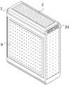
FIG. 1 is a schematic structural diagram of a noise reduction structure of a computer case;
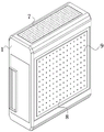
FIG. 2 is a schematic view of the structure of FIG. 1 from another angle;
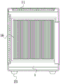
FIG. 3 is a schematic cross-sectional view of FIG. 1;
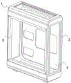
FIG. 4 is a schematic cross-sectional view of FIG. 1 in another direction;
FIG. 5 is a schematic structural view of the main frame, the air inlet holes and the heat dissipation holes;
FIG. 6 is a schematic structural view of an air intake filter plate and an air intake filter hole;
FIG. 7 is a schematic structural view of the air intake mechanism;
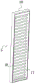
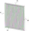
FIG. 8 is a schematic structural view of the air exhausting mechanism;
FIG. 9 is a schematic cross-sectional view of the aluminum plate layer, the shock-absorbing layer, the buffer layer and the sound-deadening layer;
in the drawings, the components represented by the respective reference numerals are listed below:
1. a main frame body; 2. an air inlet hole; 3. heat dissipation holes; 4. a mainboard mounting rack; 5. an air inlet mechanism; 6. an air exhaust mechanism; 7. a dust filter screen; 8. a heat dissipating and ventilating plate; 9. a vent hole; 10. a mounting frame a; 11. a sound-absorbing electric louver assembly a; 12. an air inlet filter plate; 13. an air inlet filter hole; 14. a fan mounting base; 15. a mounting frame b; 16. sound-absorbing electric louver assemblies b; 17. a louver frame; 18. a louver noise reduction blade; 19. an aluminum plate layer; 20. a shock-absorbing layer; 21. a buffer layer; 22. a sound-deadening layer; 23. shock absorption support legs; 24. a control panel.
Detailed Description
The technical solutions in the embodiments of the present invention will be described clearly and completely with reference to the accompanying drawings in the embodiments of the present invention, and it is obvious that the described embodiments are only some embodiments of the present invention, not all embodiments. Based on the embodiments of the present invention, all other embodiments obtained by a person of ordinary skill in the art without creative efforts belong to the protection scope of the present invention.
Referring to fig. 1-9, the present invention relates to a noise reduction structure for a computer case, which comprises a main frame 1; the end surface and the top surface of the main frame body 1 are both fixedly provided with air inlet holes 2; the air inlet hole 2 is used for continuously supplying cold air to the device;
two side surfaces of the main frame body 1 are provided with heat dissipation holes 3; the heat dissipation holes 3 are arranged to discharge hot air inside the device;
a mainboard mounting rack 4 matched with the heat dissipation holes 3 is fixedly mounted on one side surface of the main frame body 1; the main board mounting rack 4 is used for mounting operation of a main board and other equipment; the inner walls of the two air inlet holes 2 are both fixedly provided with an air inlet mechanism 5; the air inlet odd-even strands 5 are air inlet driving sources, and the inner walls of the two heat dissipation holes 3 are fixedly provided with air exhaust mechanisms 6; the air exhaust mechanism 6 is used for exhausting hot air inside the device;
the end surface and the top surface of the main frame body 1 are magnetically attracted with a dust filtering net 7 matched with the air inlet hole 2; the dust filter 7 is used for pre-filtering the impurities in the inlet air, and the magnetic strips are arranged at the bottom of the dust filter 7, so that the dust filter 7 can be maintained quickly;
the two side surfaces of the main frame body 1 are fixedly provided with heat dissipation ventilating plates 8 matched with the heat dissipation holes 3 through connecting pieces; the surfaces of the heat dissipation ventilating plates 8 are uniformly provided with ventilating holes 9;
the air inlet mechanism 5 comprises a mounting frame a 10; the peripheral side surface of the mounting frame a10 is fixedly connected with the air inlet 2; the inner wall of the mounting frame a10 is fixedly provided with a sound-absorbing electric shutter assembly a 11; the top surface of the mounting frame a10 is fixedly provided with an air inlet filter plate 12; the surface of the air inlet filter plate 12 is uniformly provided with air inlet filter holes 13; the surface of the air inlet filter plate 12 is fixedly communicated with a group of fan mounting seats 14 which are distributed in a linear array;
the exhaust mechanism 6 comprises a mounting frame b 15; the peripheral side surface of the mounting frame b15 is fixedly connected with the heat dissipation hole 3; the inner wall of the mounting frame b15 is fixedly provided with a sound-absorbing electric shutter assembly b 16;
the sound-absorbing electric louver assembly a11 and the sound-absorbing electric louver assembly b16 both comprise louver frames 17; the peripheral side surface of the louver frame 17 is fixedly connected with a mounting frame a 10; a group of louver noise reduction blades 18 which are mutually connected through chains are rotatably connected between the inner surfaces of the louver frames 17; a driving motor is fixedly arranged in the louver frame 17; one end of the output shaft of the driving motor is fixedly connected with one of the louver noise reduction blades 18.
Further as shown in fig. 9, the main frame body 1, the louver noise reduction blades 18, the air intake filter plate 12, and the heat dissipation ventilation plate 8 all include an aluminum plate layer 19, a shock absorption layer 20, a buffer layer 21, and a sound attenuation layer 22 that are sequentially connected from outside to inside, the shock absorption layer 20 is a pitch layer or a butyl rubber layer, the shock absorption layer 20 filters low-frequency noise by using an acoustic shock absorption material, the buffer layer 21 is an aluminum foil layer, the buffer layer 21 has a certain heat conduction effect at the same time, the sound attenuation layer 22 is made of a polyurethane foam material, and the above structure is not repeated herein for the existing mechanism.
Furthermore, damping shock-absorbing pads are arranged at the joints of the heat dissipation ventilating plate 8 and the main frame body 1 and the joints of the air inlet filter plate 12 and the mounting frame a 10; through the arrangement of the damping shock pad, the mutual transmission of vibration, the probability of vibration generation and the probability of resonance phenomenon in the device are effectively reduced, and an axial flow silent fan is fixedly arranged in the fan mounting seat 14; the joint of the axial flow mute fan and the fan mounting seat 14 is fixedly provided with a rubber cushion ring, and the arrangement of the rubber cushion ring and the axial flow mute fan effectively ensures the mute effect of the axial flow mute fan.
Furthermore, two symmetrically arranged shock absorption support legs 23 are fixedly connected to the bottom surface of the main frame body 1; a control panel 24 is fixedly arranged on the end face of the main frame body 1; the back of the main frame body 1 is fixedly provided with a wire passing hole, and the wire passing hole is used for installing the main board.
Further, the main frame body 1 is a hollow box-shaped structure; the inner wall of the fan mounting seat 14 is also fixedly paved with a sound-absorbing ring; the air inlet hole 2 and the heat dissipation holes 3 are both square holes; the cross section of the main board mounting rack 4 is of a U-shaped structure.
In the normal working mode, the louver noise reduction blades 18 in the air intake mechanism 5 and the air exhaust mechanism 6 are opened at a set angle in a small range, the axial flow mute fan in the end surface and the top surface of the main frame 1 works, then an external cold air source is supplied into the device, the rotating speed of the axial flow mute fan is in direct proportion to the temperature value in the device within the rotating speed range of the axial flow mute fan, in the air intake process, the louver noise reduction blades 18 and the air intake filter plate 12 perform double sound absorption and noise reduction treatment on the noise generated in the air intake process, after the air is exhausted by the axial flow mute fan, hot air is exhausted by the two air exhaust mechanisms 6, when the hot air is exhausted, the louver noise reduction blades 18 and the heat dissipation ventilating plate 8 in the sound absorption electric louver assembly b perform secondary double sound absorption and noise reduction on the exhausted hot air, thereby effectively improving the noise reduction effect of the device, the opening angle of the louver noise reduction blades 18 can be further reduced, when noise reduction on a case is not needed and the heat dissipation effect of the device is improved, the expansion angle of the louver noise reduction blades 18 can be properly enlarged, and the specific expansion angle of the louver noise reduction blades 18 and the rotating speed of the axial flow mute fan can be regulated and controlled through central control software.
In the description herein, references to the description of "one embodiment," "an example," "a specific example," etc., mean that a particular feature, structure, material, or characteristic described in connection with the embodiment or example is included in at least one embodiment or example of the invention. In this specification, the schematic representations of the terms used above do not necessarily refer to the same embodiment or example. Furthermore, the particular features, structures, materials, or characteristics described may be combined in any suitable manner in any one or more embodiments or examples.
The preferred embodiments of the present invention disclosed above are intended only to help illustrate the present invention. The preferred embodiments are not intended to be exhaustive or to limit the invention to the precise embodiments disclosed. Obviously, many modifications and variations are possible in light of the above teaching. The embodiments were chosen and described in order to best explain the principles of the invention and its practical applications, to thereby enable others skilled in the art to best understand the invention for and utilize the invention. The present invention is limited only by the claims and their full scope and equivalents.
Claims (5)
1. The utility model provides a structure of making an uproar falls in computer machine case, includes main frame body (1), its characterized in that:
the end surface and the top surface of the main frame body (1) are both fixedly provided with air inlet holes (2); two side surfaces of the main frame body (1) are provided with heat dissipation holes (3); a mainboard mounting rack (4) matched with the heat dissipation holes (3) is fixedly mounted on one side surface of the main frame body (1); the inner walls of the two air inlet holes (2) are fixedly provided with air inlet mechanisms (5); the inner walls of the two heat dissipation holes (3) are fixedly provided with air exhaust mechanisms (6); the end surface and the top surface of the main frame body (1) are magnetically attracted with a dust filtering net (7) matched with the air inlet hole (2); the two side surfaces of the main frame body (1) are fixedly provided with heat dissipation and ventilation plates (8) matched with the heat dissipation holes (3) through connecting pieces; the surfaces of the heat dissipation and ventilation plates (8) are uniformly distributed with ventilation holes (9);
the air inlet mechanism (5) comprises a mounting frame a (10); the peripheral side surface of the mounting frame a (10) is fixedly connected with the air inlet hole (2); the inner wall of the mounting frame a (10) is fixedly provided with a sound-absorbing electric shutter assembly a (11); an air inlet filter plate (12) is fixedly arranged on the top surface of the mounting frame a (10); the surface of the air inlet filter plate (12) is uniformly provided with air inlet filter holes (13); the surface of the air inlet filter plate (12) is fixedly communicated with a group of fan mounting seats (14) which are distributed in a linear array;
the air exhaust mechanism (6) comprises a mounting frame b (15); the peripheral side surface of the mounting frame b (15) is fixedly connected with the heat dissipation hole (3); the inner wall of the mounting frame b (15) is fixedly provided with a sound-absorbing electric shutter assembly b (16);
the sound-absorbing electric louver assembly a (11) and the sound-absorbing electric louver assembly b (16) both comprise louver frames (17); the peripheral side surface of the louver frame (17) is fixedly connected with a mounting frame a (10); a group of louver noise reduction blades (18) which are mutually connected through chains are rotatably connected between the inner surfaces of the louver frames (17); a driving motor is fixedly arranged in the louver frame (17); one end of the output shaft of the driving motor is fixedly connected with one louver noise reduction blade (18).
2. The computer case noise reduction structure according to claim 1, wherein the main frame body (1), the louver noise reduction blades (18), the air intake filter plate (12) and the heat dissipation ventilation plate (8) each comprise an aluminum plate layer (19), a shock absorption layer (20), a buffer layer (21) and a noise reduction layer (22) which are sequentially connected from outside to inside.
3. The computer case noise reduction structure according to claim 1, wherein damping shock pads are arranged at the joint of the heat dissipation ventilating plate (8) and the main frame body (1) and the joint of the air intake filter plate (12) and the mounting frame a (10); an axial flow silent fan is fixedly arranged in the fan mounting seat (14); and a rubber cushion ring is fixedly arranged at the joint of the axial flow mute fan and the fan mounting seat (14).
4. The computer case noise reduction structure according to claim 1, wherein two symmetrically arranged shock absorption support legs (23) are fixedly connected to the bottom surface of the main frame body (1); a control panel (24) is fixedly arranged on the end face of the main frame body (1); the back of the main frame body (1) is fixedly provided with a wire passing hole.
5. The noise reduction structure of the computer case according to claim 1, wherein the main frame body (1) is a hollow box-shaped structure; the inner wall of the fan mounting seat (14) is also fixedly paved with a sound-absorbing ring; the air inlet holes (2) and the heat dissipation holes (3) are square holes; the cross section of the main board mounting frame (4) is of a U-shaped structure.
Priority Applications (1)
| Application Number | Priority Date | Filing Date | Title |
|---|---|---|---|
| CN202022339086.4U CN212873416U (en) | 2020-10-20 | 2020-10-20 | Noise reduction structure of computer case |
Applications Claiming Priority (1)
| Application Number | Priority Date | Filing Date | Title |
|---|---|---|---|
| CN202022339086.4U CN212873416U (en) | 2020-10-20 | 2020-10-20 | Noise reduction structure of computer case |
Publications (1)
| Publication Number | Publication Date |
|---|---|
| CN212873416U true CN212873416U (en) | 2021-04-02 |
Family
ID=75201192
Family Applications (1)
| Application Number | Title | Priority Date | Filing Date |
|---|---|---|---|
| CN202022339086.4U Expired - Fee Related CN212873416U (en) | 2020-10-20 | 2020-10-20 | Noise reduction structure of computer case |
Country Status (1)
| Country | Link |
|---|---|
| CN (1) | CN212873416U (en) |
Cited By (1)
| Publication number | Priority date | Publication date | Assignee | Title |
|---|---|---|---|---|
| CN113786060A (en) * | 2021-08-16 | 2021-12-14 | 青岛农业大学 | Workshop automatic scheduling workbench and use method thereof |
-
2020
- 2020-10-20 CN CN202022339086.4U patent/CN212873416U/en not_active Expired - Fee Related
Cited By (1)
| Publication number | Priority date | Publication date | Assignee | Title |
|---|---|---|---|---|
| CN113786060A (en) * | 2021-08-16 | 2021-12-14 | 青岛农业大学 | Workshop automatic scheduling workbench and use method thereof |
Similar Documents
| Publication | Publication Date | Title |
|---|---|---|
| US6567267B1 (en) | Apparatus capable of air-filtering and heat-dissipating and adapted for use in a computer | |
| CN212615012U (en) | Silencer of diesel generator set | |
| CN213935635U (en) | Industrial low-frequency noise reduction device | |
| CN207609479U (en) | A kind of diesel generating set heat dissipation silencing means | |
| CN207718818U (en) | A kind of heat radiating type hard disc of computer | |
| CN208503054U (en) | A kind of noise-proofing axial flow blower with radiator | |
| CN107357367A (en) | A kind of computer cabinet with air-cleaning function | |
| CN212377256U (en) | Speed reducer shell with good noise elimination effect | |
| CN221687206U (en) | Oxygen generator silencer cover | |
| CN213092252U (en) | A computer casing capable of effectively reducing noise | |
| CN206605924U (en) | A kind of ventilation and heat printer | |
| CN210864518U (en) | High-efficient computer mainframe who makes an uproar that falls | |
| CN211297453U (en) | Communication equipment with noise reduction structure | |
| CN211666810U (en) | A diesel generator set noise reduction protective cover | |
| CN211739567U (en) | Noise-reduction air-cooled condenser | |
| CN209687763U (en) | A kind of low-noise radiating fan | |
| CN208950913U (en) | A kind of use for laboratory novel fan | |
| CN214795837U (en) | A computer noise reduction component | |
| CN220440871U (en) | Bluetooth sound box with heat radiation structure | |
| CN216114835U (en) | Liquid metal heat dissipation device for 5G metal original piece production | |
| CN112711311A (en) | Computer mainframe with noise reduction function and heat dissipation function | |
| CN217354742U (en) | Roots blower with noise reduction shell | |
| CN218410335U (en) | Water chilling unit convenient to clean | |
| CN218913290U (en) | Noise reduction device for cooling fan | |
| CN222189823U (en) | Computer radiator fan device |
Legal Events
| Date | Code | Title | Description |
|---|---|---|---|
| GR01 | Patent grant | ||
| GR01 | Patent grant | ||
| CF01 | Termination of patent right due to non-payment of annual fee | ||
| CF01 | Termination of patent right due to non-payment of annual fee |
Granted publication date: 20210402 |