Portable liftable of multimedia classroom assists religion device
Technical Field
The utility model relates to a multimedia classroom equipment technical field, concretely relates to portable liftable of multimedia classroom assists teaching device.
Background
In order to effectively manage equipment operation and improve conference quality, a multimedia system is generated, conference media are centralized and managed in a unified mode, and conference efficiency is improved. The multimedia platform is often used in the current multimedia classroom, is a novel platform that collects computer, platform, audio screen, video file output and projection as an organic whole, compares with traditional platform, and it has the information show convenient, and the information in time updates and is convenient for give lessons etc. advantage.
For example, patent No. CN201920898448.8 discloses a movable type liftable auxiliary teaching device for multimedia classroom, which comprises a body and a shell; the body is arranged in the shell and is connected with the shell through a gear and a rack; the body is of a vertical cabinet type structure and comprises a display area on the upper surface, a storage area in front of the display area, an interface area on the right side surface and heat dissipation areas on the left and the rear surfaces; universal wheels are uniformly arranged at four corners of the bottom of the body; the display area is provided with a lifting display screen, an operating button and a rotating bracket; the body is also internally provided with power supply equipment, a wireless routing module, a host and other multimedia equipment; the shell is of a cubic structure, and the lower surface and the front surface of the shell are provided with openings; the upper surface of the shell is of a sliding groove structure
However, the data interface of the interface area of the device is directly exposed to air, and dust can accumulate on the data interface after a long time, so that poor contact of the data line is caused.
Based on this, the utility model designs a portable liftable of multimedia classroom assists teaching device to solve above-mentioned problem.
SUMMERY OF THE UTILITY MODEL
An object of the utility model is to provide a portable liftable of multimedia classroom assists religion device to solve the problem that proposes in the above-mentioned background art.
In order to achieve the above object, the utility model provides a following technical scheme: a movable type liftable auxiliary teaching device for a multimedia classroom comprises a multimedia platform, supporting legs are fixed at four corners of the bottom of the multimedia platform, stabilizing sheets are fixed at the bottoms of the supporting legs, a display screen is arranged in the middle of the top surface of the multimedia platform, a control panel is arranged on the left side of the display screen, a fixed disk is fixed on the right side of the control panel, which is uniformly provided with a plurality of control button display screens, a microphone is fixed on the fixed disk, a data slot is arranged on the right side of the multimedia platform, a plurality of data interfaces are arranged in the data slot, sliding slots are arranged on the upper side and the lower side of the data slot, a sealing plate is connected in the sliding slots in a sliding manner, wire grooves are arranged at the positions of the sealing plate corresponding to the data interfaces, teeth are arranged on two sides of the sealing plate, a first gear is meshed with the teeth of the sealing plate positioned above, the first gear is rotatably connected with the, the right sides of the transmission gear and the second gear are both fixed with linkage gears, the two linkage gears are linked through a toothed belt, and the left side and the right side of the multimedia platform are provided with lifting moving assemblies.
Furthermore, a spherical clamping block and a spherical clamping groove block which are matched with each other are respectively fixed on the two sealing plates.
Furthermore, the lifting moving assembly comprises a fixed block, the fixed block is fixedly connected with the multimedia platform, the fixed block is in threaded connection with a screw, the bottom end of the screw is provided with a universal wheel, and the top end of the screw is fixed with a rotating handle.
Furthermore, a plurality of storage drawers are arranged on two sides of the bottom of the multimedia platform.
Furthermore, a handwriting pen accommodating groove is formed in the right side of the top face of the multimedia platform, and a chalk accommodating groove is formed in the top of the handwriting pen accommodating groove.
Furthermore, loudspeakers are fixed on two sides of the top of the rear side face of the multimedia platform.
Compared with the prior art, the beneficial effects of the utility model are that: the utility model is provided with the lifting universal wheels, the universal wheels are driven to move downwards by rotating the rotating handle, so that the supporting legs are separated from the bottom surface, the universal wheels support the ground, the multimedia platform can be pushed to move, and the adjusting mode is simple and convenient; can make the removal in opposite directions or opposite that two closing plates can be regular through first gear and second gear, can carry out accurate block to the data line, the wire casing blocks the data line, when sealing up the data interface, can also fix the data line, prevents that the data interface from being touched and warp and not hard up, can play fine guard action.
Drawings
In order to more clearly illustrate the technical solutions of the embodiments of the present invention, the drawings used in the description of the embodiments will be briefly introduced below, and it is obvious that the drawings in the following description are only some embodiments of the present invention, and it is obvious for those skilled in the art that other drawings can be obtained according to these drawings without creative efforts.
FIG. 1 is a schematic structural view of the present invention;
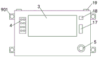
FIG. 2 is a schematic top view of the present invention;
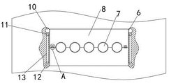
FIG. 3 is a right side schematic view of the sealing plate of the present invention;
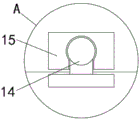
fig. 4 is a schematic view of the structure at a position a of the present invention.
In the drawings, the components represented by the respective reference numerals are listed below:
1. a multimedia platform; 2. supporting legs; 3. a display screen; 4. a control panel; 5. a microphone; 6. a data slot; 7. a data interface; 8. a sealing plate; 9. a lifting moving component; 901. a fixed block; 902. a screw; 903. a universal wheel; 904. rotating the handle; 10. a first gear; 11. a transmission gear; 12. a second gear; 13. a toothed belt; 14. a spherical clamping block; 15. a spherical clamping groove block; 16. a storage drawer; 17. a stylus pen receiving slot; 18. a chalk accommodating groove; 19. a loudspeaker.
Detailed Description
The technical solutions in the embodiments of the present invention will be described clearly and completely with reference to the accompanying drawings in the embodiments of the present invention, and it is obvious that the described embodiments are only some embodiments of the present invention, not all embodiments. Based on the embodiments of the present invention, all other embodiments obtained by a person of ordinary skill in the art without creative efforts belong to the protection scope of the present invention.
Referring to fig. 1-4, the present invention provides a technical solution: a movable lifting auxiliary teaching device for a multimedia classroom comprises a multimedia platform 1, supporting legs 2 are fixed at four corners of the bottom of the multimedia platform 1, stabilizing sheets are fixed at the bottoms of the supporting legs 2, a display screen 3 is arranged in the middle of the top surface of the multimedia platform 1, a control panel 4 is arranged on the left side of the display screen 3, a fixed disk is fixed on the right side of the control panel 4, which is uniformly provided with a plurality of control button display screens 3, a microphone 5 is fixed on the fixed disk, a data slot 6 is arranged on the right side surface of the multimedia platform 1, a plurality of data interfaces 7 are arranged in the data slot 6, sliding slots are arranged on the upper side and the lower side of the data slot 6, a sealing plate 8 is connected in the sliding slots in a sliding mode, a wire slot is arranged at the position, corresponding to the data interface 7, teeth are arranged on two sides of the sealing plate 8, a first gear 10 is meshed with the teeth of, and the bottom is engaged with a transmission gear 11, teeth of a sealing plate 8 positioned below are engaged with a second gear 12, the right sides of the transmission gear 11 and the second gear 12 are both fixed with linkage gears, the two linkage gears are linked through a toothed belt 13, and the left side and the right side of the multimedia platform 1 are provided with lifting moving components 9.
Spherical joint piece 14 and spherical joint groove block 15 that match each other are fixed with respectively on two closing plates 8, through the mutual joint of spherical joint piece 14 and spherical joint groove block 15, can be so that closing plate 8 remain stable.
The lifting moving assembly 9 comprises a fixing block 901, the fixing block 901 is fixedly connected with the multimedia platform 1, the fixing block 901 is in threaded connection with a screw 902, the bottom end of the screw 902 is provided with a universal wheel 903, and the top end of the screw is fixed with a rotating handle 904.
A plurality of storage drawers 16 are arranged on two sides of the bottom of the multimedia platform 1, so that articles can be stored conveniently.
The handwriting pen accommodating groove 17 is formed in the right side of the top face of the multimedia platform 1, the chalk accommodating groove 18 is formed in the top of the handwriting pen accommodating groove 17, and the handwriting pen accommodating groove 17 and the chalk accommodating groove 18 are used for accommodating handwriting pens and chalks.
The speakers 19 are fixed on two sides of the top of the rear side surface of the multimedia platform 1, and the speakers 19 are distributed on two sides of the multimedia platform 1 to transmit sound well.
One specific application of this embodiment is: the rotating handle 904 is rotated to drive the screw 902 to rotate, because the screw 902 is in threaded connection with the fixing block 901, the rotating of the screw 902 can drive the universal wheels 903 to move downwards, each universal wheel 903 is sequentially adjusted to enable the supporting leg 2 to be separated from the bottom surface, the universal wheels 903 support the ground, the multimedia platform 1 can be pushed to move at the moment, after the supporting leg moves to a target position, the rotating handle 904 is rotated reversely, the universal wheels 903 move upwards, and the supporting leg 2 supports the ground again;
when a data line needs to be inserted into the data interface 7, the lower sealing plate 8 is pushed downwards to separate the spherical clamping block 14 from the spherical clamping groove block 15, the lower sealing plate 8 slides downwards to drive the second gear 12 to rotate, the second gear 12 drives the transmission gear 11 to rotate, the transmission gear 11 drives the first gear 10 to rotate, the first gear 10 drives the upper sealing plate 8 to slide upwards, the two sealing plates 8 can be opened oppositely by pushing the sealing plate 8 on one side, the two sealing plates 8 can regularly move oppositely or oppositely through the first gear 10 and the second gear 12, the data line can be accurately clamped, the notch of the data groove 6 is exposed after the sealing plates 8 move upwards and downwards to open, then the data line is inserted, the upper sealing plate 8 is pushed downwards to make the two sealing plates 8 move oppositely, and the data line slot clamps the data line, when sealing up data interface 7, can also fix the data line, prevent that data interface from being touched and being out of shape and not hard up, can play fine guard action.
The utility model discloses display screen 3, control panel 4, microphone 5, speaker 19 that adopt
The utility model provides a background information is given to the cooperation the utility model discloses a description of specification, the technical field personnel of affiliated can reach its use to obtain corresponding result of use, so do not have the one-by-one open.
The utility model provides a product model is only for the use that this technical scheme goes on according to the structural feature of product, and its product can be adjusted and reform transform after purchasing, makes it match more and accord with the utility model belongs to technical scheme, it is the technical scheme of an optimal application of this technical scheme, and the model of its product can be replaced and reform transform according to the technical parameter of its needs, and it is familiar for technical staff that belongs to in the field, consequently, what technical staff that belongs to in the field can be clear passes through the utility model provides a technical scheme obtains corresponding result of use.
In the description herein, references to the description of "one embodiment," "an example," "a specific example," etc., mean that a particular feature, structure, material, or characteristic described in connection with the embodiment or example is included in at least one embodiment or example of the invention. In this specification, the schematic representations of the terms used above do not necessarily refer to the same embodiment or example. Furthermore, the particular features, structures, materials, or characteristics described may be combined in any suitable manner in any one or more embodiments or examples.
The preferred embodiments of the present invention disclosed above are intended only to help illustrate the present invention. The preferred embodiments are not exhaustive and do not limit the invention to the precise embodiments disclosed. Obviously, many modifications and variations are possible in light of the above teaching. The embodiments were chosen and described in order to best explain the principles of the invention and its practical applications, to thereby enable others skilled in the art to best understand the invention for and utilize the invention. The present invention is limited only by the claims and their full scope and equivalents.