CN212839827U - Sectional type drainage pipe - Google Patents
Sectional type drainage pipe Download PDFInfo
- Publication number
- CN212839827U CN212839827U CN202021271696.9U CN202021271696U CN212839827U CN 212839827 U CN212839827 U CN 212839827U CN 202021271696 U CN202021271696 U CN 202021271696U CN 212839827 U CN212839827 U CN 212839827U
- Authority
- CN
- China
- Prior art keywords
- tube
- pipe
- joint ring
- fixedly connected
- lug
- Prior art date
- Legal status (The legal status is an assumption and is not a legal conclusion. Google has not performed a legal analysis and makes no representation as to the accuracy of the status listed.)
- Expired - Fee Related
Links
- 230000037431 insertion Effects 0.000 claims abstract description 17
- 238000003780 insertion Methods 0.000 claims abstract description 17
- 238000007789 sealing Methods 0.000 claims description 18
- 230000003014 reinforcing effect Effects 0.000 claims description 8
- 238000009434 installation Methods 0.000 abstract description 3
- 230000000694 effects Effects 0.000 abstract description 2
- XLYOFNOQVPJJNP-UHFFFAOYSA-N water Substances O XLYOFNOQVPJJNP-UHFFFAOYSA-N 0.000 description 4
- 238000005516 engineering process Methods 0.000 description 3
- 239000011248 coating agent Substances 0.000 description 2
- 238000000576 coating method Methods 0.000 description 2
- 239000000463 material Substances 0.000 description 2
- 229920000915 polyvinyl chloride Polymers 0.000 description 2
- 239000004800 polyvinyl chloride Substances 0.000 description 2
- 238000003466 welding Methods 0.000 description 2
- OKTJSMMVPCPJKN-UHFFFAOYSA-N Carbon Chemical compound [C] OKTJSMMVPCPJKN-UHFFFAOYSA-N 0.000 description 1
- 230000009286 beneficial effect Effects 0.000 description 1
- 239000004568 cement Substances 0.000 description 1
- 230000006835 compression Effects 0.000 description 1
- 238000007906 compression Methods 0.000 description 1
- 230000007797 corrosion Effects 0.000 description 1
- 238000005260 corrosion Methods 0.000 description 1
- 238000010586 diagram Methods 0.000 description 1
- 238000007599 discharging Methods 0.000 description 1
- 239000003822 epoxy resin Substances 0.000 description 1
- 238000001125 extrusion Methods 0.000 description 1
- 239000003292 glue Substances 0.000 description 1
- 229910021389 graphene Inorganic materials 0.000 description 1
- 239000004615 ingredient Substances 0.000 description 1
- 229920000647 polyepoxide Polymers 0.000 description 1
- 239000010865 sewage Substances 0.000 description 1
- 239000002689 soil Substances 0.000 description 1
- 238000005728 strengthening Methods 0.000 description 1
- 239000002351 wastewater Substances 0.000 description 1
Images

Landscapes
- Sink And Installation For Waste Water (AREA)
Abstract
The utility model relates to a sectional type drainage pipe relates to drainage pipe's field, and it includes two at least bodys, the one end fixedly connected with joint ring of body, joint ring and body are concentric setting, a lug of other end fixedly connected with of body, the annular has been seted up on the inside wall of joint ring, the joint ring has been kept away from and has been seted up the insertion groove on the terminal surface of body, insertion groove and annular communicate mutually, the lug of body is in adjacent body insertion groove, the lug joint is in the annular of adjacent body. This application is solved drainage pipe and is received corruption or collision and change inconvenience when damaged, and the higher problem of cost has the installation and dismantles comparatively conveniently, only needs to change this section pipe body, need not whole drainage pipe and changes, practices thrift the effect of cost.
Description
Technical Field
The application relates to the field of drainage pipelines, in particular to a sectional type drainage pipeline.
Background
The drainage pipe refers to a system consisting of a pipe channel for collecting and discharging sewage, wastewater and rainwater and auxiliary facilities thereof, and comprises a main pipe, branch pipes and a pipeline leading to a treatment plant.
The pipe body of the drainage pipeline in the related technology is generally connected by adopting a welding technology, namely, the pipe is cooled after being welded, or a short pipe is directly replaced by a long pipe to realize the water conveying function in a certain section of engineering.
In view of the above-mentioned related technologies, the inventor believes that there is a problem that after welding, the drainage pipe is a whole, the drainage pipe is often buried under the indoor floor, the drainage pipe is easily damaged due to corrosion or extrusion by cement on the indoor floor, once the drainage pipe is damaged, the whole drainage pipe needs to be dug out for replacement, and replacement is inconvenient and cost is high.
SUMMERY OF THE UTILITY MODEL
In order to solve the problem that drainage pipe receives corruption or collision and change inconvenience when damaged, the cost is higher, this application provides a sectional type drainage pipe.
The application provides a sectional type drainage pipe adopts following technical scheme:
the utility model provides a sectional type drainage pipe, includes two at least bodys, the one end fixedly connected with joint ring of body, joint ring and body are concentric setting, another end fixedly connected with lug of body, the annular has been seted up on the inside wall of joint ring, the joint ring has been kept away from and has been seted up the insertion groove on the terminal surface of body, insertion groove and annular communicate mutually, the lug of body is in adjacent body insertion groove, the lug joint is in the annular of adjacent body.
Through adopting above-mentioned technical scheme, the lug of body inserts the back at the annular internal rotation in the insertion groove of adjacent body for the body realizes being connected with another body, and when a certain body was damaged, only need shift out this body through the insertion groove after the annular internal rotation, realize breaking away from of this body and another body, and the installation is comparatively convenient with the dismantlement, only need change this section of body moreover, need not whole drainage pipe and changes, practices thrift the cost.
Preferably, the bottom wall of the ring groove is provided with at least two bulges, and the lug is clamped between the two adjacent bulges.
By adopting the technical scheme, the lug is abutted between the two bulges after rotating in the annular groove, so that the lug is fixed between the two bulges, the relative position between the two adjacent pipe bodies is locked, the lug is not easy to separate from the insertion groove under the non-artificial action, and the connection firmness between the two pipe bodies is improved.
Preferably, the outer tube is sleeved on the outer side wall of the tube body, the outer diameter of the outer tube is equal to that of the clamping ring, the outer tube and the tube body are arranged concentrically, and one end of the outer tube is fixedly connected with one side, close to the tube body, of the clamping ring.
Through adopting above-mentioned technical scheme, fixedly connected with outer tube on the joint ring, the body is lived to the outer tube parcel for the body is difficult for receiving external pollution corruption, and does not influence the use of body when the outer tube breaks, makes the life increase of body.
Preferably, the outer pipe is plated with an anticorrosive layer.
Through adopting above-mentioned technical scheme, scribble the anticorrosive coating on the outer tube for the outer tube is difficult for receiving external pollution corruption, has guaranteed the structural strength of outer tube and body, has increased the life of body.
Preferably, at least one reinforcing strip is fixedly connected to the outer side wall of the pipe body, the reinforcing strip is arranged along the circumferential direction of the pipe body, and one side of the reinforcing strip is fixedly connected with the inner side wall of the outer pipe.
Through adopting above-mentioned technical scheme, the both ends of strengthening the strip are fixed connection respectively on the lateral wall of body and the inside wall of outer tube, have increased the structural strength of body and outer tube, have strengthened the ability of the resistance to pressure and the shear strength of outer tube and inner tube.
Preferably, the clamping ring is further provided with a through hole, the through hole penetrates through two end faces of the clamping ring, and a cavity formed by matching the outer pipe and the pipe body is communicated with the through hole.
Through adopting above-mentioned technical scheme, the cavity that through-hole and outer tube and body cooperation formed communicates each other for when the inner tube was damaged, rivers can flow into next cavity along the cavity that outer tube and body cooperation formed through the through-hole in, rivers are difficult for piling up in the cavity that outer tube and inner tube cooperation formed, thereby make inside water pressure too big and make the water pipe burst, have improved the life of body and outer tube.
Preferably, the outer side wall of the clamping ring is fixedly connected with a sealing tube, one side of the sealing tube extends out of the clamping ring, and the part of the sealing tube extending out of the tube body is sleeved on the outer side wall of the adjacent outer tube.
Through adopting above-mentioned technical scheme, the junction between two bodys is lived in the sealed tube parcel, has increased the leakproofness of connecting between two bodys, has reduced the possibility that rivers flowed from the gap between two bodys, prevents that rivers from flowing the soil property of polluting this department between two bodys.
Preferably, the outer side wall of the outer tube is fixedly connected with a limiting strip, and one side of the limiting strip, which is close to the bump, is provided with a plugging groove for plugging the sealing tube.
Through adopting above-mentioned technical scheme, the sealed tube inserts the joint in the inserting groove for the sealed tube is difficult for breaking away from with the adjacent body be connected, has further increased the leakproofness of connecting between two bodys.
In summary, the present application includes at least one of the following beneficial technical effects:
1. the installation and the disassembly are convenient, and only the section of the pipe body needs to be replaced, so that the whole drainage pipeline does not need to be replaced, and the cost is saved;
2. the two ends of the reinforcing bar are respectively fixedly connected to the outer side wall of the pipe body and the inner side wall of the outer pipe, so that the structural strength of the pipe body and the outer pipe is increased, and the compression resistance and the shear resistance of the outer pipe and the inner pipe are enhanced;
3. the sealed tube inserts the joint in the inserting groove for the sealed tube is difficult for breaking away from with being connected of adjacent body, has further increased the leakproofness of connecting between two bodies.
Drawings
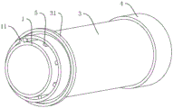
FIG. 1 is a schematic view of a structure of two sectional drainpipes according to a first embodiment of the present application.
Fig. 2 is a schematic structural diagram of a sectional type drainage pipeline according to an embodiment of the present application.
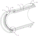
FIG. 3 is a schematic full-sectional view of a sectional type water discharge pipeline according to an embodiment of the present application.
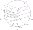
Fig. 4 is an enlarged schematic view of a portion a in fig. 3.
Description of reference numerals: 1. a pipe body; 11. a bump; 2. a snap ring; 21. a ring groove; 22. inserting the groove; 23. a through hole; 24. a protrusion; 3. an outer tube; 31. a limiting strip; 311. inserting grooves; 4. a sealing tube; 5. a reinforcing strip.
Detailed Description
The present application is described in further detail below with reference to figures 1-4.
The embodiment of the application discloses sectional type drainage pipe. Referring to fig. 1 and 2, a sectional type drainage pipe, including body 1, joint ring 2 and outer tube 3, body 1 is the PVC drain pipe, the principal ingredients is polyvinyl chloride, the integrative one end of body 1 that locates of joint ring 2, annular 21 has been seted up on the inside wall of joint ring 2, joint ring 2 has been kept away from and has been seted up insertion groove 22 on the terminal surface of body 1, insertion groove 22 communicates with annular 21 each other, body 1 keeps away from one of joint ring 2 and serves fixedly connected with lug 11, lug 11 is located on the lateral wall of body 1, lug 11 is inserted to annular 21 in through the insertion groove 22 of adjacent body 1, then drive adjacent body 1 and take place relative rotation, make lug 11 joint in annular 21, so that link together two adjacent bodies 1.
An organic whole is equipped with outer tube 3 on the outer lane of joint ring 2, outer tube 3 is concentric setting with body 1, the external diameter of outer tube 3 equals with the external diameter of joint ring 2, fixedly connected with at least one enhancement strip 5 on the inside wall of outer tube 3, the quantity of enhancement strip here is two and more, enhancement strip 5 evenly sets up along the circumference of body, strengthen one side fixed connection that strip 5 kept away from outer tube 3 on body 1 for body 1's structural strength increases.
The outer tube 3 is plated with an anticorrosive coating which can be made of epoxy resin materials or graphene materials, so that the outer tube 3 is not easy to corrode.
Referring to fig. 3 and 4, a sealing tube 4 is bonded and sleeved on the outer side of the clamping ring 2, the inner diameter of the sealing tube 4 is equal to the outer diameter of the clamping ring 2, the sealing tube 4 is bonded on the clamping ring 2 through glue, one end of the sealing tube 4 extends out of the outer side wall of the clamping ring 2, and the part of the sealing tube 4 extending out of the clamping ring 2 is sleeved on the outer side wall of the adjacent outer tube 3 so as to increase the sealing performance when the two adjacent outer tubes 3 are connected; the outer tube 3 is far away from and has spacing 31 on the lateral wall of sealed tube 4, and the inserting groove 311 has been seted up to one side that spacing 31 is close to lug 11, and sealed tube 4 pegs graft in inserting groove 311, has increased the leakproofness when body 1 is connected with body 1.
The inner diameter of the clamping ring 2 far away from the pipe body 1 is the same as the outer diameter of the pipe body 1, the inner diameter of the clamping ring 2 near the pipe body 1 is the same as the inner diameter of the pipe body 1, and the sealing performance of connection between the pipe body 1 and the pipe body 1 is guaranteed.
Still seted up through-hole 23 on the joint ring 2, through-hole 23 runs through the both ends face of joint ring 2, and through-hole 23 is the convex setting with the concentric arc of joint ring 2, and the cavity and the through-hole 23 that outer tube 3 and body 1 cooperation formed communicate with each other for the hydroenergy that falls into in the cavity can flow.
At least two protrusions 24 are arranged on the inner side wall of the ring groove 21, when the bump 11 rotates to a position between the two protrusions 24, the two protrusions 24 are respectively abutted against the bump 11, and the position of the bump 11 in the ring groove 21 is locked.
The implementation principle of a sectional type drainage pipe of the embodiment of the application is as follows: after the convex block 11 on the pipe body 1 is inserted into the insertion groove 22, the sealing pipe 4 is sleeved on the adjacent outer pipe 3, the convex block 11 is embedded in the annular groove 21, the sealing pipe 4 is inserted into the insertion groove 311, and the convex block 11 is positioned between the two protrusions 24 by rotating the convex block 11, so that the connection between the pipe body 1 and the pipe body 1 is realized.
The above embodiments are preferred embodiments of the present application, and the protection scope of the present application is not limited by the above embodiments, so: all equivalent changes made according to the structure, shape and principle of the present application shall be covered by the protection scope of the present application.
Claims (8)
1. A sectional type drainage pipe which is characterized in that: including two at least body (1), the one end fixedly connected with joint ring (2) of body (1), joint ring (2) are concentric setting with body (1), another end fixedly connected with lug (11) of body (1), annular (21) have been seted up on the inside wall of joint ring (2), insertion groove (22) have been seted up on the terminal surface that body (1) was kept away from in joint ring (2), insertion groove (22) communicate with annular (21) each other, lug (11) of body (1) insert in insertion groove (22) through adjacent body (1), lug (11) joint is in annular (21) of adjacent body.
2. The segmented drainline as claimed in claim 1, wherein: at least two bulges (24) are arranged on the bottom wall of the ring groove (21), and the lug (11) is clamped between the two adjacent bulges (24).
3. The segmented drainline as claimed in claim 1, wherein: the outer tube (3) is sleeved on the outer side wall of the tube body (1), the outer diameter of the outer tube (3) is equal to that of the clamping ring (2), the outer tube (3) and the tube body (1) are arranged concentrically, and one end of the outer tube (3) is fixedly connected with one side, close to the tube body (1), of the clamping ring (2).
4. A segmented drainline as claimed in claim 3, wherein: the outer pipe (3) is plated with an anticorrosive layer.
5. A segmented drainline as claimed in claim 3, wherein: the outer pipe is characterized in that at least one reinforcing strip (5) is fixedly connected to the outer side wall of the pipe body (1), the reinforcing strip (5) is arranged along the circumferential direction of the pipe body (1), and one side of the reinforcing strip (5) is fixedly connected with the inner side wall of the outer pipe (3).
6. A segmented drainline as claimed in claim 3, wherein: still seted up through-hole (23) on joint ring (2), through-hole (23) run through the both ends face of joint ring (2), the cavity that outer tube (3) and body (1) cooperation formed communicates with each other through-hole (23).
7. A segmented drainline as claimed in claim 3, wherein: fixedly connected with sealing tube (4) on the lateral wall of joint ring (2), outside joint ring (2) was stretched out to one side of sealing tube (4), part cover that sealing tube (4) stretched out outside body (1) was located on the lateral wall of adjacent outer tube (3).
8. The segmented drainline as claimed in claim 7, wherein: the outer wall of the outer tube (3) is fixedly connected with a limiting strip (31), and one side, close to the convex block (11), of the limiting strip (31) is provided with a plug-in groove (311) for the sealing tube (4) to be plugged in.
Priority Applications (1)
| Application Number | Priority Date | Filing Date | Title |
|---|---|---|---|
| CN202021271696.9U CN212839827U (en) | 2020-07-01 | 2020-07-01 | Sectional type drainage pipe |
Applications Claiming Priority (1)
| Application Number | Priority Date | Filing Date | Title |
|---|---|---|---|
| CN202021271696.9U CN212839827U (en) | 2020-07-01 | 2020-07-01 | Sectional type drainage pipe |
Publications (1)
| Publication Number | Publication Date |
|---|---|
| CN212839827U true CN212839827U (en) | 2021-03-30 |
Family
ID=75180853
Family Applications (1)
| Application Number | Title | Priority Date | Filing Date |
|---|---|---|---|
| CN202021271696.9U Expired - Fee Related CN212839827U (en) | 2020-07-01 | 2020-07-01 | Sectional type drainage pipe |
Country Status (1)
| Country | Link |
|---|---|
| CN (1) | CN212839827U (en) |
Cited By (1)
| Publication number | Priority date | Publication date | Assignee | Title |
|---|---|---|---|---|
| CN113323108A (en) * | 2021-06-04 | 2021-08-31 | 浙江明德建设有限公司 | Inner anchor PE plate composite large-diameter drainage pipeline installation structure and construction method thereof |
-
2020
- 2020-07-01 CN CN202021271696.9U patent/CN212839827U/en not_active Expired - Fee Related
Cited By (1)
| Publication number | Priority date | Publication date | Assignee | Title |
|---|---|---|---|---|
| CN113323108A (en) * | 2021-06-04 | 2021-08-31 | 浙江明德建设有限公司 | Inner anchor PE plate composite large-diameter drainage pipeline installation structure and construction method thereof |
Similar Documents
| Publication | Publication Date | Title |
|---|---|---|
| CN212077674U (en) | High-strength underground drainage system and drainage pipe body connecting structure | |
| CN201502826U (en) | Spigot-and-socket type fusing plastic pipeline | |
| CN210462146U (en) | Circular pipeline repairing structure | |
| CN215568636U (en) | Reinforced concrete pipes with HDPE lining and double sealing joints | |
| CN212273301U (en) | Reinforced concrete pipe of antiseep | |
| CN201347578Y (en) | High-density polyethylene environment-friendly piping shaft | |
| CN205956601U (en) | Internal -rib reinforced polyethylene helical bellows connector | |
| CN113503404A (en) | Reinforced concrete pipeline with HDPE inner lining and double-sealing interface | |
| CN205447078U (en) | Steel is moulded electric smelting of compound pipe and is connected pipe fitting | |
| CN202416361U (en) | Inspection well for improving sealing performance of interface and branch pipe connected with inspection well | |
| CN212251534U (en) | Polyethylene PE helical bellows is strengthened to inner rib | |
| CN212131616U (en) | Municipal drainage pipeline connecting pipe | |
| CN212338438U (en) | Sleeve type internal and external double water-closing flexible connecting device for inspection well | |
| CN212131589U (en) | Water stopping device for jacking pipeline | |
| CN209294629U (en) | A kind of multisection type splicing HDPE drainpipe | |
| CN201330903Y (en) | Bellows joint member | |
| CN221482986U (en) | Straw thermoplastic engineering pipeline | |
| CN201407425Y (en) | Composite corrosion-resistant reinforced concrete drainage pipe | |
| CN223204021U (en) | A concrete pipe with PE lining | |
| CN210566855U (en) | Water delivery pipe with socket type male and female connectors | |
| CN219866744U (en) | Supply and drainage pipe mounting structure with antiseep function | |
| CN218437398U (en) | Permeable drainage pipe fitting | |
| CN212131640U (en) | Pipe gallery | |
| CN214466928U (en) | Connecting structure of drainage pipeline and water collecting well | |
| CN217328922U (en) | Water supply and drainage pipeline anti-seepage device |
Legal Events
| Date | Code | Title | Description |
|---|---|---|---|
| GR01 | Patent grant | ||
| GR01 | Patent grant | ||
| CF01 | Termination of patent right due to non-payment of annual fee |
Granted publication date: 20210330 |
|
| CF01 | Termination of patent right due to non-payment of annual fee |