CN212817071U - Lower limb rehabilitation training robot - Google Patents
Lower limb rehabilitation training robot Download PDFInfo
- Publication number
- CN212817071U CN212817071U CN202020788834.4U CN202020788834U CN212817071U CN 212817071 U CN212817071 U CN 212817071U CN 202020788834 U CN202020788834 U CN 202020788834U CN 212817071 U CN212817071 U CN 212817071U
- Authority
- CN
- China
- Prior art keywords
- lower limb
- running
- rod
- voice coil
- rehabilitation training
- Prior art date
- Legal status (The legal status is an assumption and is not a legal conclusion. Google has not performed a legal analysis and makes no representation as to the accuracy of the status listed.)
- Active
Links
Images


Abstract
The utility model discloses a low limbs rehabilitation training robot relates to rehabilitation apparatus technical field, include: the running device comprises a frame, a running board and a running belt driving component; the lower limb movement device is arranged above the running board, is connected with the rack and comprises a thigh supporting and fixing component, a shank supporting and fixing component, a foot supporting and fixing component and a lower limb movement driving component; the vibrating device is installed below the running board through the vibrating device bottom plate, and the vibrating device bottom plate is provided with a vibrating mechanism which comprises: a slide rail; the sliding block is in sliding fit with the sliding rail; the voice coil motor mounting plate is arranged on the upper side of the sliding block, and a voice coil motor is arranged on the voice coil motor mounting plate; one end of the slide rail is provided with a slide block driving assembly which can drive the slide block to move along the slide rail; the controller is electrically connected with the running belt driving assembly, the lower limb movement driving assembly, the voice coil motor and the sliding block driving assembly; can carry out lower limb bionic simulated exercise rehabilitation training and vibration therapy rehabilitation training on the patient.
Description
Technical Field
The utility model belongs to the technical field of rehabilitation apparatus, more specifically relates to a low limbs rehabilitation training robot.
Background
A large number of clinical medical experiences and theories show that 6 months after the lower limb patient is ill is a recovery golden period, and in the period, besides necessary medicines and operation treatment, a correct and scientific rehabilitation training method plays a very important role in recovering the limb movement function of the patient.
For the lower limb rehabilitation training device, in the design, the path and the standard of the rehabilitation action are firstly determined; the lower limb rehabilitation training device is designed to help patients with lower limb dysfunction to gradually recover walking function, each joint of the lower limb can imitate the coordinated motion of normal people by controlling the moving joints of the lower limb, and the simulation of walking gait of a human body is the core of the lower limb movement form. In order to better exert the rehabilitation training function, the lower limb rehabilitation training device needs to have the functions of simulating normal gait movement of normal people and adjusting the pose of feet besides having a reasonable mechanical structure.
At present, various researches adopt local vibration therapy to treat upper limb dysfunction, and show that the vibration therapy can improve limb movement function, relieve spasm and enhance muscle strength. In clinical treatment, the frequency below 100Hz is used for exciting the neuromuscular tissue, but the local vibration frequency selected by researchers in upper limb rehabilitation treatment is different from 25Hz to 100Hz, and good curative effect is achieved. The vibration therapy has the promotion effect on the increase of the bone density of osteoporosis patients, and the whole body vibration therapy can obviously improve the bone density of postmenopausal women, improve bone pain, increase the muscle strength of patients, improve balance ability and reduce the incidence rate of falling and osteoporosis fracture. The vibration therapy is used as a non-invasive rehabilitation means, can improve the life quality of patients with cardiopulmonary insufficiency and reduce the incidence rate of related complications.
There are some insufficiencies in lower limbs rehabilitation training equipment among the prior art, include: the motion space coupling degree is low, the wearing adaptation is poor, the travelling comfort is poor, structural design is not compact and the rehabilitation structure is single. The existing lower limb rehabilitation training equipment is difficult to stimulate nerve and muscle tissues and relieve spasm, the strength and balance of the lower limb are difficult to improve, the effects of fast and slow muscle strength and endurance of muscle groups are not ideal, the utilization rate of buffer capacity, explosive force and elastic potential energy of muscles is not good, the ideal lower limb rehabilitation purpose of patients is difficult to achieve, and the equipment is also difficult to be applied to diversified fields in various ages and athletes.
SUMMERY OF THE UTILITY MODEL
The utility model aims to provide a lower limb rehabilitation training robot which can perform bionic simulation lower limb movement rehabilitation training on lower limb patients by combining a running device with a lower limb movement device for use, aiming at the defects in the prior art; meanwhile, the lower limb rehabilitation training device is provided with a vibrating device, so that the lower limb of a patient can be subjected to vibration therapy in the training process, and the lower limb rehabilitation effect of the patient is improved.
In order to achieve the above object, the utility model provides a lower limbs rehabilitation training robot, include:
the running device comprises a frame, a running board and a running belt driving component;
the lower limb movement device is arranged above the running board, is connected with the rack, and comprises a thigh supporting and fixing component, a shank supporting and fixing component, a foot supporting and fixing component and a lower limb movement driving component;
the vibrating device is installed through the vibrating device bottom plate run the below of board, be provided with vibration mechanism on the vibrating device bottom plate, vibration mechanism includes:
a slide rail;
the sliding block is in sliding fit with the sliding rail;
the voice coil motor mounting plate is arranged on the upper side of the sliding block, and a voice coil motor is arranged on the voice coil motor mounting plate;
a sliding block driving assembly is arranged at one end of the sliding rail and can drive the sliding block to move along the sliding rail;
and the controller is electrically connected with the running belt driving assembly, the lower limb movement driving assembly, the voice coil motor and the slider driving assembly.
Optionally, the treadmill belt drive assembly comprises:
the running belt is annular and is sleeved on the driving shaft and the driven shaft;
the first belt pulleys are arranged at two ends of the driving shaft;
the servo motor is arranged at the lower end of the rack, a second belt pulley is arranged at the output end of the rack, the second belt pulley is in transmission connection with the first belt pulley through a transmission belt, and the servo motor is electrically connected with the controller.
Optionally, the thigh support securing assembly comprises:
one end of the cross beam is hinged with the rack;
one end of the thigh supporting rod is hinged with the other end of the cross beam, and the thigh supporting rod is a telescopic rod;
the thigh fixing part is arranged on one side of the thigh supporting rod, and a first binding band is arranged on the thigh fixing part;
the shank support and fixation assembly comprises:
one end of the shank support rod is hinged with the other end of the thigh support rod, and the shank support rod is a telescopic rod;
the shank fixing part is arranged on one side of the shank supporting rod, and a second binding band is arranged on the shank fixing part;
the foot supporting and fixing assembly comprises:
the pedal is provided with a connecting part at one side, and the connecting part is hinged with the other end of the shank supporting rod;
and a third strap disposed on the upper side of the pedal.
Optionally, the lower limb movement drive assembly comprises:
one end of the first electric telescopic rod is hinged with the cross beam, and the other end of the first electric telescopic rod is hinged with the thigh supporting rod;
one end of the second electric telescopic rod is hinged with the thigh supporting rod, and the other end of the second electric telescopic rod is hinged with the shank supporting rod;
the first electric telescopic rod and the second electric telescopic rod are electrically connected with the controller.
Optionally, the vibrating mechanism is provided with two, the slide rail passes through the mounting panel to be installed on the vibrating device bottom plate, the one end of mounting panel is provided with the limiting plate, be provided with travel switch on the limiting plate, travel switch with controller electric connection.
Optionally, the slider drive assembly comprises:
the first double-shaft motor is arranged on the mounting plate and is electrically connected with the controller;
the input ends of the two right-angle speed reducers are connected with the output end of the first double-shaft motor;
one end of the screw rod is connected with the output end of the right-angle speed reducer, the other end of the screw rod is rotatably connected with a screw rod seat, and the screw rod seat is installed on the installation plate;
the screw thread seat is internally provided with a screw thread through hole, the screw thread seat is sleeved on the screw rod, and the upper end of the screw thread seat is connected with the voice coil motor mounting plate.
Optionally, the voice coil motor mounting panel with be provided with lifting unit between the slider, lifting unit includes:
the second double-shaft motor is arranged on the upper side of the sliding block;
and the two ball screw lifters are arranged on the threaded seat, the input end of each ball screw lifter is connected with the output end of the second double-shaft motor, and the output end of each ball screw lifter is connected with the voice coil motor mounting plate.
Optionally, the vibration device further comprises a plurality of springs, one end of each spring is connected with the bottom plate of the vibration device, and the other end of each spring is in contact with the running plate.
Optionally, the rack comprises:
the bottom frame is connected with the running board;
the lower end of the inclined bracket is connected with the underframe, and the upper end of the inclined bracket inclines towards the direction close to the running board;
the connecting fixing plate is connected with the upper end of the inclined bracket;
the armrests are arranged on two sides of the upper end of the inclined bracket, and one end of the armrests is connected with the inclined bracket;
and rollers with locks are arranged on the lower sides of the underframe and the running plate.
Optionally, one side of the rack is provided with a connecting rod, one end of the connecting rod is connected with the connecting and fixing plate, the other end of the connecting rod is provided with a control panel, and the controller is arranged in the control panel.
The utility model provides a low limbs rehabilitation training robot, its beneficial effect lies in:
1. the robot is provided with a running device and a lower limb movement device, wherein the lower limb movement device supports and fixes the lower limb of a patient through a thigh supporting and fixing component, a shank supporting and fixing component and a foot supporting and fixing component, drives the lower limb movement device to drive the lower limb of the patient to perform bionic movement training through a lower limb movement driving component, and is matched with the running device to enable the patient to simulate the movement state during normal walking on a running board, so that the rehabilitation training of the lower limb is realized;
2. the thigh supporting rod and the shank supporting rod of the robot are both telescopic rod structures, the length of the telescopic rod structures is adjustable, the telescopic rod structures can be suitable for different patients, and the rehabilitation exercise of the patients is assisted through the movement of hip joints, knee joints and ankle joints;
3. the robot is provided with a vibrating device, the rehabilitation principle of vibration training is utilized, a voice coil motor generates vertical up-and-down vibration, the voice coil motor is driven to move under a running plate through a slider driving assembly, vibration sources can be provided at different positions, the use requirements of different patients are met, the application of a first double-shaft motor and a double-screw rod greatly improves the diversified resonance frequency generated by the vibration sources, the mechanical vibration is more saturated and comfortable by fully utilizing a motion coupling space, the muscle excitability can be activated to the maximum extent by the vibration motion therapy of the resonance frequency, the vibration stimulation and the inherent frequency of muscles reach a resonance state, the muscle contraction efficiency is improved, the muscles and joints of the patients are exercised, the normal activities of the joints and the muscles are gradually recovered, and finally the patients are recovered; and the vibrating device can reduce the probability of delayed lower limb muscle soreness, obviously reduce the delayed muscle soreness degree, vibrate the adipose tissues of the whole body, play a certain energy consumption role on the organism, increase the blood flow under the skin and promote the cell metabolism capability. The vertical vibration training may have a positive effect on preventing aging and osteoporosis, and can more rapidly improve the change of the joint movement range caused by delayed lower limb muscular soreness;
4. compared with static stretching or vibration-free foam rolling, the robot can combine vibration training and bionic lower limb movement training, increases the range of joint movement, improves the training effect, and is also suitable for application in diversified fields of various age groups and athletes wounded;
5. the robot is provided with two vibration mechanisms which can work alternately, so that vibration waves can be generated continuously, a patient cannot feel pause and frustration, and the vibration mechanisms can move linearly and reciprocally, so that the vibration effect is improved;
6. the robot is provided with a control panel and a control unit, can conveniently set a motion training mode through the control panel, and is simple and convenient to operate.
Other features and advantages of the present invention will be described in detail in the detailed description which follows.
Drawings
The above and other objects, features and advantages of the present invention will become more apparent by describing in more detail exemplary embodiments thereof with reference to the attached drawings, in which like reference numerals generally represent like parts throughout the exemplary embodiments of the present invention.
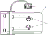
Fig. 1 shows a three-dimensional structure diagram of a lower limb rehabilitation training robot according to an embodiment of the present invention.
Fig. 2 shows a schematic front view of a lower limb rehabilitation training robot according to an embodiment of the present invention.
Fig. 3 shows a schematic side view of a lower limb rehabilitation training robot according to an embodiment of the present invention.
Fig. 4 shows a schematic top view of a lower limb rehabilitation training robot according to an embodiment of the present invention.
Fig. 5 is a schematic three-dimensional structure diagram of a running device of a lower limb rehabilitation training robot according to an embodiment of the present invention.
Fig. 6 shows a three-dimensional structure diagram of a running belt driving assembly of a lower limb rehabilitation training robot according to an embodiment of the present invention.
Fig. 7 is a schematic view showing an angle of the lower limb movement device of the lower limb rehabilitation training robot according to an embodiment of the present invention.
Fig. 8 is a schematic three-dimensional structure diagram of another angle of the lower limb movement device of the lower limb rehabilitation training robot according to an embodiment of the present invention.
Fig. 9 is a schematic three-dimensional structure diagram of a vibration device of a lower limb rehabilitation training robot according to an embodiment of the present invention.
Fig. 10 is a schematic three-dimensional structure diagram of a vibration mechanism of a lower limb rehabilitation training robot according to an embodiment of the present invention.
Fig. 11 is a schematic top view of a vibrating mechanism of a lower limb rehabilitation training robot according to an embodiment of the present invention.
Fig. 12 is a schematic three-dimensional structure diagram of a lifting assembly of a lower limb rehabilitation training robot according to an embodiment of the present invention.
Description of reference numerals:
1. a running device; 2. a frame; 3. running board, 4, running belt; 5. a lower limb movement device; 6. a vibrating device; 7. a vibrating device base plate; 8. a vibration mechanism; 9. a slide rail; 10. a slider; 11. a voice coil motor mounting plate; 12. a voice coil motor; 13. a drive shaft; 14. a driven shaft; 15. a first pulley; 16. a servo motor; 17. a second pulley; 18. a drive belt; 19. a cross beam; 20. a thigh support bar; 21. a thigh fixing part; 22. a first strap; 23. a shank support bar; 24. a shank securing portion; 25. a second strap; 26. a pedal; 27. a connecting portion; 28. a third strap; 29. a first electric telescopic rod; 30. a second electric telescopic rod; 31. mounting a plate; 32. a limiting plate; 33. a travel switch; 34. a first dual-axis motor; 35. a right-angle reducer; 36. a screw rod; 37. a spring; 38. a chassis; 39. a tilting bracket; 40. connecting the fixed plate; 41. a handrail; 42. a roller with a lock; 43. a connecting rod; 44. a control panel; 45. a screw base; 46. a threaded seat; 47. a second dual-shaft motor; 48. ball screw elevator.
Detailed Description
Preferred embodiments of the present invention will be described in more detail below. While the following describes preferred embodiments of the present invention, it should be understood that the present invention may be embodied in various forms and should not be construed as limited to the embodiments set forth herein. Rather, these embodiments are provided so that this disclosure will be thorough and complete, and will fully convey the scope of the invention to those skilled in the art.
The utility model provides a low limbs rehabilitation training robot, include:
the running device comprises a frame, a running board and a running belt driving component;
the lower limb movement device is arranged above the running board, is connected with the rack and comprises a thigh supporting and fixing component, a shank supporting and fixing component, a foot supporting and fixing component and a lower limb movement driving component;
the vibrating device is installed below the running board through the vibrating device bottom plate, and the vibrating device bottom plate is provided with a vibrating mechanism which comprises:
a slide rail;
the sliding block is in sliding fit with the sliding rail;
the voice coil motor mounting plate is arranged on the upper side of the sliding block, and a voice coil motor is arranged on the voice coil motor mounting plate;
one end of the slide rail is provided with a slide block driving assembly which can drive the slide block to move along the slide rail;
and the controller is electrically connected with the running belt driving assembly, the lower limb movement driving assembly, the voice coil motor and the slider driving assembly.
Specifically, the running plate is connected to the lower end of the frame, and the running belt driving assembly can drive the running belt to move on the running plate, so that the function of the running machine is realized; the lower limb movement device supports and fixes thighs, calves and feet of a patient through the thigh supporting and fixing component, the calf supporting and fixing component and the foot supporting and fixing component respectively, so that the patient can stand on the running board under the supporting action of the lower limb movement device, then the thigh supporting and fixing component, the calf supporting and fixing component and the foot supporting and fixing component are driven to perform bionic movement through the lower limb movement driving component, and then the lower limbs of the patient are driven to perform walking simulation training, and lower limb rehabilitation training of the patient is achieved; the vibrating device generates regular 20Hz mechanical vibration along the radial direction through the voice coil motor, the vibration is transmitted to the lower limbs of a patient through the running plate and the running belt, the effect of the vibration exercise therapy depends on the frequency, amplitude and time range combination of the vibration, the muscle shuttle activity causing the stretch reflex can be increased, and the rapid change of the muscle length can be caused. The local vibration can improve the input of deep and shallow feeling of hemiparalysis side, and the increase of the feeling input can improve the motor function ability and the daily life activity ability; the respective operable components of the robot can be controlled by a controller.
Optionally, the running belt drive assembly comprises:
the driving shaft and the driven shaft are respectively arranged at two ends of the running plate, the running belt is annular and is sleeved on the driving shaft and the driven shaft;
the first belt pulleys are arranged at two ends of the driving shaft;
the servo motor is arranged at the lower end of the rack, a second belt pulley is arranged at the output end of the servo motor and is in transmission connection with the first belt pulley through a transmission belt, and the servo motor is electrically connected with the controller.
Alternatively, the servo motor is a brushless dc servo motor, the rotational speed of which can be controlled by a controller.
Optionally, both ends of the driving shaft and the driven shaft are provided with deep groove ball bearings, and the driving shaft and the driven shaft are rotatably connected with the mounting brackets on both sides of the running plate through the deep groove ball bearings.
Specifically, servo motor drives the second belt pulley and rotates, and the second belt pulley passes through belt transmission and drives first belt pulley and rotate, and then drives the driving shaft and rotate, and the action wheel makes the running belt remove on running the board with the cooperation from the driving wheel, realizes the effect of treadmill.
Optionally, the thigh support securing assembly comprises:
one end of the beam is hinged with the frame;
one end of the thigh supporting rod is hinged with the other end of the cross beam, and the thigh supporting rod is a telescopic rod;
the thigh fixing part is arranged on one side of the thigh supporting rod, and a first binding band is arranged on the thigh fixing part;
the shank support and fixation assembly comprises:
one end of the shank support rod is hinged with the other end of the thigh support rod, and the shank support rod is a telescopic rod;
the shank fixing part is arranged on one side of the shank supporting rod, and a second binding band is arranged on the shank fixing part;
the foot supports the fixed subassembly and includes:
the pedal is provided with a connecting part at one side, and the connecting part is hinged with the other end of the shank supporting rod;
and the third binding band is arranged on the upper side of the pedal.
Optionally, the middle of the rack is provided with an installation beam, the cross beam is hinged to the installation beam, and the installation beam is connected with the rack in a sliding mode, so that height adjustment of the installation beam can be achieved.
Specifically, the cross beam is hinged with the frame, so that the weight of a patient can act on the running board after the patient fixes the lower limbs on the lower limb movement device, and the vibration device below the running board can transmit vibration to the lower limbs of the patient so as to treat the lower limbs of the patient by adopting vibration therapy; the thigh fixing part and the shank fixing part are both in a groove shape, so that a patient can place a thigh and a shank in the thigh fixing part and the shank fixing part respectively, the thigh fixing part and the shank fixing part are fixed through the first bandage and the second bandage, and the foot part can be fixed on the pedal through the third bandage, so that the positioning of the lower limb is realized; thigh bracing piece and shank bracing piece can support patient's big or small leg for the patient can stand on running the board, and thigh bracing piece and shank bracing piece are the telescopic link, can realize length adjustment, use and the patient of different heights and leg length uses.
Optionally, the lower limb movement drive assembly comprises:
one end of the first electric telescopic rod is hinged with the cross beam, and the other end of the first electric telescopic rod is hinged with the thigh supporting rod;
one end of the second electric telescopic rod is hinged with the thigh supporting rod, and the other end of the second electric telescopic rod is hinged with the shank supporting rod;
the first electric telescopic rod and the second electric telescopic rod are electrically connected with the controller.
Specifically, because the bending/stretching motion of the lower limbs of the human body on the sagittal plane is the main motion, each leg has 3 degrees of freedom which are respectively hip joint stretching/bending, knee joint stretching/bending and ankle joint stretching/bending, and the cross beam has a certain length to ensure that leg motion components have enough coupling space and relatively accord with the situation that the hip joint is used as the center when the legs are lifted by the standing posture of the human body; a U-shaped support is arranged on the lower side of the cross beam, the first electric telescopic rod is hinged with the U-shaped support, the other end of the first electric telescopic rod is hinged with the thigh supporting rod through the U-shaped support, and the extension and retraction of the first electric telescopic rod can drive the thigh supporting and fixing assembly to rotate relative to the cross beam, so that the hip joint of the patient is driven to rotate, and the leg lifting action of the patient during walking is simulated; similarly, the second electric telescopic rod can drive the shank support fixing rod to rotate relative to the thigh support fixing rod, so as to drive the patient to realize the knee bending action; rolling bearings are arranged at the hinged points between the cross beam and the thigh supporting rod, between the thigh supporting rod and the shank supporting rod, and between the shank supporting rod and the pedal, so that the interchangeability is good; the lower limb movement device can enable the shank of a patient with leg disability to move along the linear direction, and has the function of exercise physiology stretching training.
Optionally, the vibrating mechanism is provided with two, and the slide rail passes through the mounting panel to be installed on the vibrating device bottom plate, and the one end of mounting panel is provided with the limiting plate, is provided with travel switch on the limiting plate, travel switch and controller electric connection.
Specifically, two vibrating mechanism set up on the vibrating device bottom plate along the moving direction of running area, and one side that two vibrating mechanism are close to each other is provided with the limiting plate on the mounting panel, and the mounting height of voice coil motor mounting panel on the slider cooperatees with travel switch's mounting height on the limiting plate, and one side that the voice coil motor mounting panel is close to travel switch is provided with the bellying, and the bellying can promote travel switch when the voice coil motor mounting panel removes to the limiting plate, through controller control slider stop movement.
Optionally, a metal damper is disposed between the voice coil motor and the voice coil motor mounting plate.
Specifically, the metal damper is used for avoiding the influence of bad vibration generated by rigid connection between the voice coil motor and the voice coil motor mounting plate on other structural components.
The slide rail arranged between the two screw rods is arranged on the mounting plate, so that the bearing effect is achieved, and the guide effect of stably correcting the linear movement of the slide block is achieved.
Optionally, the slider drive assembly comprises:
the first double-shaft motor is arranged on the mounting plate and is electrically connected with the controller;
the input ends of the two right-angle speed reducers are connected with the output end of the first double-shaft motor;
one end of the screw rod is connected with the output end of the right-angle speed reducer, the other end of the screw rod is rotatably connected with a screw rod seat, and the screw rod seat is installed on the installation plate;
the screw thread seat is internally provided with a screw thread through hole, the screw thread seat is sleeved on the screw rod, and the upper end of the screw thread seat is connected with the voice coil motor mounting plate.
Specifically, the first double-shaft motor mainly performs a linear motion driving effect, and the screw rod is driven to rotate by the two-in-one mode through the two right-angle accelerators, so that the two screw seats and the synchronism of the movement of the two ends of the voice coil motor mounting plate on the screw seats are ensured, and the voice coil motor can uniformly transmit vibration waves in the axial direction; screw hole cooperation in lead screw and the screw thread seat drives the voice coil motor mounting panel and removes along the slide rail, and then drives the voice coil motor and remove, and first double-shaft motor can drive whole slider and remove for the voice coil motor can be to the different positions transmission vibration of race board, makes the patient can both obtain the vibration training in the motion mode of various differences and each motion region.
Optionally, a bearing roller is arranged on the mounting plate, the bearing roller is mounted on the mounting plate through a U-shaped bracket, and a deep groove ball bearing is arranged between a roller shaft of the bearing roller and the U-shaped bracket.
Specifically, the setting of bearing gyro wheel can move with the roll cooperation of voice coil motor mounting panel when bearing gyro wheel top at the voice coil motor mounting panel, improves the bearing effect.
Optionally, the voice coil motor mounting panel with be provided with lifting unit between the slider, lifting unit includes:
the second double-shaft motor is arranged on the upper side of the sliding block;
and the two ball screw lifters are arranged on the threaded seat, the input end of each ball screw lifter is connected with the output end of the second double-shaft motor, and the output end of each ball screw lifter is connected with the voice coil motor mounting plate.
Specifically, the second double-shaft motor can drive the voice coil motor mounting plate and the voice coil motor to lift through the ball screw lifter, so that the output end of the voice coil motor is prevented from rubbing against the running plate when the voice coil motor moves, and damage is avoided; when the slider driving assembly drives the slider and the voice coil motor to move along the sliding rail, the voice coil motor is located at an initial position, a gap is reserved between the output end of the voice coil motor and the running plate, after the voice coil motor is started, the second double-shaft motor is started, the voice coil motor is driven to ascend through the ball screw elevator, the output end of the voice coil motor is in contact with the lower side of the running plate, vibration is transmitted to the running plate, and vibration is achieved; two vibration mechanism alternate operation, simultaneously, slider actuating mechanism and lifting unit cooperation operation in two vibration mechanisms, a vibration mechanism's voice coil motor during operation, another vibration mechanism's voice coil motor only removes and does not start, and the two goes on in turn, provides the vibration on the different positions of running the board for the vibration is continuous, and the user can not experience and feel immediately, and the patient can both obtain the vibration therapy training in various different motion modes and each motion region.
Optionally, the vibrating device further comprises a plurality of springs, one end of each spring is connected with the vibrating device bottom plate, and the other end of each spring is in contact with the running plate.
Specifically, the springs are uniformly distributed on two sides of the vibration mechanism to play a role in uniformly assisting vibration.
Optionally, the rack comprises:
the bottom frame is connected with the running board;
the lower end of the inclined bracket is connected with the underframe, and the upper end of the inclined bracket inclines towards the direction close to the running board;
the connecting fixing plate is connected with the upper end of the inclined bracket;
the armrests are arranged on two sides of the upper end of the inclined bracket, and one end of the armrests is connected with the inclined bracket;
the lower sides of the chassis and the running plate are provided with rollers with locks.
Specifically, an included angle of 15 degrees is formed between the inclined bracket and the vertical surface of the underframe, and the driving shaft drives the running belt to move through rolling friction; the patient fixes the lower limbs in the lower limb movement device, stands on the running board, sets the rotating speed of the servo motor through the controller, controls the two brushless DC servo motors to drive the driving shaft to rotate, the running belt rolls to generate forward static friction with the pedal of the patient foot to enable the patient foot to generate gait movement, the ankle joint rotates to drive the shank to generate movement, and the first electric telescopic rod and the second electric telescopic rod are matched with the extension and retraction to drive the thigh and the shank of the patient to move, so as to realize bionic gait training; during training, the patient can keep body balance through the handrails, and the fear psychology is overcome.
Optionally, one side of the rack is provided with a connecting rod, one end of the connecting rod is connected with the connecting fixing plate, the other end of the connecting rod is provided with a control panel, and the controller is arranged in the control panel.
Specifically, the control panel is provided with an operation button and/or a display screen, and a user can set and adjust the operation mode of the robot through the control panel.
Examples
As shown in fig. 1 to 12, the utility model provides a lower limb rehabilitation training robot, including:
the running device 1 comprises a frame 2, a running board 3, a running belt 4 and a running belt driving component;
the lower limb movement device 5 is arranged above the running board 3, is connected with the rack 2, and comprises a thigh supporting and fixing component, a shank supporting and fixing component, a foot supporting and fixing component and a lower limb movement driving component;
vibrating device 6 is installed in the below of running board 3 through vibrating device bottom plate 7, is provided with vibration mechanism 8 on vibrating device bottom plate 7, and vibration mechanism 8 includes:
a slide rail 9;
the sliding block 10 is in sliding fit with the sliding rail 9;
the voice coil motor mounting plate 11 is arranged on the upper side of the slider 10, and a voice coil motor 12 is arranged on the voice coil motor mounting plate 11;
one end of the slide rail 9 is provided with a slide block driving component which can drive the slide block 10 to move along the slide rail 9;
and the controller is electrically connected with the running belt driving assembly, the lower limb movement driving assembly, the voice coil motor 12 and the sliding block driving assembly.
In this embodiment, the running belt driving assembly includes:
the driving shaft 13 and the driven shaft 14 are respectively arranged at two ends of the running plate 3, the running belt 4 is annular, and the running belt 4 is sleeved on the driving shaft 13 and the driven shaft 14;
first belt pulleys 15 provided at both ends of the driving shaft 13;
the servo motor 16 is arranged at the lower end of the rack 2, a second belt pulley 17 is arranged at the output end, the second belt pulley 17 is in transmission connection with the first belt pulley 15 through a transmission belt 18, and the servo motor 16 is electrically connected with the controller.
In this embodiment, the thigh support fixing assembly includes:
one end of the beam 19 is hinged with the frame 2;
one end of the thigh supporting rod 20 is hinged with the other end of the cross beam 19, and the thigh supporting rod 20 is a telescopic rod;
a thigh fixing part 21 provided at one side of the thigh support bar 20, the thigh fixing part 21 being provided with a first strap 22;
the shank support and fixation assembly comprises:
one end of the shank support rod 23 is hinged with the other end of the thigh support rod 20, and the shank support rod 23 is a telescopic rod;
a shank fixing part 24 arranged at one side of the shank support bar 23, the shank fixing part 24 being provided with a second strap 25;
the foot supports the fixed subassembly and includes:
a pedal 26, wherein one side of the pedal 26 is provided with a connecting part 27, and the connecting part 27 is hinged with the other end of the shank support rod 23;
and a third strap 28 provided on the upper side of the pedal 26.
In this embodiment, the lower limb movement drive assembly includes:
one end of the first electric telescopic rod 29 is hinged with the cross beam 19, and the other end is hinged with the thigh supporting rod 20;
one end of the second electric telescopic rod 30 is hinged with the thigh supporting rod 20, and the other end is hinged with the shank supporting rod 23;
the first electric telescopic rod 29 and the second electric telescopic rod 30 are electrically connected with the controller.
In this embodiment, two vibration mechanisms 8 are provided, the slide rail 9 is mounted on the bottom plate 7 of the vibration device through a mounting plate 31, one end of the mounting plate 31 is provided with a limit plate 32, a travel switch 33 is arranged on the limit plate 32, and the travel switch 33 is electrically connected with the controller.
In this embodiment, the slider driving assembly includes:
the first double-shaft motor 34 is arranged on the mounting plate 31 and is electrically connected with the controller;
two right-angle reducers 35, the input ends of which are connected with the output end of the first double-shaft motor 34;
one end of the screw rod 36 is connected with the output end of the right-angle reducer 35, the other end of the screw rod is rotatably connected with a screw rod seat 45, and the screw rod seat 45 is installed on the installation plate 31;
the screw thread seat 46 is internally provided with a screw thread through hole, the screw thread seat 46 is sleeved on the screw rod 36, and the upper end of the screw thread seat 46 is connected with the voice coil motor mounting plate 11.
Optionally, a lifting assembly is disposed between the voice coil motor mounting plate 11 and the slider 10, and the lifting assembly includes:
a second double shaft motor 47 provided on the upper side of the slider 10;
and the two ball screw lifters 48 are arranged on the threaded seat 46, the input ends of the two ball screw lifters are connected with the output end of the second double-shaft motor 47, and the output end of the two ball screw lifters is connected with the voice coil motor mounting plate 11.
In this embodiment, the vibration device further includes a plurality of springs 37, one end of each spring 37 is connected to the vibration device bottom plate 7, and the other end of each spring 37 is in contact with the running board 3.
In the present embodiment, the chassis 2 includes:
the bottom frame 38 is connected with the running board 3;
a tilting bracket 39 having a lower end connected to the base frame 38, and an upper end of the tilting bracket 39 being tilted in a direction approaching the running board 3;
a connection fixing plate 40 connected to the upper end of the inclined bracket 39;
the under frame 38 and the underside of the running board 3 are provided with rollers 42 with locks.
In this embodiment, a connecting rod 43 is disposed on one side of the frame 2, one end of the connecting rod 43 is connected to the connecting and fixing plate 40, the other end is disposed with a control panel 44, and the controller is disposed in the control panel 44.
To sum up, the utility model provides a during lower limbs rehabilitation training robot used, the patient stepped on footboard 26 with the foot, fixed the foot on footboard 26 through third bandage 28, placed thigh and shank respectively in thigh fixed part 21 and shank fixed part 24, can fix patient's thigh and shank through first bandage 22 and second bandage 25, and the bandage is flexible bandage, can improve the travelling comfort. The running mode of the robot can be set through the control panel 44, after the robot is started, the controller starts the running device 1 and the lower limb movement device 5 according to the set running mode, the servo motor 16 rotates, the driving shaft 13 is driven to rotate through the driving belt 18, and the running belt 4 is driven to move; meanwhile, the lower limb moving device 5 and the running belt 4 move in a matched manner, the first electric telescopic rod 29 and the second electric telescopic rod 30 drive the hip joint and the knee joint of the patient to rotate through expansion and contraction, so that the lower limb of the patient is driven to perform bionic simulated walking, the friction between the pedal 26 and the running belt 4 enables the running belt 4 to drive the foot of the patient to move along with the running belt 4, the rotation of the ankle part is realized, and the movement of the lower limb of the patient is enabled to accord with the normal walking gait; the lower limbs of the patient are subjected to walking rehabilitation training. At this moment, can also start vibrating device 6, provide the vibration source through the start-up of voice coil motor 12, voice coil motor 12 passes through lifting unit height-adjusting for its output contacts with running board 3, with vibration transmission to running board, and rethread running belt 4 and footboard 26 transmit patient's low limbs, implement the vibration therapy to patient's low limbs, improve limbs motion function, alleviate the spasm, strengthen muscle strength, help the recovery of patient's low limbs.
In other embodiments of the present invention, one or two of the running device 1, the lower limb exercise device 5 and the vibration device 6 can be selectively used according to the needs of the patient to perform targeted rehabilitation training on the patient, such as: the running device 1 and the lower limb movement device 5, the running device 1 and the vibration device 6 or the lower limb movement device 5 and the vibration device 6 can be used for stationary phase rehabilitation therapy, and the vibration device 6 can be used alone for vibration therapy or posture relaxation before or after rehabilitation training of a patient. The lower limb rehabilitation training robot is convenient to operate, flexible to use and suitable for patients with lower limb movement dysfunction to perform rehabilitation training.
While various embodiments of the present invention have been described above, the above description is intended to be illustrative, not exhaustive, and not limited to the disclosed embodiments. Many modifications and variations will be apparent to those of ordinary skill in the art without departing from the scope and spirit of the described embodiments.
Claims (10)
1. A lower limb rehabilitation training robot, comprising:
the running device comprises a frame, a running board and a running belt driving component;
the lower limb movement device is arranged above the running board, is connected with the rack, and comprises a thigh supporting and fixing component, a shank supporting and fixing component, a foot supporting and fixing component and a lower limb movement driving component;
the vibrating device is installed through the vibrating device bottom plate run the below of board, be provided with vibration mechanism on the vibrating device bottom plate, vibration mechanism includes:
a slide rail;
the sliding block is in sliding fit with the sliding rail;
the voice coil motor mounting plate is arranged on the upper side of the sliding block, and a voice coil motor is arranged on the voice coil motor mounting plate;
a sliding block driving assembly is arranged at one end of the sliding rail and can drive the sliding block to move along the sliding rail;
and the controller is electrically connected with the running belt driving assembly, the lower limb movement driving assembly, the voice coil motor and the slider driving assembly.
2. The lower extremity rehabilitation training robot of claim 1, wherein said tread belt drive assembly comprises:
the running belt is annular and is sleeved on the driving shaft and the driven shaft;
the first belt pulleys are arranged at two ends of the driving shaft;
the servo motor is arranged at the lower end of the rack, a second belt pulley is arranged at the output end of the rack, the second belt pulley is in transmission connection with the first belt pulley through a transmission belt, and the servo motor is electrically connected with the controller.
3. The lower extremity rehabilitation training robot of claim 1, wherein said thigh support fixture assembly comprises:
one end of the cross beam is hinged with the rack;
one end of the thigh supporting rod is hinged with the other end of the cross beam, and the thigh supporting rod is a telescopic rod;
the thigh fixing part is arranged on one side of the thigh supporting rod, and a first binding band is arranged on the thigh fixing part;
the shank support and fixation assembly comprises:
one end of the shank support rod is hinged with the other end of the thigh support rod, and the shank support rod is a telescopic rod;
the shank fixing part is arranged on one side of the shank supporting rod, and a second binding band is arranged on the shank fixing part;
the foot supporting and fixing assembly comprises:
the pedal is provided with a connecting part at one side, and the connecting part is hinged with the other end of the shank supporting rod;
and a third strap disposed on the upper side of the pedal.
4. The lower limb rehabilitation training robot of claim 3, wherein the lower limb movement drive assembly comprises:
one end of the first electric telescopic rod is hinged with the cross beam, and the other end of the first electric telescopic rod is hinged with the thigh supporting rod;
one end of the second electric telescopic rod is hinged with the thigh supporting rod, and the other end of the second electric telescopic rod is hinged with the shank supporting rod;
the first electric telescopic rod and the second electric telescopic rod are electrically connected with the controller.
5. The lower limb rehabilitation training robot as claimed in claim 1, wherein the number of the vibration mechanisms is two, the slide rails are mounted on the bottom plate of the vibration device through a mounting plate, one end of the mounting plate is provided with a limiting plate, a travel switch is arranged on the limiting plate, and the travel switch is electrically connected with the controller.
6. The lower extremity rehabilitation training robot of claim 5, wherein said slider drive assembly comprises:
the first double-shaft motor is arranged on the mounting plate and is electrically connected with the controller;
the input ends of the two right-angle speed reducers are connected with the output end of the first double-shaft motor;
one end of the screw rod is connected with the output end of the right-angle speed reducer, the other end of the screw rod is rotatably connected with a screw rod seat, and the screw rod seat is installed on the installation plate;
the screw thread seat is internally provided with a screw thread through hole, the screw thread seat is sleeved on the screw rod, and the upper end of the screw thread seat is connected with the voice coil motor mounting plate.
7. The lower limb rehabilitation training robot of claim 6, wherein a lifting assembly is arranged between the voice coil motor mounting plate and the slider, and comprises:
the second double-shaft motor is arranged on the upper side of the sliding block;
and the two ball screw lifters are arranged on the threaded seat, the input end of each ball screw lifter is connected with the output end of the second double-shaft motor, and the output end of each ball screw lifter is connected with the voice coil motor mounting plate.
8. The lower limb rehabilitation training robot of claim 1, wherein the vibration device further comprises a plurality of springs, one end of each spring is connected with the vibration device bottom plate, and the other end of each spring is in contact with the running plate.
9. The lower extremity rehabilitation training robot of claim 1, wherein said frame includes:
the bottom frame is connected with the running board;
the lower end of the inclined bracket is connected with the underframe, and the upper end of the inclined bracket inclines towards the direction close to the running board;
the connecting fixing plate is connected with the upper end of the inclined bracket;
the armrests are arranged on two sides of the upper end of the inclined bracket, and one end of the armrests is connected with the inclined bracket;
and rollers with locks are arranged on the lower sides of the underframe and the running plate.
10. The lower limb rehabilitation training robot of claim 9, wherein a connecting rod is arranged on one side of the frame, one end of the connecting rod is connected with the connecting and fixing plate, a control panel is arranged on the other end of the connecting rod, and the controller is arranged in the control panel.
Priority Applications (1)
| Application Number | Priority Date | Filing Date | Title |
|---|---|---|---|
| CN202020788834.4U CN212817071U (en) | 2020-05-13 | 2020-05-13 | Lower limb rehabilitation training robot |
Applications Claiming Priority (1)
| Application Number | Priority Date | Filing Date | Title |
|---|---|---|---|
| CN202020788834.4U CN212817071U (en) | 2020-05-13 | 2020-05-13 | Lower limb rehabilitation training robot |
Publications (1)
| Publication Number | Publication Date |
|---|---|
| CN212817071U true CN212817071U (en) | 2021-03-30 |
Family
ID=75160171
Family Applications (1)
| Application Number | Title | Priority Date | Filing Date |
|---|---|---|---|
| CN202020788834.4U Active CN212817071U (en) | 2020-05-13 | 2020-05-13 | Lower limb rehabilitation training robot |
Country Status (1)
| Country | Link |
|---|---|
| CN (1) | CN212817071U (en) |
-
2020
- 2020-05-13 CN CN202020788834.4U patent/CN212817071U/en active Active
Similar Documents
| Publication | Publication Date | Title |
|---|---|---|
| CN111407601A (en) | Lower limb rehabilitation training robot | |
| CA2678728C (en) | Training apparatus for the disabled | |
| KR100902602B1 (en) | Lumbar joint rehabilitation sporting goods | |
| CN108379023B (en) | A kind of medical treatment orthopaedics magnetic therapy promoting blood circulation therapeutic instrument for rehabilitation | |
| CN108186286A (en) | A kind of device for healing and training coordinated for neurology department's limbs | |
| CN103006416A (en) | Mechanical lower-limb rehabilitation robot walker device | |
| US7452308B2 (en) | Cross-crawl chair | |
| CN107095767A (en) | A kind of intelligent multifunction instrument for rehabilitation of lower limbs | |
| CN107510579B (en) | A kind of automatic intermittent traction device improving microcirculation in human body | |
| CN111317970B (en) | Hemiplegia patient walking rehabilitation training device | |
| CN2928093Y (en) | Fat reducing machine | |
| CN212817071U (en) | Lower limb rehabilitation training robot | |
| CN2287030Y (en) | Automatic medicinal and magnetic massaging and health caring instrument | |
| CN206151796U (en) | Intelligence low limbs rehabilitation training device | |
| CN211301002U (en) | Shank muscle rehabilitation and nursing device | |
| JP3172934B2 (en) | Human body reduction exercise device | |
| CN108030640A (en) | A kind of neurology department's device for healing and training | |
| RU2386428C1 (en) | Vibratory-mechanical spinal massage device | |
| CN211675290U (en) | Patting device with adjustable amplitude | |
| CN210096308U (en) | Medical rehabilitation apparatus | |
| CN109124995B (en) | Massage stretching device suitable for posterior superficial linear muscle group | |
| CN112473080A (en) | Multifunctional lower limb rehabilitation training bed | |
| CN113730175A (en) | Flexible cross traction rehabilitation bed | |
| RU220642U1 (en) | MECHANOTHERAPEUTIC DEVICE FOR MASSAGE | |
| CN2230158Y (en) | Multi-function massage chair |
Legal Events
| Date | Code | Title | Description |
|---|---|---|---|
| GR01 | Patent grant | ||
| GR01 | Patent grant |