CN212815015U - Anti-aging outdoor lifting table with high space utilization - Google Patents
Anti-aging outdoor lifting table with high space utilization Download PDFInfo
- Publication number
- CN212815015U CN212815015U CN202020867654.5U CN202020867654U CN212815015U CN 212815015 U CN212815015 U CN 212815015U CN 202020867654 U CN202020867654 U CN 202020867654U CN 212815015 U CN212815015 U CN 212815015U
- Authority
- CN
- China
- Prior art keywords
- desktop
- desktop board
- length direction
- plate
- space utilization
- Prior art date
- Legal status (The legal status is an assumption and is not a legal conclusion. Google has not performed a legal analysis and makes no representation as to the accuracy of the status listed.)
- Active
Links
- 230000003712 anti-aging effect Effects 0.000 title claims abstract description 8
- 230000003028 elevating effect Effects 0.000 claims abstract description 16
- 230000001360 synchronised effect Effects 0.000 claims description 27
- 230000002457 bidirectional effect Effects 0.000 claims description 4
- 230000032683 aging Effects 0.000 claims description 3
- 230000005540 biological transmission Effects 0.000 claims description 2
- 230000002431 foraging effect Effects 0.000 claims 5
- 230000002265 prevention Effects 0.000 claims 5
- 230000000694 effects Effects 0.000 abstract description 3
- 240000007643 Phytolacca americana Species 0.000 description 5
- SMZOUWXMTYCWNB-UHFFFAOYSA-N 2-(2-methoxy-5-methylphenyl)ethanamine Chemical compound COC1=CC=C(C)C=C1CCN SMZOUWXMTYCWNB-UHFFFAOYSA-N 0.000 description 1
- NIXOWILDQLNWCW-UHFFFAOYSA-N 2-Propenoic acid Natural products OC(=O)C=C NIXOWILDQLNWCW-UHFFFAOYSA-N 0.000 description 1
- 206010040007 Sense of oppression Diseases 0.000 description 1
- 238000000034 method Methods 0.000 description 1
- 239000003973 paint Substances 0.000 description 1
- 230000000149 penetrating effect Effects 0.000 description 1
Images


Landscapes
- Tables And Desks Characterized By Structural Shape (AREA)
Abstract
The utility model relates to an outdoor lift table of high anti-aging of space utilization, it includes the desktop board, locate the desktop board below and play the elevating gear of elevating system to the desktop board, elevating gear includes along desktop board length direction sliding connection in two sets of and two sliders of every group of desktop board bottom surface, two sets of and every group two respectively articulate in the lifter of two sliders of same group, locate the desktop board bottom surface and drive the slider along the gliding slider drive mechanism of desktop board length direction, two lifter central points of same group articulate mutually and articulated lifter rotation plane is on a parallel with desktop board length direction mutually, possess when not idle, can rotate two hinges of every group around the pin joint and make the desktop board be close to the bottom of hinge joint, the effect of the space occupancy when greatly reduced is idle.
Description
Technical Field
The utility model belongs to the technical field of the technique of desk and specifically relates to an anti-aging outdoor lift table that space utilization is high is related to.
Background
The table is basic furniture, can be divided into indoor table and outdoor table to indoor and outdoor different usage, and outdoor table generally moves outdoor from indoor when the weather condition is better, for this reason, to outdoor table requirement indoor can not occupy too big space, still must possess simultaneously under longer time not use, can not age easily.
An existing outdoor lifting table capable of saving space is disclosed as CN210158228U, and comprises a base and a table body assembly, wherein the base is arranged in a square frame, the table body assembly is connected to the base in a sliding mode and can lift, an adjusting assembly used for adjusting the height of the table body assembly is arranged on the inner wall of the base, the adjusting assembly comprises a lifting groove formed in the inner wall of the base, a lifting rod used for being connected to the lifting groove in a sliding mode is arranged on the outer wall of the table body assembly, a positioning groove is formed in the top end of the lifting groove and faces to the same side, and the; when the height of the table body assembly needs to be adjusted, the table body assembly is upwards pulled to enable the lifting rod to upwards slide along the lifting groove, when the lifting rod slides to the top end of the lifting groove, the lifting rod is transversely slid into the positioning groove, the lifting rod is erected on the bottom surface of the positioning groove, and therefore the table body assembly is prevented from downwards sliding.
The above prior art solutions have the following drawbacks: when the utility model is put away, the whole body also occupies more space, and the utilization degree of the space is not high enough.
SUMMERY OF THE UTILITY MODEL
Not enough to prior art exists, one of the purposes of the utility model is to provide an anti-aging outdoor lift table that space utilization is high, it has the effect to the occupation of indoor space when further reducing idle.
The above utility model discloses an above-mentioned utility model purpose can realize through following technical scheme:
the utility model provides an outdoor lift table of high anti-aging of space utilization, includes the desktop board, locates the desktop board below and plays the elevating gear of elevating system to the desktop board, elevating gear includes along desktop board length direction sliding connection in two sets of and two blocks of per group of desktop board bottom surface slider, two sets of and two lifters that articulate respectively in two blocks of the same group of per group, locate the desktop board bottom surface and drive the slider along the gliding slider drive mechanism of desktop board length direction, two lifters central points of the same group articulate mutually and articulated lifter rotation plane is on a parallel with desktop board length direction mutually.
Through adopting above-mentioned technical scheme, when need not using, rotate around respective pin joint through two sets of two lifters of every group and make the desktop board remove towards the bottom of lifter, make whole thickness value less then, can not occupy too much space, the whole indoor placing of being convenient for.
The present invention may be further configured in a preferred embodiment as: the bottom end of the lifting rod is fixedly connected with a hemispherical table foot block, and the table foot block is provided with a rubber sleeve.
Through adopting above-mentioned technical scheme for no matter how the angle of lifter, table foot piece all can support subaerial betterly, and the rubber sleeve can avoid the wearing and tearing of lifter still can increase simultaneously and the ground between frictional force, ensures holistic stability.
The present invention may be further configured in a preferred embodiment as: the slider drive mechanism includes two sets of and two screw blocks of every group of fixed connection in the desktop board lower surface, two and every rotate respectively connect in with between two screw blocks of a set of and threaded connection in the two-way screw of two sliders of same group, locate the desktop board lower surface and drive two synchronous slewing mechanism of two-way screw synchronous rotations, the screw thread opposite direction of two sides of two-way screw central point and two sliders of same group apart from two-way screw central point distance equal.
By adopting the technical scheme, the desktop plate can be stably lifted under the rotation of the two-way screw rods, and meanwhile, the desktop plate can be conveniently and properly adjusted according to the required use height, so that the height of the desktop plate is more suitable.
The present invention may be further configured in a preferred embodiment as: the synchronous rotating mechanism comprises two synchronous gears which are respectively and coaxially and fixedly connected with the two bidirectional screws, two gear blocks fixedly connected below the table top plate, an intermediate gear rotationally connected between the two gear blocks, a synchronous belt in transmission connection with the intermediate gear and the two synchronous gears, and a turntable coaxially and fixedly connected with the intermediate gear.
Through adopting above-mentioned technical scheme, rotate the carousel, can drive two-way screw rods and rotate in step, can also simplify the operation flow when guaranteeing that the height of two sets of hinge bar tops and bottom is unanimous, it is comparatively convenient.
The present invention may be further configured in a preferred embodiment as: the diameter of the intermediate gear is smaller than that of the synchronous gear, and a pressing wheel which is attached to the outer wall of the synchronous belt and enables the synchronous belt to be tightly attached to the intermediate gear is rotatably connected between the two gear blocks.
By adopting the technical scheme, the intermediate gear with small diameter drives the synchronous gear with large diameter to rotate, so that labor can be saved, and meanwhile, the pressing wheel presses the synchronous belt tightly onto the intermediate gear, so that the intermediate gear can effectively drive the synchronous belt to transmit, and the condition that the table top plate cannot be effectively driven to lift by the rotation of the rotary table is avoided.
The present invention may be further configured in a preferred embodiment as: the vertical lateral wall of the thickness at desktop board length direction both ends has all seted up the subplate groove, and desktop board length direction both ends all articulate has the subplate of can pegging graft respectively in two subplate grooves.
Through adopting above-mentioned technical scheme, rotate the subplate and make the subplate break away from the subplate groove for also can place article on the subplate, place the space utilization on this level at article and obtained the promotion, when need not use the subplate, insert the subplate and enter into the subplate groove and can make the subplate can not occupy extra space simultaneously.
The present invention may be further configured in a preferred embodiment as: the vertical side face of the auxiliary plate, which is close to the hinged point of the table top plate and is flush with the vertical side wall of the table top plate in the length direction, is fixedly connected with an inserting ring, the vertical side face of the table top plate, which is close to the hinged point of the auxiliary plate, is fixedly connected with a sleeve frame, and the sleeve frame is slidably connected with an inserting rod capable of being inserted into the inserting ring in the length direction.
Through adopting above-mentioned technical scheme, peg graft the inserted bar among the insert ring for the subplate can not take place relative rotation with the desktop board again, when avoiding placing article on the subplate, the subplate rotates and makes article drop, breaks article.
The present invention may be further configured in a preferred embodiment as: the outer wall that the cover frame deviates from the desktop board runs through and sets up the poking rod groove that is L shape, and the inserted bar has the poking rod along vertical direction sliding connection, and poking rod sliding connection is in poking rod groove, and the inserted bar is inside to be equipped with both ends respectively the butt in the poking rod and the inside promotion spring of inserted bar.
Through adopting above-mentioned technical scheme, slide the poker rod along the poker rod groove, ensure to promote the spring oppression poker rod and support tightly in the bottom surface of the vertical section in poker rod groove for the inserted bar can't be followed self length direction easily and removed, ensures that the inserted bar can not break away from the insert ring easily, guarantees the stability of being connected between subplate and the desktop board.
To sum up, the utility model discloses a following at least one useful technological effect:
when the table top is not needed to be used, the two groups of two lifting rods rotate around respective hinge points to enable the table top board to move towards the bottom ends of the lifting rods, so that the overall thickness value is small, excessive space is not occupied, and the overall table top is convenient to place indoors;
the poke rod slides along the poke rod groove, so that the poke rod is pressed by the push spring to tightly abut against the bottom surface of the vertical section of the poke rod groove, the inserted rod cannot move along the length direction easily, the inserted rod cannot be separated from the inserted ring easily, and the stability of connection between the auxiliary plate and the desktop plate is ensured.
Drawings
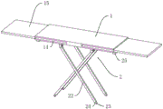
Fig. 1 is a schematic view of the main structure of the present invention;
figure 2 is a bottom view of the table top;
FIG. 3 is an enlarged view at A in FIG. 2;
figure 4 is a side view of the table top with a sleeve;
fig. 5 is an enlarged view at B in fig. 4.
In the figure, 1, a table top board; 11. a turntable; 12. a gear block; 13. a pinch roller; 14. a sub-plate groove; 15. a sub-board; 16. inserting a ring; 17. sleeving a frame; 18. inserting a rod; 19. a toggle rod groove; 2. a lifting device; 21. a slider; 22. a lifting rod; 23. a table leg block; 24. a rubber sleeve; 25. a screw block; 26. a bidirectional screw; 27. a synchronizing gear; 28. an intermediate gear; 29. a synchronous belt; 3. a poke rod; 31. a push spring; 32. a spring slot.
Detailed Description
The present invention will be described in further detail with reference to the accompanying drawings.
Referring to fig. 1, for the utility model discloses an outdoor lift table of high anti-aging of space utilization, including being the cuboid and being horizontally desktop board 1, install the elevating gear 2 that can drive desktop board 1 along vertical direction lift below desktop board 1, in order to prevent ageing, can coat one deck acrylic acid paint on desktop board 1 surface.
Referring to fig. 1 and 2, the lifting device 2 includes two sets of sliding blocks 21 slidably connected to the bottom surface of the table top plate 1 along the length direction of the table top plate 1, the connecting line of the central points of the two sliding blocks 21 in each set is parallel to the length direction of the table top plate 1, the lower surfaces of the four sliding blocks 21 are hinged with lifting rods 22, the central points of the two lifting rods 22 hinged with the two sliding blocks 21 in the same set are hinged, the rotating plane of the two lifting rods 22 hinged with each other is parallel to the length direction of the table top plate 1, the bottom end of the lifting rod 22 is fixedly connected with a hemispherical table foot block 23, the table foot block 23 is sleeved with a rubber sleeve 24, the lower surface of the table top plate 1 is provided with a sliding block driving mechanism capable of driving the two sliding blocks 21 in each set to move in opposite directions, the sliding block driving mechanism includes two screw blocks 25 fixedly connected to the lower surface of the table top plate 1, the, two screw blocks 25 of each group are rotatably connected with two-way screws 26 parallel to the length direction of the table top board 1, each two-way screw 26 is in threaded connection with two sliders 21 of the same group, the thread directions of two sides of the center point of each two screw 26 are opposite, and the distance between the two sliders 21 of the same group and the center point of each two screw 26 is equal, a synchronous rotating mechanism capable of driving the two screw 26 to synchronously rotate is installed on the lower surface of the table top board 1 and comprises two synchronous gears 27 respectively and fixedly connected with one ends of the two screw blocks 26 close to each other, as shown in the combined figure 3, two gear blocks 12 with intervals are fixedly connected with the lower surface of the table top board 1, an intermediate gear 28 with the diameter smaller than that of the synchronous gear 27 is rotatably connected between the gear blocks 12, a pressing wheel 13 close to the intermediate gear 28 is rotatably connected between the two gear blocks 12, and a synchronous belt The upper part of the synchronous belt 29 is arranged between the intermediate gear 28 and the pressing wheel 13 in a penetrating way, the pressing wheel 13 is abutted and tightly meshed with the intermediate gear 28, and the intermediate gear 28 is coaxially and fixedly connected with the rotary table 11.
Referring to fig. 1 and 4, the side of the table top 1 in the thickness direction at both ends in the length direction is provided with an auxiliary plate groove 14, the auxiliary plate groove 14 penetrates through a vertical side of the table top 1 in the length direction, both ends in the length direction of the table top 1 are hinged with auxiliary plates 15 which can be inserted into the auxiliary plate grooves 14, the hinge point of the auxiliary plate 15 and the table top 1 is close to the vertical side of the table top 1 which is not penetrated through by the auxiliary plate grooves 14, the rotation plane of the auxiliary plate 15 is parallel to the upper surface of the table top 1, as shown in fig. 5, when the auxiliary plates 15 are completely unfolded, the vertical side of the auxiliary plate 15 close to the hinge point and parallel to the length direction of the table top 1 is fixedly connected with an insert ring 16, the vertical side of the table top 1 in the length direction which is not penetrated through the auxiliary plate grooves 14 is fixedly connected with a hollow sleeve frame 17, the sleeve 17 is slidably connected with an insert rod 18 which can be inserted into the insert ring 16 along, the vertical side of the inserted link 18 facing the toggle link groove 19 is provided with a spring groove 32 with a T-shaped cross section along the vertical direction, the spring groove 32 is connected with a toggle link 3 which is far away from one end of the inserted link 18 and exposed out of the sleeve frame 17 along the vertical direction in a sliding way, one end of the toggle link 3 exposed out of the sleeve frame 17 is connected with the toggle link groove 19 in a sliding way, a pushing spring 31 with two ends respectively abutted against the inner wall of the upper part of the spring groove 32 and the upper surface of the part of the toggle link 3 positioned in the spring groove 32 is installed in the spring groove 32, when the subplate 15 is completely unfolded, the inserted link 18 is inserted into the insert ring 16 by moving the toggle link 3, at the moment, the toggle link 3 corresponds to the vertical section of the toggle link groove 19, and then under the action of the pushing spring 31, the toggle link 3 is abutted against the bottom surface of the vertical section of.
The implementation principle of the embodiment is as follows: the two bidirectional screws 26 can rotate synchronously by rotating the turntable 11, and then the two sets of two sliders 21 are close to each other, so that the table top plate 1 is lifted up until the turntable 11 stops rotating at a proper height.
The embodiment of this specific implementation mode is the preferred embodiment of the present invention, not limit according to this the utility model discloses a protection scope, so: all equivalent changes made according to the structure, shape and principle of the utility model are covered within the protection scope of the utility model.
Claims (8)
1. The utility model provides a high anti-aging outdoor lifting table is utilized in space, includes desktop board (1), locates desktop board (1) below and plays elevating gear (2) of elevating system to desktop board (1), its characterized in that: the lifting device (2) comprises two groups of two sliding blocks (21) which are connected with the bottom surface of the desktop plate (1) in a sliding manner along the length direction of the desktop plate (1), two groups of two lifting rods (22) which are respectively hinged with the two sliding blocks (21) of the same group, and a sliding block driving mechanism which is arranged on the bottom surface of the desktop plate (1) and drives the sliding blocks (21) to slide along the length direction of the desktop plate (1), wherein the rotating planes of the two lifting rods (22) which are hinged with the central points of the same group are parallel to the length direction of the desktop plate (1).
2. The outdoor elevating table with high space utilization for aging prevention as claimed in claim 1, wherein: the bottom end of the lifting rod (22) is fixedly connected with a table leg block (23) which is a hemisphere, and the table leg block (23) is provided with a rubber sleeve (24).
3. The outdoor elevating table with high space utilization for aging prevention as claimed in claim 2, wherein: the slider drive mechanism includes two sets of and two screw blocks (25) of every group of fixed connection in desktop board (1) lower surface, two and every rotate respectively connect in with between two screw blocks (25) of a set of and threaded connection in two-way screw (26) of two sliders (21) of a set of, locate desktop board (1) lower surface and drive two-way screw (26) synchronous pivoted synchronous slewing mechanism, the opposite and same two sliders (21) of group of screw direction of two-way screw (26) central point apart from two-way screw (26) central point distance equals.
4. The outdoor elevating table with high space utilization and aging resistance as claimed in claim 3, wherein: the synchronous rotating mechanism comprises two synchronous gears (27) which are respectively and coaxially and fixedly connected with the two bidirectional screw rods (26), two gear blocks (12) fixedly connected below the table top plate, an intermediate gear (28) rotatably connected between the two gear blocks (12), a synchronous belt (29) in transmission connection with the intermediate gear (28) and the two synchronous gears (27), and a rotary disc (11) coaxially and fixedly connected with the intermediate gear (28).
5. The outdoor elevating table with high space utilization and aging resistance as claimed in claim 4, wherein: the diameter of the intermediate gear (28) is smaller than that of the synchronous gear (27), and the pressing wheel (13) which is attached to the outer wall of the synchronous belt (29) and enables the synchronous belt (29) to be tightly attached to the intermediate gear (28) is rotatably connected between the two gear blocks (12).
6. The outdoor elevating table with high space utilization for aging prevention as claimed in claim 5, wherein: auxiliary plate grooves (14) are formed in the thickness vertical side walls at the two ends of the length direction of the desktop plate (1), and auxiliary plates (15) which can be respectively inserted into the two auxiliary plate grooves (14) are hinged to the two ends of the length direction of the desktop plate (1).
7. The outdoor elevating table with high space utilization for aging prevention as claimed in claim 6, wherein: the auxiliary plate (15) is close to a vertical side fixedly connected with an inserting ring (16) which is hinged with the desktop plate (1) and is flush with the vertical side wall of the desktop plate (1) in the length direction, the desktop plate (1) is close to a vertical side fixedly connected with a sleeve frame (17) at the hinged point of the auxiliary plate (15), and the sleeve frame (17) is connected with an inserting rod (18) which can be inserted into the inserting ring (16) in a sliding mode along the length direction of the sleeve frame (17).
8. The outdoor elevating table with high space utilization for aging prevention as claimed in claim 7, wherein: the outer wall that the jacket frame (17) deviates from desktop board (1) runs through and sets up toggle rod groove (19) that are L shape, and inserted bar (18) have poking rod (3) along vertical direction sliding connection, and poking rod (3) sliding connection is in toggle rod groove (19), and inserted bar (18) inside is equipped with both ends respectively butt in poking rod (3) and inserted bar (18) inside promotion spring (31).
Priority Applications (1)
| Application Number | Priority Date | Filing Date | Title |
|---|---|---|---|
| CN202020867654.5U CN212815015U (en) | 2020-05-21 | 2020-05-21 | Anti-aging outdoor lifting table with high space utilization |
Applications Claiming Priority (1)
| Application Number | Priority Date | Filing Date | Title |
|---|---|---|---|
| CN202020867654.5U CN212815015U (en) | 2020-05-21 | 2020-05-21 | Anti-aging outdoor lifting table with high space utilization |
Publications (1)
| Publication Number | Publication Date |
|---|---|
| CN212815015U true CN212815015U (en) | 2021-03-30 |
Family
ID=75168995
Family Applications (1)
| Application Number | Title | Priority Date | Filing Date |
|---|---|---|---|
| CN202020867654.5U Active CN212815015U (en) | 2020-05-21 | 2020-05-21 | Anti-aging outdoor lifting table with high space utilization |
Country Status (1)
| Country | Link |
|---|---|
| CN (1) | CN212815015U (en) |
Cited By (1)
| Publication number | Priority date | Publication date | Assignee | Title |
|---|---|---|---|---|
| CN117223973A (en) * | 2023-09-14 | 2023-12-15 | 中国十七冶集团有限公司 | A prefabricated building design platform based on BIM technology and its use method |
-
2020
- 2020-05-21 CN CN202020867654.5U patent/CN212815015U/en active Active
Cited By (1)
| Publication number | Priority date | Publication date | Assignee | Title |
|---|---|---|---|---|
| CN117223973A (en) * | 2023-09-14 | 2023-12-15 | 中国十七冶集团有限公司 | A prefabricated building design platform based on BIM technology and its use method |
Similar Documents
| Publication | Publication Date | Title |
|---|---|---|
| CN209284520U (en) | Dining table with adjustable tabletop area | |
| CN214963629U (en) | Anticorrosion bookshelf for books | |
| CN110720749B (en) | Fixed pulley type liftable drawing table | |
| CN204797051U (en) | Hand formula lift table | |
| CN207179419U (en) | A kind of light trough structure of ceiling | |
| CN212574559U (en) | Single-motor linked lifting mattress | |
| CN201518896U (en) | Automatic lifting table | |
| CN217806692U (en) | Storage rack lifting device | |
| CN220141259U (en) | Agricultural product sales exhibition stand | |
| CN219229269U (en) | Full-folding installation-free electric lifting table | |
| CN214377174U (en) | A reminder device for Vietnamese oral practice | |
| CN210144135U (en) | Diameter-variable folding dining table with folding device | |
| CN214227531U (en) | Portable power distribution cabinet | |
| CN211315654U (en) | High-efficient display device beneficial to computer teaching | |
| CN216316263U (en) | Disk linkage elevation structure and desk in middle of desk | |
| CN211647969U (en) | Communication is maintained and is maintained with multi-functional lifting device that maintains | |
| CN223169352U (en) | Electric dining table capable of changing size and size | |
| CN114305014B (en) | Combined display equipment for cultural creative products | |
| CN218032141U (en) | Movable teaching frame | |
| CN113775877A (en) | Multimedia teaching system for art design and method thereof | |
| CN116530770B (en) | A stretchable folding table | |
| CN216711499U (en) | Maintenance support frame for auto repair | |
| CN217851789U (en) | Simple foldable table with legs convenient to stretch | |
| CN219877681U (en) | Movable platform | |
| CN215769931U (en) | Self-service equipment for electric power marketing |
Legal Events
| Date | Code | Title | Description |
|---|---|---|---|
| GR01 | Patent grant | ||
| GR01 | Patent grant |